C ATM Signaling Link Configuration

Appendix C, ATM Signaling Link Configuration, contains general information about the ATM high-speed signaling links and how to provision them.

C.1 Introduction

ATM (Asynchronous Transfer Mode) is a transport mechanism that uses virtual connections for transporting information across the network. The ATM layer uses the VPI and VCI fields to define multiple Virtual Channel Connections (VCC). Within each VCC, the PTI field is used to distinguish one type of traffic from another. A true ATM switch can support multiple VPI/VCI combinations. The EAGLE supports only a single VPI/VCI combination.

ATM is a specific packet-oriented transfer mode that uses an asynchronous time division multiplexing technique to multiplex information flow in fixed blocks, called cells. ATM replaces MTP-1 (Signaling Data Link Functions) and MTP-2 (Signaling Link Functions) in the SS7 protocol stack.

Signaling data link functions (MTP-1) are provided by an appropriate physical layer in combination with the ATM layer, signaling link functions (MTP-2) are provided by the Signaling ATM Adaptation Layer (SAAL), and the signaling network functions are provided by MTP level 3. Figure C-1 illustrates the high-speed link protocol model for CCS NEs.

Figure C-1 High-Speed Link Protocol Model for CCS Network Elements

img/c_introduction_atm_slk_config_dbadmin_ss7-fig1.jpg

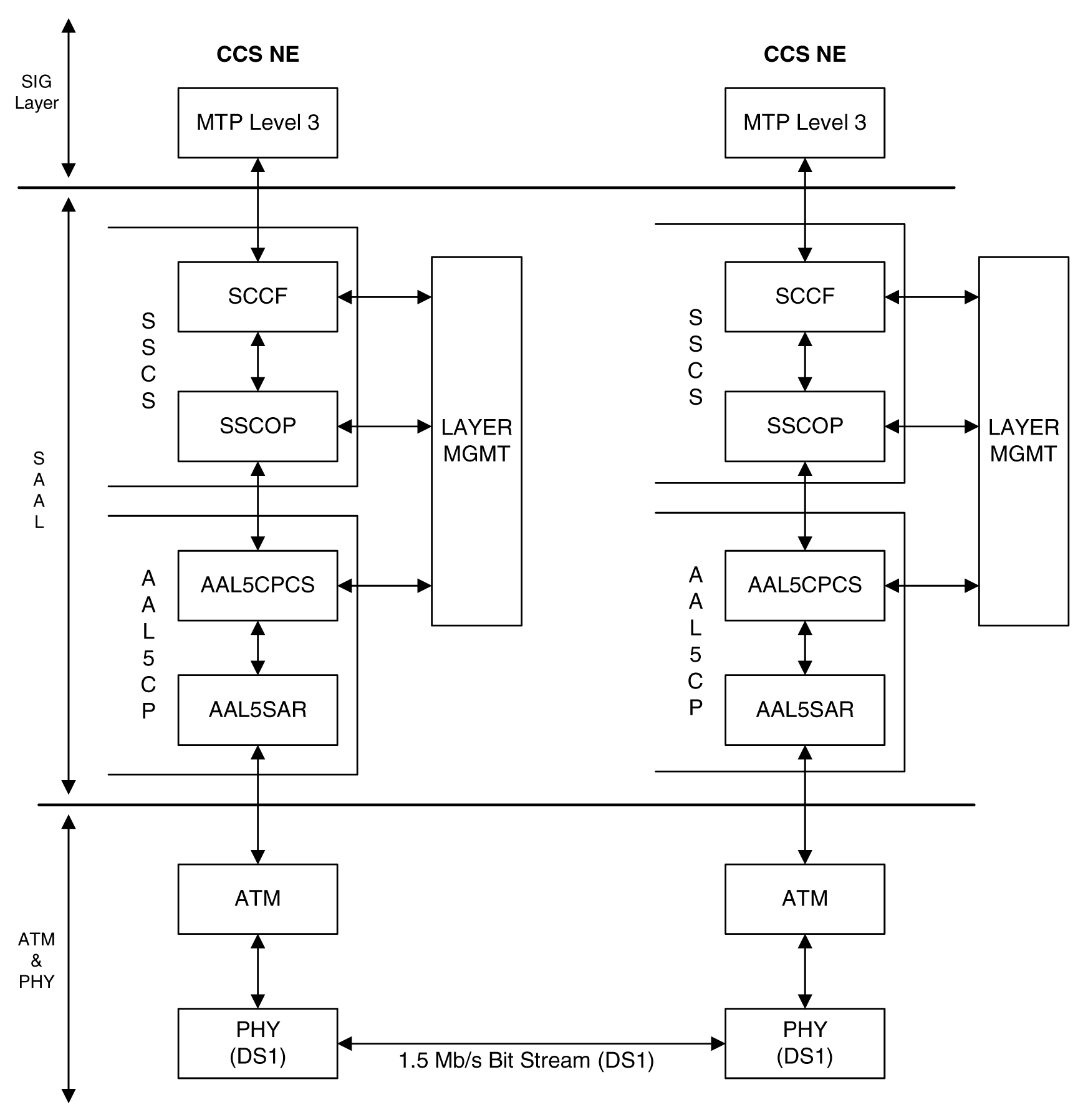
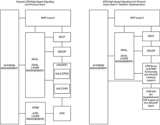
Figure C-2 illustrates some slight differences between the SAAL and ATM layers and the actual protocol stack used in the Oracle implementation. These differences are as a result of 3 reasons:

  • The AATM hardware provides AAL5CP protocol support (primarily segmentation and reassembly of User Data PDUs), thus providing the AAL5CP functionality in hardware not software. The AATM hardware also provides CRC10 support for OAM F5 ATM cell flows.

  • The ATM driver is not a defined block in the protocol model, but is needed in the Oracle implementation to control and interface with the AATM hardware. The ATM driver provides the software interface to the hardware AAL5CP functionality. The ATM driver also provides the ATMM (ATM Layer Management) functions that are supported in the EAGLE.

  • As a part of providing ATM (MTP-level 2 equivalent) functionality into the existing EAGLE software (based on MTP-3 and MTP- 2, not MTP-3 and SAAL), some of the interfaces to and from MTP level 3 will be to and from MAAL (rather than SSCF handling all MTP-3 interaction).

The EAGLE implements an ANSI ATM high-speed signaling link, transmitting at a rate of 1.544 Mbps, and an E1 ATM high-speed signaling link, transmitting at a rate of 2.048 Mbps. Most of the ANSI and E1 ATM implementations are the same, but there are a few differences. The descriptions in this appendix apply to both implementations. Any differences between ANSI and E1 ATM are noted.

Figure C-2 ATM High-Speed Signaling Link Protocol Stack vs. Oracle Implementation in the EAGLE

img/tekelec_atm_hsl_protocol_stack.jpg

Another way of viewing the high-speed signaling link implementation is to consider the frame formats of the data that is relevant at the various protocol stack layers. Figure C-3 illustrates the differences between the frame formats for high-speed signaling link layers versus the frame formats for traditional (MTP-2 & MTP-1) low-speed signaling link layers.

Figure C-3 Frame Formats for High-Speed and Low-Speed Signaling Link Protocol Stacks

img/hsl-lsl_protocol_stacks.jpg

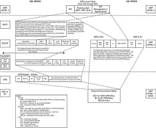
Based on Figure C-3, the following conclusions can be made regarding the ATM traffic and how ATM is used to carry MTP3 data:

  • The ATM layer uses the VPI and VCI fields to define multiple Virtual Channel Connections (VCC). Within each VCC, the PTI field is used to distinguish 1 type of traffic from another. A true ATM switch can support multiple VPI/VCI combinations. The EAGLE high-speed signaling link implementation needs to support only a single VPI/VCI combination.

  • The ATM stack contains built in fields that are used to check the integrity of the data that is received across the T1 connection. The ATM cell HEC field and the AAL5CP CRC-32 fields are used for data integrity.

  • MTP3 data (or MSUs) is transferred as User Data at the ATM cell level. A single MSU will require 1 or more ATM cells to transfer that MSU.

  • A significant amount of ATM protocol overhead is involved in transferring MSUs. The overhead includes:

    • ATM cell headers

    • AAL5CP layer pad bytes and trailer

    • SSCOP layer pad bytes and trailer

  • In addition to transferring MSUs, the ATM stack is capable of transferring

    • SSCOP Peer to Peer Messages - these are used primarily for connection setup and tear down and the acknowledgment of transferred data

    • SSCF Peer to Peer Messages - these are used primarily for high-speed signaling link alignment and proving

ATM Protocol Encapsulation

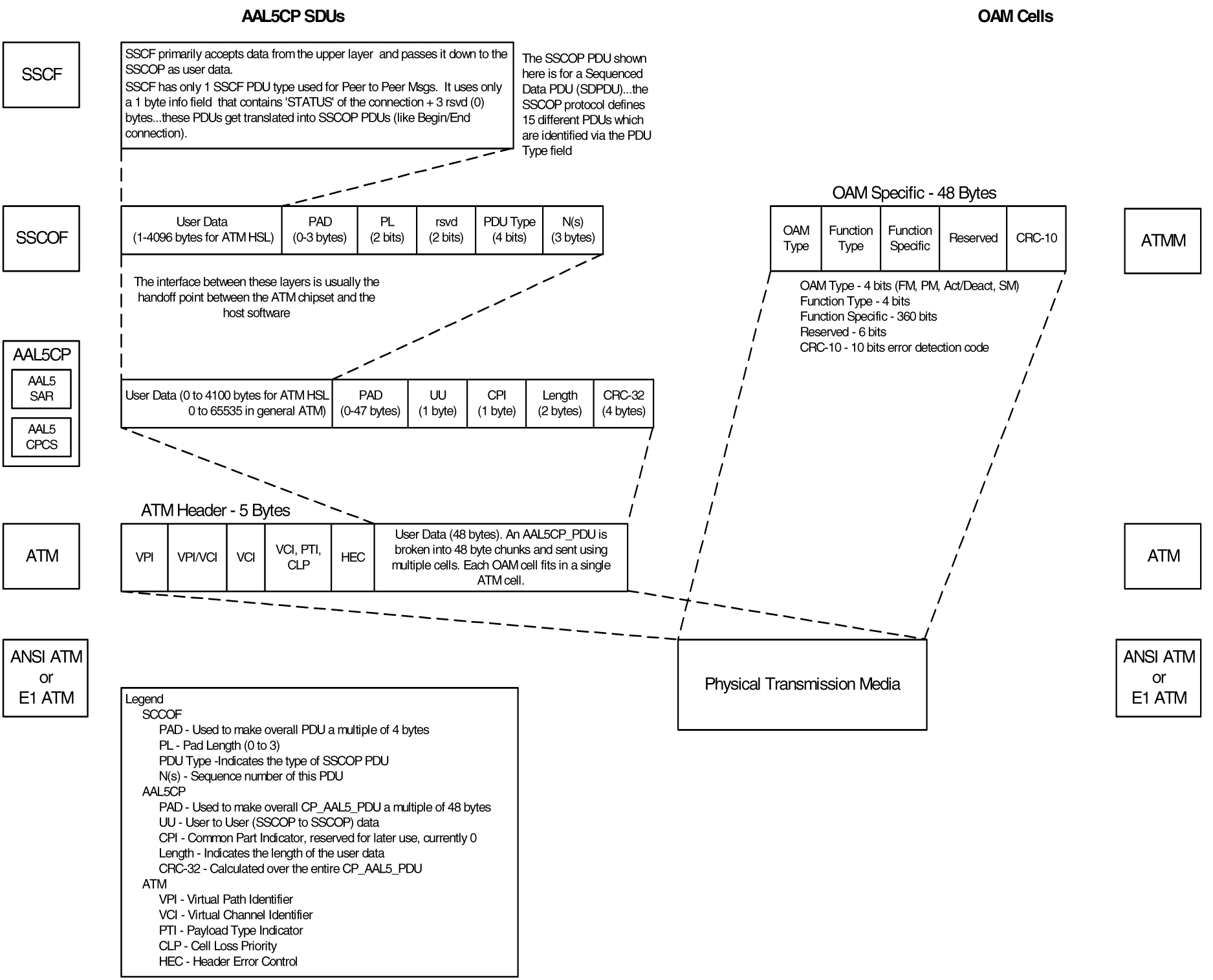
Two main types of data are delivered using ATM: SDUs and OAM cells. SDUs provide peer-to-peer information and user data (MSUs). OAM cells are used for operations and maintenance of the ATM connection. Figure C-4 provides the data encapsulation through the ATM stack. MTP3 is a user of SSCF and passes all PDUs directly to it.

Figure C-4 ATM Protocol Encapsulation

img/c_introduction_atm_slk_config_dbadmin_ss7-fig4.jpg

Payload Scrambling

Payload scrambling uses the x43+1 scrambling function.

Idle Cells

Idle cells uses the following 5-byte header format:

0x00 0x00 0x00 0x01 0x52.

The content of the information field shall be 0x6A repeated 48 times.

Since idle cells are transmitted on VPI=0, VCI=0, they are immediately discarded by the receiving end.

C.2 Overview of the ATM High-Speed Signaling Link LIM Operation

To other cards in the EAGLE , the ANSI ATM and E1 ATM high-speed signaling link cards look and operate similar to any other LIMs (with the exception of subtle differences related to load balancing for SCCP traffic), but has the potential for increased data throughput with respect to traditional EAGLE LIMs.

The ANSI and E1 ATM high-speed signaling link cards can perform gateway screening, copy and redirect, conversion and any of the other EAGLE features that any other LIM can perform (with the exception of link fault sectionalization).

A functional block diagram of the ATM high-speed signaling link is shown in Figure C-5.

Figure C-5 Functional Block Diagram of ATM High-Speed Signaling Link

img/c_overview_atm_high_speed_slk_lim_operation_atm_slk_config_dbadmin_ss7-fig1.jpg

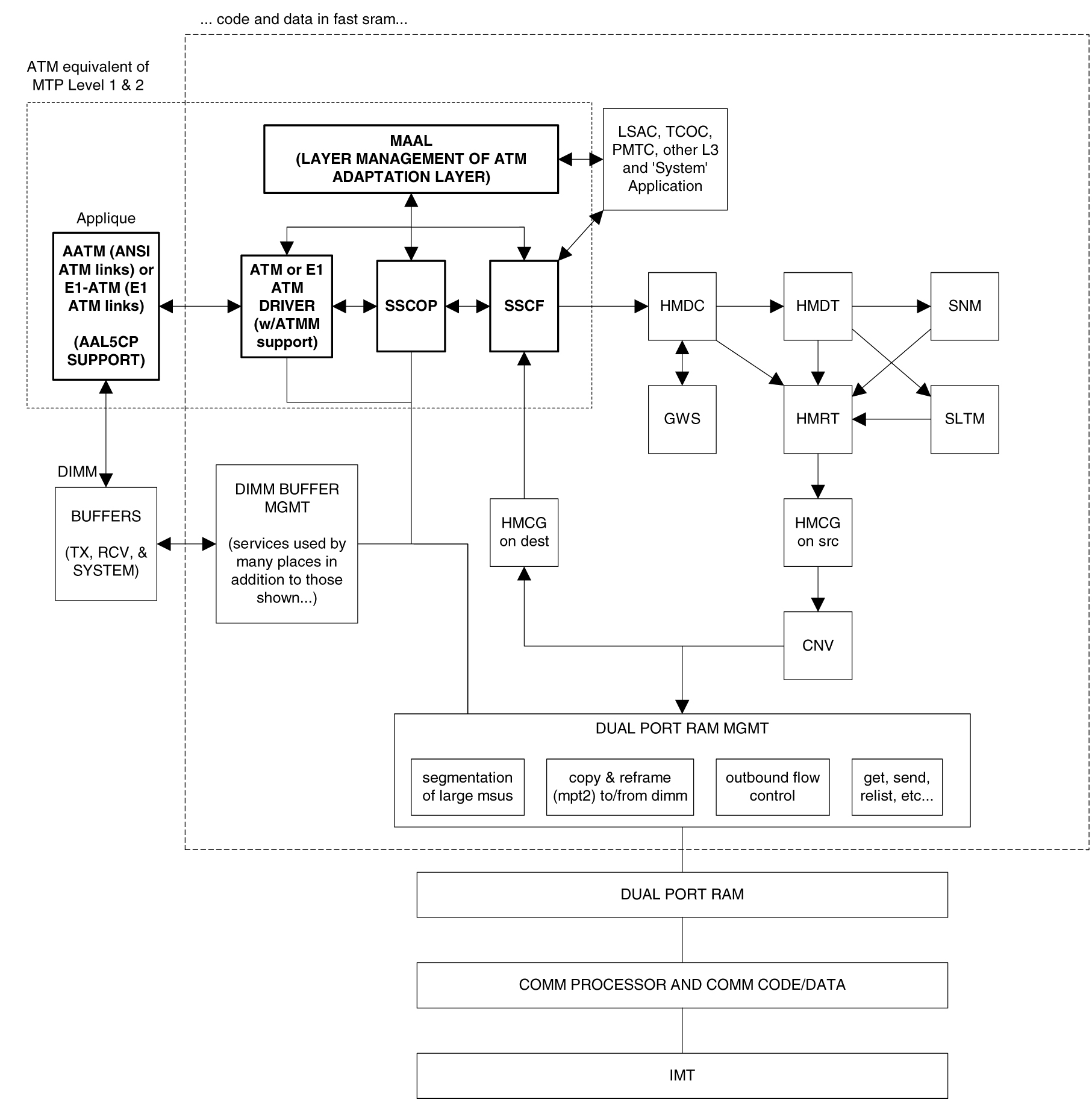
The following sections provide more details for each of the new applications/processes (indicated by the bold boxes in Figure C-5) required for the ATM high-speed signaling link implementation. These sections will include information such as:

  • the specification(s) that defines the layer
  • highlights of the functionality provided by the application/process (what problems are being solved here)
  • any limitations/restrictions from specifications that apply to the EAGLE implementation
  • other information as appropriate

Applique

ANSI ATM

The ANSI ATM hardware consists of an AATM applique connected to an HCAP or HCAP-T main assembly. The AATM hardware provides the following functionality:

  • support for the DS1, ATM, and AAL5CP layers of the ATM high-speed signaling link protocol stack as indicated in Figure C-1.
  • DS1 Layer support
    • generate DS1 signals

    • support for DS1 defect reporting:

      • LOS
      • LOF
      • LCD
      • In-band AIS signals
    • support for loopback testing at the DS1 level
    • support for DS1 performance measurements and performance monitoring
  • ATM Layer support

    • idle cell insertion/removal
    • provide adequate indications of ATM layer errors:
      • invalid ATM header patterns
      • unsupported VPI/VCI combinations
      • unsupported PTI values
      • cells discarded due to header error control
      • out of cell delineation anomalies
    • header error control field to be automatically inserted/checked by the hardware
    • CLP field of cells received is made available to software
    • ability to DMA received cells directly to DIMM receive buffers
    • ability to DMA cells to transmit directly from DIMM transmit buffers
    • needs to support interleaved transmit/reception of data from different VPI/VCI combinations, or from OAM F5 flows as opposed to user data flows, these need to each be passed to higher layers using different queues or data structures
    • congestion indications for cells are made available to software; software can set the congestion indications for outbound traffic.
  • OAM F5 cell support
    • only end to End OAM F5 cells for a VCC need to be supported
    • shall support generation (outbound) and processing (inbound) of OAM cell types for VCC F5 flows
    • shall indicate reception of these cells in a distinct manner from user data cells
    • provide CRC-10 checking/generation for these frames
  • AAL5CP Layer support

    • perform the segmentation/reassembly required for user data cells and ability to pass user data to/from the SSCOP in an efficient manner (whether this is via some linked list of ATM cells that together make up 1 AAL5CP_PDU, or via regrouping ATM cells as they arrive into 1 continuous AAL5CP_PDU is implementation dependent).
    • provide CRC-32 generation/checking for AAL5CP_PDUs
    • should stuff outbound AAL5CP_PDUs with 0 in the CPI field
    • appropriate error checking and indications for errors
      • CRC errors
      • Length errors
      • CPI errors
    • some fields of the AAL5CP_PDU need to be passed to/from the higher layers
      • UU
      • CLP
      • Congestion indication

E1 ATM

The E1 ATM hardware consists of an E1 ATM applique connected to an HCAP or HCAP-T main assembly. The E1 ATM hardware performs the same functions as the ANSI ATM hardware, with these exceptions:

  • support for the E1, ATM, and AAL5CP layers of the ATM high-speed signaling link protocol stack as indicated in Figure C-5.
  • E1 layer support
    • Support CRC-4
    • Support Si and Sn insertion in Channel 0
    • Support E1 defect reporting:
      • LOS
      • LOF
      • LCD
  • OAM F5 cell support - only end-to-end OAM F5 cells for a VCC are required to be supported

E1 Overview

This section provides an overview of E1, its protocol and characteristics.

Frame Structure

E1 is a 2.048 Mbps interface. It has a frame structure of 256 bits that is repeated at a rate of 8 KHz. The 256-bit frame is broken into 32 eight-bit time timeslots, numbered 0 to 31, as shown in Figure C-6. Timeslots can also be referred to as channels.

Figure C-6 E1 Frame Structure
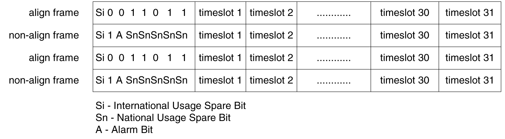
img/c_overview_atm_high_speed_slk_lim_operation_atm_slk_config_dbadmin_ss7-fig2.jpg

Timeslot 0

Timeslot 0 is used for frame alignment and CRC functions. Alternating frames contain the Frame Alignment Signal (FAS), X0011011, where X is supplied from the International Usage Spare Bit information (Si). Frames without the FAS carry Si, Alarm, and Sn information. Bit 1 is set to 1 to prevent accidental emulation of the FAS.

Si is reserved for international usage. CRC-4 specified below is one specific use. If no use is specified, Si should be set to 1. Sn is a 5-bit field (value 0 – 31). ‘A’ is an alarm bit. If set, it indicates a remote alarm indication.
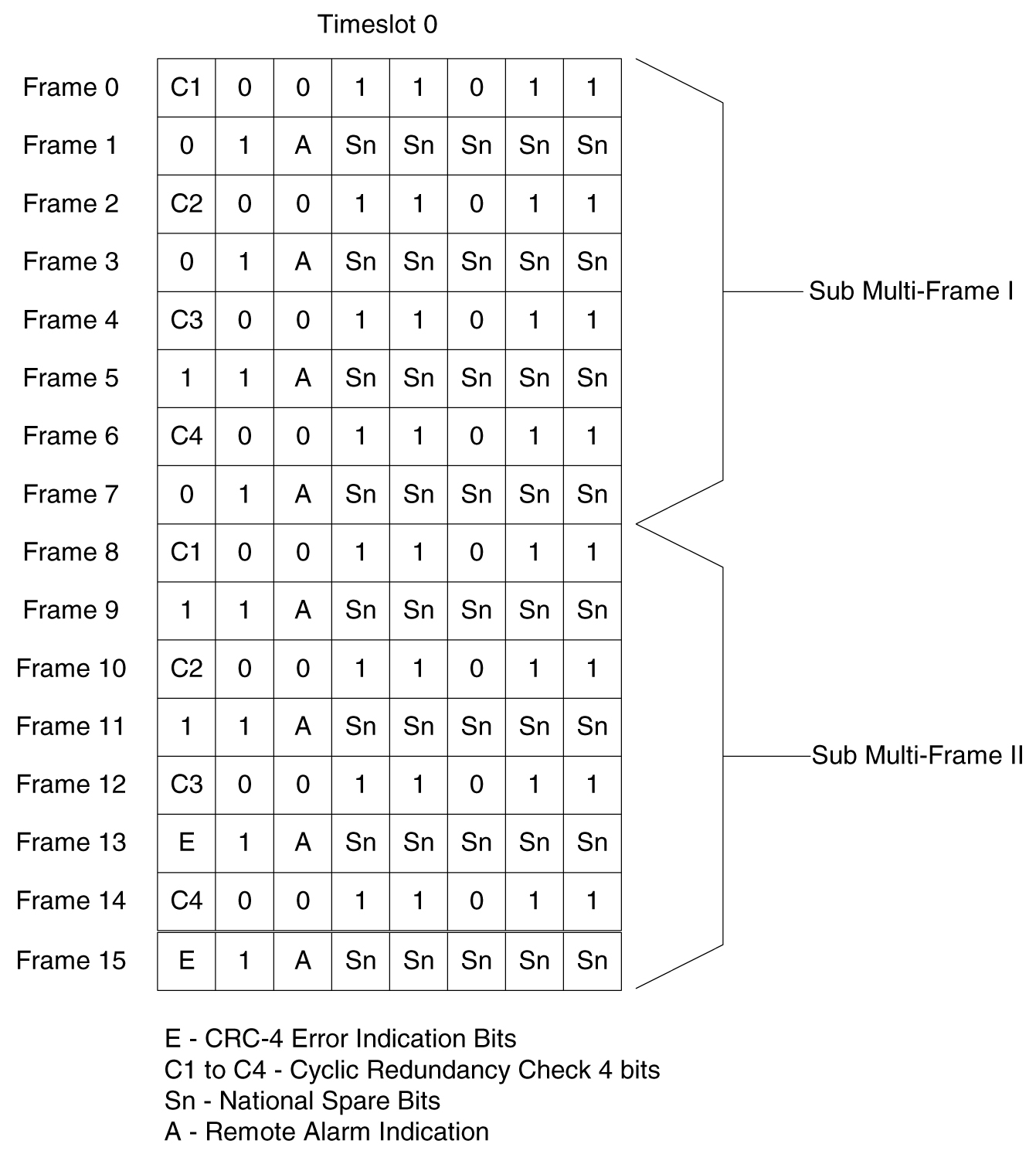
CRC-4

A CRC-4 multi-frame structure is shown in Figure C-7. CRC-4 uses timeslot 0 primarily to aid in frame alignment validation but can be used to monitor error performance as well. A CRC multi-frame consists of timeslot 0 information from 16 consecutive frames. Each CRC-4 multi-frame is divided into 2 eight-frame sub-multi-frames (SMF).

Bit 1 is used to carry 3 different pieces of information:

  • A multi-frame alignment word is a repeating 6-bit code (001011) that is located in frames 1,3,5,7,9, and 11.
  • A 4-bit CRC code word (C1, C2, C3, C4), which is a data check on the previous 8 E1 frames. The check covers the data for all 32 timeslots. (8 frames * 256 bits/frame = 2048 bits) Each SMF has its own code word. The code word for SMF I is in frames 0, 2, 4 and 6. The code word for SMF II is in frames 8, 10, 12, and 14.
  • E (CRC-4 Error indication) bits, present in frames 13 and 15.

The Alarm Indication Signal is received in Channel 0, Bit 3 of the non-alignment frame. If this bit is set, it indicates a Remote Alarm Indication. As with the ANSI ATM, this condition is ignored.

Bits 2 through 8 follow the standard E1 frame structure.

If CRC-4 in on, the provisioned Si information is not used. Instead, bit 0 is used for CRC4 information, CRC4 error reporting, and for multiframe alignment (see Figure C-7).

Figure C-7 CRC-4 Multiframe Structure
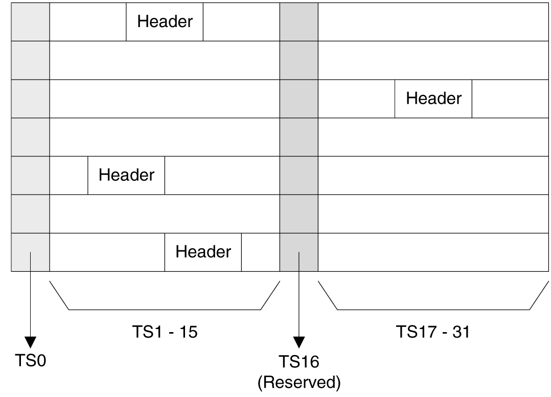
img/c_overview_atm_high_speed_slk_lim_operation_atm_slk_config_dbadmin_ss7-fig3.jpg

ATM Mapping into E1

Data channels 1 – 15 and 17 - 31 carries the data for a single ATM channel, as shown in Figure C-8. Note that the ATM cell size does not map directly over the E1 frame format, so the ATM cell can start in any data channel. The data is octet-aligned.

Figure C-8 ATM Cell Mapping into E1 Frames

img/c_overview_atm_high_speed_slk_lim_operation_atm_slk_config_dbadmin_ss7-fig4.jpg

ATM Driver

The ATM driver is a software module, residing as part of the ATMANSI or ATMITU applications, that provides the code required to interface between the AATM hardware and the SSCOP layer and ATM Layer Management interfaces. The primary functions of the driver include:

  • initialization and control of the AATM hardware
  • interface between AATM hardware signals and data structures and the relevant messages/data to/from the SSCOP and ATM Layer Management layers
  • provide the DIMM buffer management interface required for the AATM hardware for user data received and transmitted (that is, provide free receive buffer lists for the AATM hardware after grabbing buffers from DIMM mgmt, provide information detailing where to transmit user data from, etc.)
  • some of the functions listed above in the AATM hardware section (such as providing separate ‘receive channels’ for OAM F5 vs. user data cells to/from higher levels) may actually be performed in this layer based on the actual ATM hardware solution selected
  • the only type of AAL service needed is for AAL Type 5 (AAL5)
  • the AATM hardware and ATM driver together make up the common part of the SAAL layer, also known as the Common Part Convergence Sublayer (CPCS) or AAL5CP, when the AAL type in question is AAL5.

E1 ATM Driver

The E1 ATM driver is a software module that provides the interface between the E1 ATM hardware, the SSCOP layer, and ATM Layer Management Module. The E1 ATM driver exists only in the ATMITU application. The basic structure is based upon the ANSI ATM driver present in the ATMANSI application. The primary changes to the existing ANSI ATM driver include:

  • initialization and control of the new E1 ATM appliqué.
  • remove T1 support of 4 Kbps data link (BOCs, including performance reports and T1 loopback tests)
  • verify correct E1 ATM appliqué is installed and reboot if not

SSCOP

The primary task of the SSCOP (Service Specific Connection Oriented Protocol) is to provide assured data delivery between AAL connection endpoints. The SSCOP is 1 of 2 parts (the other being the SSCF) of the Service Specific part of the SAAL layer (also known as the SSCS, the Service Specific Convergence Sublayer of the SAAL). The other part of the SAAL Layer is the CPCS (which was just mentioned in the ATM driver). Breaking the SSCS into 2 sublayers allows a common connection oriented protocol with error recovery (the SSCOP) to provide a generic reliable data transfer service for different AAL interfaces defined by different SSCF layers. The primary functions of the SSCOP layer include:

  • transfer of user data with sequence integrity
  • error correction by selective retransmission
  • flow control
  • connection control
  • error reporting to layer management
  • connection maintenance in the prolonged absence of data transfer
  • local data retrieval by the user of the SSCOP
  • error detection of protocol control information
  • status reporting

SSCF

The primary task of the SSCF (Service Specific Coordination Function) is to map the services provided by the lower layers of the SAAL to the needs of a specific higher layer user. For the ATM high-speed signaling link, the higher layer user is the MTP-3 protocol.

  • maps signals/primitives from MTP-3 (SSCF user) to SSCOP, and vice versa.
  • performs local retrieve function, required by the changeover order.
  • flow control on transmit direction (SSCF notifies the user of congestion levels)
  • maintains and controls the link status
  • generates necessary reports to ATM Layer Management (primarily the cause for the release of the SSCOP connection)
  • implements some SSCF to SSCF, peer to peer messages primarily related to connection establishment and release
  • controls local and remote processor outage and recovery
  • controls the alignment procedure

For an E1 ATM high-speed signaling link, the link proving default values are significantly different compared to an ANSI ATM high-speed signaling link. Table C-1 illustrates the different link proving values.

Table C-1 Link Proving Differences Between ITU and ANSI

CHG-ATM-LPS Parameter Name

Description

E1 ATM Default Values

ANSI ATM Default Values

N1

Number of PDUs sent during link proving

1000

64552

TmrT2

Time to attempt link proving

30 sec

120 sec

maxnrp

Maximum number of retransmitted PDUs during proving

0

1

TmrT3

Time between proving PDUs

925 sec

925 sec

The time required for normal ANSI proving is approximately 60 seconds (925 sec/pdu * 64552 PDUs = 60 seconds). This time is greater than TmrT2 value for an E1 ATM high-speed signaling link (30 seconds), so a link with E1 ATM defaults would have gone out of service before a link with ANSI ATM defaults finishes proving. Thus, great care must be taken to ensure that compatible proving numbers are assigned to a signaling link.

ATM and SAAL Layer Management Interfaces

The primary task of the ATM and SAAL layer management layers is to map requests and indications between the system management for the EAGLE and the individual ATM, AAL5CP, SSCOP, and SSCF layers. This functionality is actually achieved using two management modules, which both interface to the system management.

ATM Layer Management

ATM layer management is achieved with the ATMM (ATM layer management module). The ATMM provides a supporting role for system management functions which include fault, performance, configuration, security and resource management functions. It is the job of the system management to coordinate with different layers locally to perform all tasks associated with these functions. The ATMM entity uses two types of interactions with the ATM entity to perform its functions. The first type of interaction is for the exchange of info between the ATM and ATMM entity. The second type of interaction is for peer to peer communication between ATMM entities (between the two nodes on both ends of the high-speed signaling link). This second interaction is achieved by sending and receiving and processing OAM F5 cells in the ATM high-speed signaling link implementation. The primary functions provided by the ATMM for an ANSI ATM high-speed signaling link include:

  • OAM F5 fault management: includes alarm surveillance, loopback using OAM cells, and continuity check
  • OAM F5 performance management: includes activation and deactivation of performance monitoring, forward and backward monitoring and reporting of performance to system management.

    Note:

    The general ATMM layer is capable of performing performance management functionality. The ATMM layer implemented by ATM high-speed signaling link does not support this capability.

The primary functions provided by the ATMM for an E1 ATM high-speed signaling link include only OAM F5 fault management: loopback by OAM cells. All other forms of OAM F5 management and OAM F5 performance management are not supported.

SAAL Layer Management

The SAAL layer management includes interfaces to and from AAL5CP, SSCOP, SSCF, and system management. SAAL layer management supports the following functions:

  • error processing for these layers
  • error monitoring for in-service links
  • detection of excessive time with no credit
  • detection of closely spaced SSCOP recoveries
  • measurements
  • duration of presence in the in-service state
  • signaling link failures
  • signaling link restoration
  • handling of processor outage conditions
  • management of signaling link proving

C.3 ATM High-Speed Signaling Link Testing Capability

Local Loopback Support

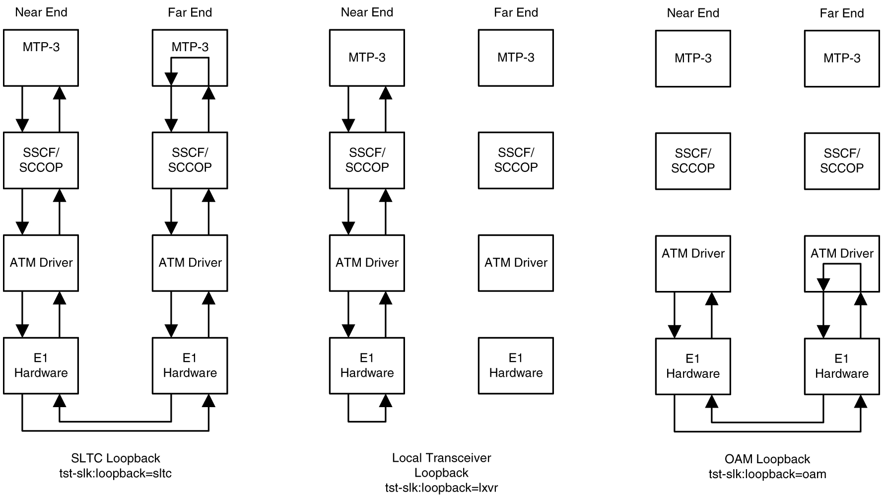
There are five link testing capabilities for an ATM high-speed signaling link. All five of these tests can be used for an ANSI ATM high-speed signaling link; three of these tests can be used for an E1 ATM high-speed signaling link. Table C-2 gives a description of each test and shows which the type of ATM high-speed signaling link each test can be used. Figure C-9 and Figure C-10 show diagrams of each test.

Table C-2 ATM High-Speed Signaling Link Loopback Support

Loopback Type ANSI ATM High-Speed Signaling Link E1 High-Speed High-Speed Signaling Link When can the Loopback Test be Performed How does the Loopback test Work What is Tested (Assume Near End Unless Specified)

SLTC

Yes

Yes

When the link is in service and activated

MTP-3 exchanges SLTM/SLTA messages with remote MTP-3. Appears as normal MSU traffic to SSCF and SSCOP.

MTP-3 layer, ATM protocol stack (near end and far end), and wire

OAM

Yes

Yes

When the link is connected to a remote STP. The state of the link is either activated or deactivated.

ATM driver exchanges OAM F5 Loopback cells with remote ATM driver. One OAM cell per request with a maximum of three attempts made.

ATM driver (near end and far end) and wire

LXVR

Yes

Yes

When the link is deactivated.

MTP-3 attempts to align link. If alignment fails, test fails. Appears as normal alignment request to SSCF and SSCOP.

SSCF, SSCOP, ATM driver and T1 hardware (for an ANSI ATM high-speed link) or E1 hardware (for an E1 ATM high-speed signaling link) on near end

Payload

Yes

No

When the link is deactivated, connected to remote STP and no Yellow Alarm BOC is being transmitted.

MTP-3 attempts to align link. If alignment fails, test fails. Appears as normal alignment request to SSCF and SSCOP.

SSCF, SSCOP, ATM driver (near end only) and T1 hardware (near end and far end) and wire

Line

Yes

No

When the link is deactivated and connected to remote STP and no Yellow Alarm BOC is being transmitted.

MTP-3 attempts to align link. If alignment fails, test fails. Appears as normal alignment request to SSCF and SSCOP.

SSCF, SSCOP, ATM driver (near end only) and T1 hardware (near end and far end) and wire

Figure C-9 ANSI ATM High-Speed Signaling Link Loopback Support

img/c_atm_high_speed_slk_test_capability_atm_slk_config_dbadmin_ss7-fig1.jpg

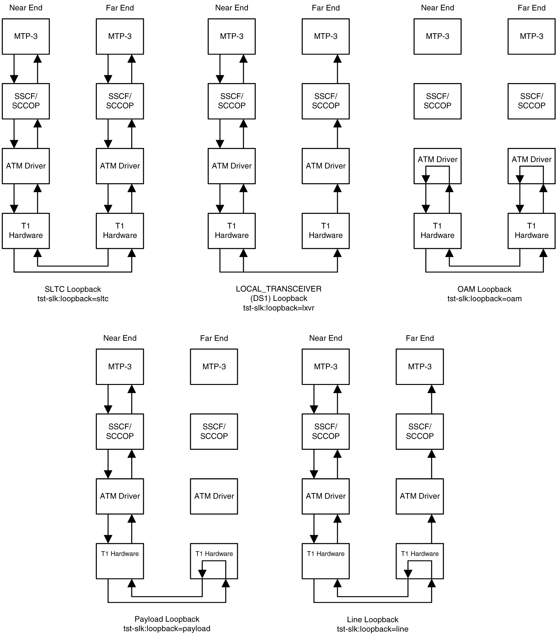
Figure C-10 E1 ATM High-Speed Signaling Link Loopback Support

img/c_atm_high_speed_slk_test_capability_atm_slk_config_dbadmin_ss7-fig2.jpg

Remote Loopback Support

The LIM containing the ATM high-speed signaling link must provide remote loopback support so that the EAGLE 5 ISS can act as the far end STP as shown in Figure C-9 or Figure C-10. The support provided for ATM high-speed signaling link cards is identical to low-speed signaling link cards by providing the same initialization and detection capabilities.

  • initialization - The MTP-3 layer, independent of hardware interface, allows remote loopbacks when the link is deactivated. Upon receiving a bit-oriented code for a line or payload loopback, the ATM high-speed signaling link reprograms the AATM hardware if MTP-3 has determined a remote loopback is allowed.
  • detection - Every 500 ms, the hardware is read to determine if remote loopback is in progress and the maintenance block is updated. This generates a UAM to the local node. For DS1 links, an AATM hardware register is read to determine if the T1 layer is currently configured for remote loopback.

Link Status Logging Capability

The Enhanced Link Diagnostics capability stores link status information. The link status information is divided into 2 categories: service data and alignment data. Currently, each logging routine can store up to 69 events, all of which can be displayed using the rept-stat-slk command. The service data and alignment data categories are described in the following sections.

Service Data Category

Service events and their timestamps are buffered during transitions between the In-Service/Data Transfer Ready states and all other states. This buffer contains a history of the link failure reasons (as seen from Level 2’s point of view) and the subsequent realignments. Each entry in the buffer is either the link failure reason and time, or the time the link came back in service. Table C-3 provides a list of all high-speed signaling link failure reasons, however, not all of these failures will show up in the service data. Several types of failure that are recognized by Level 3 (like Changeover Order Received or Failed SLT) are mapped to a Stop Commanded event at Level 2. If the history indicates the link did not realign after the failure, the alignment data buffer shows the reason the link was unable to be realigned.

The service data history contains only the high-speed signaling link failure reason as seen by Level 2. As highlighted above, there actual failure reason can be hidden from the Level 2 Service Data if it is an event that is detected by level 3. For example, there are many reasons why Level 3 sends a Stop command to Level 2, such as link deactivated by user, changeover order received, false link congestion, etc. Therefore, the service data should only be used as a guide in determining a link failure.

Table C-3 High-Speed Signaling Link vs. Low-Speed Signaling Link Unavailability Reasons by Priority

High-Speed Signaling Link Unavailability Reason Low-Speed Signaling Link Unavailability Reason

Remote Loopback

Remote Loopback

LOS


LOF


LCD


Too Many Interrupts

Too Many Interrupts


Stopped Receiving Data

ISERM threshold exceeded


SUERM

Remote Out of Service


Remote Protocol Error


Remote Management Initiated


Remote Processor Outage


Local Processor Outage


Timer_No_Credit expired


Timer_No_Response expired


T1 expired(ready, not ready)


T3 expired


T2 expired


Exceeded Proving Period Count


SIO received


SIN received


SIE received


SIOS received


SIPO received


RC/BSNR link failure


RC/FIBR link failure


T6 expired


T7 expired

COO Received

COO Received

False SLK Congestion

False SLK Congestion

SLK Restart Delayed

SLK Restart Delayed

Far End Loopback

Far End Loopback

Link Not Aligned (default)

Link Not Aligned (default)

Remote Blocked

Remote Blocked

Local Blocked

Local Blocked

Remote Inhibited

Remote Inhibited

Local Inhibited

Local Inhibited

Alignment Data Category

Alignment events are buffered at all times when link is not in service. Only the first unique occurrence of an event and its timestamp is buffered. High-speed signaling link alignment events are divided into:

  • SSCOP, SSCF and MAAL state transitions
  • SSCOP and SSCF transmitted PDUs
  • SSCOP and SSCF received PDUs
  • Special level 1 events.
Table C-4, Table C-5, and Table C-6 list all the possible alignment events sorted by event type.

Table C-4 High-Speed Signaling Link State Transition Alignment Events

SSCOP SSCF MAAL

Idle

OOS Idle

OOS

Outgoing Conn. Pending

OOS ODP

Alignment

Incoming Conn. Pending

Alignment Idle

Proving

Outgoing Disc. Pending

Alignment OCP

Aligned/Ready

Outgoing Resync Pending

Alignment ODP

In Service

Incoming Resync Pending

Proving Data Transfer Ready


Outgoing Recovery Pending

Aligned/Ready Data Transfer Ready


Recovery Response Pending

In Service/Data Transfer Ready


Incoming Recovery Pending


Data Transfer Ready


Table C-5 High-Speed Signaling Link Transmitted/Received Alignment PDUs

SSCOP SSCF

BGN

Out of Service

BGAK

Processor Outage

END

In Service

ENDAK

Normal

RS

Emergency

RSAK

Alignment Not Successful

BGREJ

Mgmt Initiated

SD

Protocol Error

ER

Proving Not Successful

POLL


STAT


USTAT


UD


MD


ERAK


Table C-6 High-Speed Signaling Link Special Level 1 Alignment Events

Special Events

LCD

LCD Cleared

LOF

LOF Cleared

LOS

LOS Cleared

Too Many Interrupts

Stop Commanded

Display of Buffered Data

The buffered data are displayed using the rept-stat-slk command. All events are buffered with the day and time of the event. The buffered timestamp is displayed in a day of year and time of day format (YY-MM-DD HH:MM:SS.sss). The time of day and day of year are passed to the LIM card when polling for the maintenance block. A timer on the LIM card, with a 5 millisecond granularity, provides the millisecond portion of the time displayed. The user has the ability to request either alignment data, service data or both be displayed. A maximum of 69 service and/or alignment events are displayed. However, the user has the ability to display only the last 10 alignment events. See the Commands Manual for a description of the rept-stat-slk command.

C.4 Large MSUs

As shown in Figure C-3, a general purpose implementation of the ATM high-speed signaling link protocol stack would allow for large MSUs to be transferred across an ANSI or E1 ATM high-speed signaling link. The SSCOP layer can handle user data from SSCF that is up to 4096 bytes long. Since the SSCF layer does not add a trailer to MTP3 data, the ATM protocol stack is able to transfer MTP3 data packets up to 4096 bytes. When the SSCOP trailer is added, 4100 bytes of user data are handed to the AAL5CP layer.

These MSU sizes are much larger than the MTP3 data size currently supported by a low-speed signaling link. Currently, the largest MSU transferred on a low-speed signaling link is 279 bytes (2 flag bytes, 3 level 2 header bytes, 2 FCS bytes, and 272 bytes of MTP3 data). A large MSU is any MSU that contains 273 to 4096 bytes of MTP data.

The ATM high-speed signaling link (ANSI or E1) does not support large MSUs. Either UIM 1172 or 1173 is generated when a large MSU is received. See the UIMs section for more information on these UIMs.

C.5 Unsolicited Messages

There are two types of unsolicited messages that are generated, alarm messages (UAMs) and information messages (UIMs).

Link Unavailability UAMs

The signaling link UAM format includes a CLASS output. This identifies the corresponding link as either an MTP2 or SAAL link class (the SAAL link class is used for high-speed signaling links).

Example:


    0044.0200    SLK 1201,A sp1        RCVRY-LKF: link available
                 SLC=01   FECLLI=A1234567890                CLASS=SAAL

    0044.0200    SLK 1202,A sp2        RCVRY-LKF: link available
                 SLC=01   FECLLI=A1234567890                CLASS=MTP2

Table C-3 provides a summary of high-speed signaling link and low-speed signaling link unavailable reasons listed from highest priority to lowest.

Table C-7 shows the UAMs that correspond link failures on an high-speed signaling link. All signaling link alarms have a severity level of major, except for UAM 200, which shows that the link failure has been cleared. All alarms are output to the Link Maintenance output group.

Table C-7 Signaling Link Unsolicited Alarm Messages

Link Failure UAM Number UAM Text

Recovery: Link Available

0200

RCVRY-LKF: link available

Failure: Remote NE Loopback

0201

REPT-LKF: remote NE loopback

Failure: Hardware Problems

0202

REPT-LKF: HWP - too many link interrupts

Failure: Failed Remote FE Loopback

0202

REPT-LKF: remote FE loopback

Failure: MTP3 Changeover Order (COO) Message Received

0218

REPT-LKF: COO - rcvd changeover order

Management Inhibit: Remote

0234

REPT-LKF: RMI remote inhibited

Management Inhibit: Local

0235

REPT-LINK-MGTINH: local inhibited

Failure: Unresolved - Default failure reason

0236

REPT-LKF: not aligned

Failure: False Congestion Restart

0236

REPT-LKF: false congestion restart

Failure: MTP Link Restart Delayed

0236

REPT-LKF: MTP link restart delayed

Excessive Duration of Far End Receiving Congestion

0237

REPT-LKF: LM Timer NO-CREDIT expired

Excessive Delay of Acknowledgment

0238

REPT-LKF: XDA - Timer NO-RESPONSE expired

Local Processor Outage(management initiated)

0239

REPT-LKF: MBL - local processor outage

SSCF Remote Release: Remote Processor Outage

0240

REPT-LKF: rcvd SSCOP END-proc. outage

SSCF Remote Release: Out of Service

0241

REPT-LKF: rcvd SSCOP END-out of service

SSCF Remote Release: Protocol Error

0242

REPT-LKF: rcvd SSCOP END-protocol error

SSCF Remote Release: Management Initiated

0243

REPT-LKF: rcvd SSCOP END-mgmnt initiated

Facility Outage - DS1 Loss of Signal failure

0244

REPT-LKF: FAC - DS1 LOS failure

Facility Outage - DS1 Loss of Frame failure

0245

REPT-LKF: FAC - DS1 LOF failure

Facility Outage - DS1 Loss of Cell Delineation failure

0246

REPT-LKF: FAC - DS1 LCD failure

Excessive In Service Error Rate

0247

REPT-LKF: XER - ISERM threshold exceeded

UIMs

There are two types UIMs generated with ATM high-speed signaling links, UIMs for large MSUs and UIMs for the loopback tests. UIMs 1172 and 1173 are generated for MTP MSUs (1172) and SCCP MSUs (1173).

The large MSUs are discarded at the receiving ATM high-speed signaling link rather than the outbound link.

UIM 1172 Example


0018.1172    CARD 1103    INFO  REPT-OVSZMSG: MTP MSU too large to route.
             LEN=279  SIO=03  DPC=001-001-001  OPC=002-002-002
             LSN=A1234567
    Report Date: 97-10-30  Time: 16:27:19

UIM 1173 Example


0018.1173    CARD 1103    INFO  REPT-OVSZMSG: SCCP MSU too large to route.
             LEN=279  SIO=03  DPC=001-001-001  OPC=002-002-002  MSG TYPE=09
             CDPA:  AI=8B  PC=003-003-003  SSN=005  TT=250  ADDR=1234567890
             CGPA:  AI=8B  PC=004-004-004  SSN=006  TT=251  ADDR=0123456789
             LSN=A1234567
    Report Date: 97-10-30  Time: 16:27:19

The UIMs shown in Table C-8 are generated when loopback tests performed on the ATM high-speed signaling link are completed.

Table C-8 Loopback Test UIMs

UIM # Severity Message Text UIM is Generated When …

1156

None

Loopback success

loopback test passes.

1157

None

Loopback failed

loopback test failed.

1158

None

Loopback aborted

request to activate link is received while running a loopback.

1159

None

Loopback in progress

loopback request received while the same loopback test is already in progress.

1170

None

Loopback prevented

loopback setup was not performed because the specified type of loopback requires a BOC to be transmitted and this function was prevented from transmitting a BOC.

1171

None

Loopback invalid

loopback setup was not performed because invalid parameters were provided.

C.6 ATM High-Speed Signaling Link Configuration

An ATM high-speed signaling link is configured using these commands:

  • ent-card - Used to add the either the ANSIATM or E1ATMLIMs
  • ent-slk - Used to add the signaling link
  • chg-atm-lps - Used to change the ATM signaling link parameters. The ATM signaling link parameters control the behavior of the ATM high-speed signaling links. These parameters are not configured with the ent-slk command and are assigned default values when the ATM high-speed signaling link is added to the database.

To configure an ATM high-speed signaling link, perform these procedures:

Procedures for configuring the linksets and routes, and for removing SS7 signaling links (which includes ATM high-speed signaling links), are contained in SS7 Configuration. The procedure for removing the LIM containing the ATM high-speed signaling link is contained in the Database Administration Manual - System Management. These procedures contain no information that is specific to ATM high-speed signaling links, therefore, are not included in this appendix.

The procedures contained in this appendix use a variety of commands. If more information on these commands is needed, go to the Commands Manual to find the required information.

C.7 Adding an ATM High-Speed LIM

This procedure is used to add an ATM high-speed LIM to the database using the ent-card command.

The ent-card command uses these parameters.

:loc – The location of the card being added to the database.

:type – The type of card being added to the database.

:appl – The application software that is assigned to the card.

:force – If the global title translation feature is on, the force=yes parameter allows the LIM to be added to the database even if the current SCCP transactions-per-second threshold is unable to support the additional SCCP transaction-per-second capacity created by adding the LIM. This parameter is obsolete and is no longer used.

Note:

As of Release 46.6, E5-ATM refers to the E5-ATM-B (P/N 870-2972-xx) card.

Table C-9 shows the valid card type (type) and card application (appl) combinations for the ATM high-speed LIMs being added to the database and the names and part numbers of the hardware. This can be used to verify that the ATM high-speed LIM being added to the database matches the card physically installed in the EAGLE. See the Determining the Number of High-Speed and Low-Speed Signaling Links section for information on the maximum number of ATM high-speed LIMs that can be configured in the database.

Table C-9 ATM High-Speed LIM Card Type and Card Application Combinations

Card Name Part Number Card Type (:type) Application Type (:appl)
E5-ATM-B 870-2972-01 limatm atmansi
lime1tam atmitu

The shelf to which the card is to be added, must already be in the database. This can be verified with the rtrv-shlf command. If the shelf is not in the database, go to the Adding a Shelf procedure in the Database Administration - System Management User's Guide and add the shelf.

The examples in this procedure are used to add the cards shown in Table C-10 to the database.

Table C-10 Example Card Configuration

Card Type Application Card Location
limatm (E5-ATM) atmansi 2207
lime1atm (E5-ATM) atmitu 2205

Note:

If an E5-ATM is being added as the ATM high-speed LIM, verify the temperature alarm threshold settings for the E5-ATM card by performing the Changing the High-Capacity Card Temperature Alarm Thresholds procedure.
  1. Display the cards in the database using the rtrv-card command.

    This is an example of the possible output.

    
    rlghncxa03w 09-05-28 09:12:36 GMT EAGLE5 41.0.0
    CARD   TYPE      APPL     LSET NAME   LINK SLC LSET NAME   LINK SLC
    1102   TSM       GLS     
    1113   GSPM      OAM
    1114   TDM-A
    1115   GSPM      OAM
    1116   TDM-B
    1117   MDAL
    1201   LIMDS0    SS7ANSI  sp2         A    0   sp1         B    0
    1203   LIMDS0    SS7ANSI  sp3         A    0   
    1204   LIMDS0    SS7ANSI  sp3         A    1   
    1206   LIMDS0    SS7ANSI  nsp3        A    1   nsp4        B    1  
    1301   DSM       VSCCP     
    1308   LIMDS0    SS7ANSI  sp6         A    1   sp7         B    0
    1314   LIMDS0    SS7ANSI  sp7         A    1   sp5         B    1  
    

    The cards should be distributed throughout the EAGLE for proper power distribution. Refer to Installation Guide for the shelf power distribution.

  2. Using Table C-9 as a reference, verify that the card has been physically installed into the proper location.
    • If an E5-ATM card is not being provisioned in this procedure, continue the procedure with 7.
    • If an E5-ATM card is being provisioned in this procedure, continue the procedure with the next step.
  3. Verify that HIPR2 cards are installed at card locations 9 and 10 in the shelf where the E5-ATM card will be installed. Enter this command..

    rept-stat-gpl:gpl=hipr2

    This is an example of the possible output.

    
    rlghncxa03w 09-07-05 08:12:53 GMT  41.1.0
    GPL        CARD      RUNNING            APPROVED      TRIAL
    HIPR2      1109      126-002-000        126-002-000   126-003-000
    HIPR2      1110      126-002-000        126-002-000   126-003-000
    HIPR2      1209      126-002-000        126-002-000   126-003-000
    HIPR2      1210      126-002-000        126-002-000   126-003-000
    HIPR2      1309      126-002-000        126-002-000   126-003-000
    HIPR2      1310      126-002-000        126-002-000   126-003-000
    HIPR2      2109      126-002-000        126-002-000   126-003-000
    HIPR2      2110      126-002-000        126-002-000   126-003-000
    Command Completed
    

    If HIPR2 cards are installed at card locations 9 and 10 in the shelf where the E5-ATM card will be installed, continue the procedure with 7.

    If HIPR2 cards are not installed at card locations 9 and 10 in the shelf where the E5-ATM card will be installed, go to Installation Guide and install the HIPR2 cards. Once the HIPR2 cards have been installed, continue the procedure with 7.

  4. If the card is an EPM-B based card (E5-ATM-B), enter the rtrv-stpopts command to verify whether or not the MFC option is on. If the card is not an EPM-B based card, continue the procedure with 5

    This is an example of the possible output.


    rlghncxa03w 11-10-17 16:02:05 GMT EAGLE5 44.0.0
    STP OPTIONS         
    ---------------------------
    MFC                     off


    The rtrv-stpopts command output contains other fields that are not used by this procedure. To see all fields displayed by the rtrv-stpopts command, see the rtrv-stpopts command description in the Commands User's Guide.

    If the MFC option is off, perform the Configuring the MFC Option procedure in Database Administration - System Management User's Guide to turn on the MFC option.

    If the MFC option is on or the MFC Option procedure in Database Administration - System Management User's Guide was performed in this step, continue the procedure with 7.

  5. The Fan feature must be turned on. If the fan feature is off, enter the rtrv-feat command to verify that the Fan feature is on.

    If the Fan feature is on, shown in the rtrv-feat output in this step, the FAN field should be set to on.

    The rtrv-feat command output contains other fields that are not used by this procedure. To see all fields displayed by the rtrv-feat command, see the rtrv-feat command description in Commands User's Guide.

    If the Fan feature is on, continue the procedure with 7.

    If the Fan feature is off, continue the procedure with 6.

  6. Turn the Fan feature on by entering this command.

    chg-feat:fan=on

    Note:

    Once the Fan feature is turned on with thechg-feat command, it cannot be turned off.

    When the chg-feat has successfully completed, this message appears.

    
    rlghncxa03w 11-10-28 11:43:04 GMT EAGLE5 44.0.0
    CHG-FEAT: MASP A - COMPLTD
    
  7. Add the card using the ent-card command. For this example, enter these commands.

    ent-card:loc=1318:type=limatm:appl=atmansi

    ent-card:loc=2101:type=lime1atm:appl=atmitu

    ent-card:loc=2207:type=limatm:appl=atmansi

    ent-card:loc=2205:type=lime1atm:appl=atmitu

    When each of these commands have successfully completed, this message should appear.

    
    rlghncxa03w 06-10-12 09:12:36 GMT  EAGLE5 36.0.0
    ENT-CARD: MASP A - COMPLTD
    
  8. Verify the changes using the rtrv-card command with the card location specified.

    For this example, enter these commands.

    rtrv-card:loc=1318

    This is an example of the possible output.

    
    rlghncxa03w 06-10-28 09:12:36 GMT EAGLE5 36.0.0
    CARD   TYPE      APPL     LSET NAME   LINK SLC LSET NAME   LINK SLC
    1318   LIMATM    ATMANSI  
    

    rtrv-card:loc=2101

    This is an example of the possible output.

    
    rlghncxa03w 06-10-28 09:12:36 GMT EAGLE5 36.0.0
    CARD   TYPE      APPL     LSET NAME   LINK SLC LSET NAME   LINK SLC
    2101   LIME1ATM  ATMITU  
    

    rtrv-card:loc=2207

    This is an example of the possible output.

    
    rlghncxa03w 06-10-28 09:12:36 GMT EAGLE5 36.0.0
    CARD   TYPE      APPL     LSET NAME   LINK SLC LSET NAME   LINK SLC
    2207   LIMATM    ATMANSI  
    

    rtrv-card:loc=2205

    This is an example of the possible output.

    
    rlghncxa03w 06-10-28 09:12:36 GMT EAGLE5 36.0.0
    CARD   TYPE      APPL     LSET NAME   LINK SLC LSET NAME   LINK SLC
    2205   LIME1ATM  ATMITU  
    
  9. Back up the new changes using the chg-db:action=backup:dest=fixed command.

    These messages should appear, the active Maintenance and Administration Subsystem Processor (MASP) appears first.

    
    BACKUP (FIXED) : MASP A - Backup starts on active MASP.
    BACKUP (FIXED) : MASP A - Backup on active MASP to fixed disk complete.
    BACKUP (FIXED) : MASP A - Backup starts on standby MASP.
    BACKUP (FIXED) : MASP A - Backup on standby MASP to fixed disk complete.
    

Figure C-11 Adding an ATM High-Speed LIM


Sheet 1 of 2


Sheet 2 of 2

C.8 Changing the Three Links per E5-ATM-B Card Quantity

This procedure is used to increase the number of E5-ATM-Bs that can contain three signaling links. There is maximum of 250 E5-ATM-Bs that can contain three signaling links. The EAGLE contains a maximum of 250 card slots for signaling links.

Note:

As of Release 46.6, E5-ATM refers to the E5-ATM-B (P/N 870-2972-xx) card.

The enable-ctrl-feat command enables the Three Links per E5-ATM Card quantity, in groups of 5 E5-ATMs, by specifying the part number for the 3 Links per E5-ATM Card quantity and the Three Links per E5-ATM Card quantity’s feature access key with these parameters:

:fak – The feature access key supplied by Oracle. The feature access key contains 13 alphanumeric characters and is not case sensitive. If you do not have the feature access key for the Three Links per E5-ATM Card quantity you wish to enable, contact your Oracle Sales Representative or Account Representative.

:partnum – The Oracle-issued part number for the Three Links per E5-ATM Card quantity shown in Table C-11.

Table C-11 3 Links per E5-ATM-B Card Quantities and Part Numbers

Part Number 3 Links per E5-ATM Card Quantity Part Number 3 Links per E5-ATM Card Quantity
893039101 5 893039126 130
893039102 10 893039127 135
893039103 15 893039128 140
893039104 20 893039129 145
893039105 25 893039130 150
893039106 30 893039131 155
893039107 35 893039132 160
893039108 40 893039133 165
893039109 45 893039134 170
893039110 50 893039135 175
893039111 55 893039136 180
893039112 60 893039137 185
893039113 65 893039138 190
893039114 70 893039139 195
893039115 75 893039140 200
893039116 80 893039141 205
893039117 85 893039142 210
893039118 90 893039143 215
893039119 95 893039144 220
893039120 100 893039145 225
893039121 105 893039146 230
893039122 110 893039147 235
893039123 115 893039148 240
893039124 120 893039149 245
893039125 125 893039150 250

The enable-ctrl-feat command requires a valid serial number for the EAGLE to be configured in the database, and that this serial number is locked. This can be verified with the rtrv-serial-num command. The EAGLE is shipped with a serial number in the database, but the serial number is not locked. The serial number can be changed, if necessary, and locked once the EAGLE is on-site, by using the ent-serial-num command. The ent-serial-num command uses these parameters.

:serial – The serial number assigned to the EAGLE. The serial number is not case sensitive.

:lock – Specifies whether or not the serial number is locked. This parameter has only one value, yes, which locks the serial number. Once the serial number is locked, it cannot be changed.

Note:

To enter and lock the EAGLE’s serial number, the ent-serial-num command must be entered twice, once to add the correct serial number to the database with the serial parameter, then again with the serial and the lock=yes parameters to lock the serial number. You should verify that the serial number in the database is correct before locking the serial number. The serial number can be found on a label affixed to the control shelf (shelf 1100).

Once the proxy point code quantity is enabled with the enable-ctrl-feat command, the proxy point code is also turned on. The chg-ctrl-feat command is not necessary to turn on the proxy point code quantity.

A 3 Links per E5-ATM quantity cannot be enabled for the first time if there are any ATM high-speed signaling links in the database whose VCI value is greater than 16383. These signaling links must be removed by performing the Removing an SS7 Signaling Link procedure. These signaling links can be added back to the database by performing the Adding an ATM High-Speed Signaling Link procedure. The VCI value for these signaling links must be 16383 or less. If a 3 Links per E5-ATM quantity is being increased from a currently enabled 3 Links per E5-ATM quantity, then there are no ATM high-speed signaling links in the database whose VCI value is greater than 16383.

  1. Display the features that are enabled by entering the rtrv-ctrl-feat command.

    The following is an example of the possible output.

    
    rlghncxa03w 10-12-28 21:15:37 GMT EAGLE5 43.0.0
    The following features have been permanently enabled:
    
    Feature Name              Partnum    Status  Quantity
    Command Class Management  893005801  on      ----
    LNP Short Message Service 893006601  on      ----
    Intermed GTT Load Sharing 893006901  on      ----
    XGTT Table Expansion      893006101  on      4000000
    XMAP Table Expansion      893007710  on      3000
    Large System # Links      893005901  on      1500
    Routesets                 893006401  on      6000
    HC-MIM SLK Capacity       893012707  on      64
    3 Links per E5-ATM Card   893039105  on      25
    
    The following features have been temporarily enabled:
    
    Feature Name              Partnum   Status  Quantity     Trial Period Left
    Zero entries found.
    
    The following features have expired temporary keys:
    
    Feature Name              Partnum
    Zero entries found.
    

    If a 3 Links per E5-ATM Card quantity is enabled, the entry 3 Links per E5-ATM Card is shown in the rtrv-ctrl-feat output.

    If a 3 Links per E5-ATM Card quantity is shown in the rtrv-ctrl-feat output and that quantity is 250, the new quantity cannot be enabled. This is the maximum number of E5-ATMs that can contain 3 signaling links.

    If a 3 Links per E5-ATM Card quantity is shown in the rtrv-ctrl-feat output and that quantity is less than 250, continue the procedure with Oracle.

    If a 3 Links per E5-ATM Card quantity is not shown in the rtrv-ctrl-feat output, continue the procedure with 2.

    If the rtrv-ctrl-feat output in 1 shows any controlled features, continue the procedure with 6. If the rtrv-ctrl-feat output shows only the HC-MIM SLK Capacity feature with a quantity of 64, 2 through 5 must be performed.

  2. Display the serial number in the database with the rtrv-serial-num command.

    This is an example of the possible output.

    
    rlghncxa03w 10-12-28 21:15:37 GMT EAGLE5 43.0.0
    System serial number = <EAGLE serial number>
    
    System serial number is not locked.


    Note:

    If the serial number is correct and locked, continue the procedure with6. If the serial number is correct but not locked, continue the procedure with5. If the serial number is not correct, but is locked, a 3 Links per E5-ATM quantity cannot be enabled and the remainder of this procedure cannot be performed. Contact the Customer Care Center to get an incorrect and locked serial number changed. Refer to My Oracle Support (MOS) for the contact information. The serial number can be found on a label affixed to the control shelf (shelf 1100).
  3. Enter the correct serial number into the database using the ent-serial-num command with the serial parameter.

    For this example, enter this command.

    ent-serial-num:serial=<EAGLE’s correct serial number>

    When this command has successfully completed, the following message should appear.

    
    rlghncxa03w 10-12-28 21:15:37 GMT EAGLE5 43.0.0
    ENT-SERIAL-NUM:  MASP A - COMPLTD
    
  4. Verify that the serial number entered in 3 was entered correctly using the rtrv-serial-num command.

    This is an example of the possible output.

    
    rlghncxa03w 10-12-28 21:15:37 GMT EAGLE5 43.0.0
    System serial number = <EAGLE correct serial number>
    
    System serial number is not locked.


    If the serial number was not entered correctly, repeat 3 and 4 and re-enter the correct serial number.

  5. Lock the serial number in the database by entering the ent-serial-num command with the serial number shown in 2, if the serial number shown in 2 is correct, or with the serial number shown in 4, if the serial number was changed in 3, and with the lock=yes parameter.

    For this example, enter this command.

    ent-serial-num:serial=<EAGLE’s serial number>:lock=yes

    When this command has successfully completed, the following message should appear.

    
    rlghncxa03w 10-12-28 21:15:37 GMT EAGLE5 43.0.0
    ENT-SERIAL-NUM:  MASP A - COMPLTD
    
  6. Display the ATM high-speed signaling links by entering this command.

    rtrv-slk:type=saal

    This is an example of the possible output.

    
    rlghncxa03w 10-12-19 21:16:37 GMT EAGLE5 43.0.0
    
                                      LP         ATM
    LOC  LINK LSN        SLC TYPE     SET BPS    TSEL     VCI   VPI  LL
    1303 A    lsnds0     1   LIMATM   1   1.544M LINE     5     0    0
    
                                      LP         ATM                    E1ATM
    LOC  LINK LSN        SLC TYPE     SET BPS    TSEL     VCI   VPI  CRC4 SI SN
    1306 A    lsnituatm  0   LIME1ATM 21  2.048M LINE     5     0    ON   3  0
    
    SLK table is (29 of 1200) 2% full.
    

    If no entries are displayed in the rtrv-slk output, continue the procedure with Oracle.

    If entries are displayed in the rtrv-slk output and the VCI value of all the signaling links is 16383 of less, continue the procedure with Oracle.

    If entries are displayed in the rtrv-slk output and the VCI value of any of the signaling links is greater than 16383, perform the Removing an SS7 Signaling Link to remove these signaling links. If you wish to add these signaling links back into the database, perform the Adding an ATM High-Speed Signaling Link procedure. The VCI value of these signaling links must ne 16383 or less. After the signaling links have been removed, and added back into the database if desired, continue the procedure with Oracle.

  7. Enable a 3 Links per E5-ATM Card quantity with the enable-ctrl-feat command specifying the part number for the 3 Links per E5-ATM Card quantity and the feature access key.

    The part numbers and 3 Links per E5-ATM Card quantities are shown in Table C-11.

    For this example, enter this command.

    enable-ctrl-feat:partnum=893039106:fak=<3 Links per E5-ATM Card feature access key for 30 E5-ATMs>

    Note:

    A temporary feature access key cannot be specified to enable the 3 Links per E5-ATM Card quantity.

    Note:

    The values for the feature access key (the fak parameter) are provided by Oracle. If you do not have the feature access key for the 3 Links per E5-ATM Card quantity you wish to enable, contact your Oracle Sales Representative or Account Representative.

    When the enable-ctrl-feat command has successfully completed, this message should appear.

    
    rlghncxa03w 10-12-28 21:15:37 GMT EAGLE5 43.0.0
    ENABLE-CTRL-FEAT: MASP B - COMPLTD
    
  8. Verify the changes by entering the rtrv-ctrl-feat command with the 3 Links per E5-ATM Card quantity part number specified in Oracle.

    For this example, enter this command.

    rtrv-ctrl-feat:partnum=893039106

    The following is an example of the possible output.

    
    rlghncxa03w 10-12-28 21:15:37 GMT EAGLE5 43.0.0
    The following features have been permanently enabled:
    
    Feature Name              Partnum    Status  Quantity
    3 Links per E5-ATM Card   893039106  on      30
    
    The following features have been temporarily enabled:
    
    Feature Name              Partnum    Status  Quantity     Trial Period Left
    Zero entries found.
    
    The following features have expired temporary keys:
    
    Feature Name              Partnum
    Zero entries found.
    
  9. Back up the new changes, using the chg-db:action=backup:dest=fixed command.

    These messages should appear; the active Maintenance and Administration Subsystem Processor (MASP) appears first.

    
    BACKUP (FIXED): MASP A - Backup starts on active MASP.
    BACKUP (FIXED): MASP A - Backup on active MASP to fixed disk complete.
    BACKUP (FIXED): MASP A - Backup starts on standby MASP.
    BACKUP (FIXED): MASP A - Backup on standby MASP to fixed disk complete.
    

Figure C-12 Changing the Three Links per E5-ATM Card Quantity


Sheet 1 of 3


Sheet 2 of 3


Sheet 3 of 3

C.9 Adding an ATM High-Speed Signaling Link

This procedure is used to add an ANSI ATM or E1 ATM high-speed signaling link to the database using the ent-slk command. The ent-slk command uses these parameters.

:loc – The card location of the LIM that the ATM high-speed signaling link will be assigned to. The cards specified by this parameter are ATM high-speed LIMs.

:link – The signaling link on the card specified in the loc parameter.

:lsn – The name of the linkset that will contain the signaling link.

:slc – The signaling link code. The SLC must be unique within the linkset. It must be the same at both the EAGLE location and the distant node.

:bps – The transmission rate for the link in bits per second.

:lpset – link parameter set identifier – the ATM signaling parameter set. An ATM signaling link can be assigned to any of 30 parameter sets.

:atmtsel – ATM timing selector – The source of the timing for the ATM signaling link, internal, line, or external. Internal timing for an ANSI ATM signaling link is derived from an internal clock source operating at 1.544 MHz ± 50 ppm. For an E1 ATM signaling link, internal timing is derived from an internal clock source operating at 2.048 MHz ± 50 ppm. Line timing is derived from its received data stream, if present. External timing is derived from a clock source external to the EAGLE. Line timing is the default value for this parameter.

Caution:

The atmtsel=internal parameter is only supported for lab use and not for live traffic.

Note:

If the atmtsel=external parameter is specified with the ent-slk command, make sure that the correct TDM (P/N 870-0774-10 or later) is installed in card slots 1114 and 1116. Make sure that the external master clock source is connected to the EAGLE.

Note:

To use an external high-speed master clock source other than RS-422, TDMs 870-0774-15 or later must be installed in card locations 1114 and 1116, and the TDM Global Timing Interface options must be configured. For more information, see the Configuring the Options for the TDM Global Timing Interface procedure.

:vci – virtual channel identifier – The identifier of the virtual channel used by the ATM signaling link for virtual channel connections.

:vpi – virtual path identifier – The identifier of the virtual path used by the ATM signaling link for virtual path connections.

:ll – The length of the cable used for the ANSI ATM signaling link. The value of the ll parameter is from 0 to 7, with each number representing a range of cable lengths, shown in Table C-12. The default value for this parameter is 0.

Table C-12 ATM Signaling Link Cable Lengths

LL Parameter Value ATMSignaling Link Cable Length

0

0 to 110 feet

1

110 to 220 feet

2

220 to 330 feet

3

330 to 440 feet

4

440 to 550 feet

5

550 to 660 feet

6

more than 660 feet

7

used for external line buildout networks

:e1atmcrc4 – Specifies whether or not CRC4 is enabled on the E1 ATM high-speed signaling link.

:e1atmsi – Specifies the value of the two spare international bits of NFAS data, from 0 to 3 for the E1 ATM high-speed signaling link.

:e1atmsn – Specifies the value of the five spare national bits of NFAS data, from 0 to 31 for the E1 ATM high-speed signaling link.

The ent-slk command contains other optional parameters that can be used to configure a signaling link. These parameters are not shown here because they cannot be used to provision an ATM high-speed signaling link. These parameters are explained in more detail in the Adding an SS7 Signaling Link procedure, or in the ent-slk command description in the Commands Manual.

These items must be configured in the database before an ATM high-speed signaling link can be added:

Adding the ATM high-speed signaling link cannot exceed the total provisioned system TPS shown in the rtrv-tps output. The amount of TPS for an ATM high-speed signaling link is shown in this list.
  • ANSI ATM high-speed signaling link - 1630 TPS
  • ITU ATM high-speed signaling link - 2038 TPS
If adding the ATM high-speed signaling link will exceed the maximum total provisioned system TPS, and the maximum total provisioned system TPS is 500,000, perform the "Activating the HIPR2 High Rate Mode" feature in the Database Administration Manual - System Management to enable and turn on the HIPR2 High Rate Mode feature. When the HIPR2 High Rate Mode feature is enabled and turned on, the maximum total provisioned system TPS is increased to 750,000. If the maximum total provisioned system TPS is 750,000, or the maximum total provisioned system TPS is 500,000 and will not be increased, and adding the ATM high-speed signaling link will exceed the maximum total provisioned system TPS, the ATM high-speed signaling link cannot be added unless the amount of available TPS is reduced enough to allow the ATM high-speed signaling link to be added. The available TPS can be reduced by performing one or more of these actions.
  • The IP TPS values of some IPGWx linksets have to be changed.
  • The MAXSLKTPS values of some IPSG linksets (and the RSVDSLKTPS values if necessary) have to be changed.
  • Some ATM high-speed signaling links have to be removed.
  • An IPLIMx card that contains signaling links has to be removed.

Verify that the link has been physically installed (all cable connections have been made).

To configure the EAGLE to perform circular routing detection test on the signaling links, Configuring Circular Route Detection procedure.

Note:

Circular route detection is not supported in ITU networks.

To provision a EAGLE with more than 1200 signaling links, the EAGLE must have certain levels of hardware installed. See the Requirements for EAGLEs Containing more than 1200 Signaling Links section for more information on these hardware requirements.

The EAGLE can contain a mixture of low-speed, E1, T1, ATM high-speed, and IP signaling links. The Determining the Number of High-Speed and Low-Speed Signaling Links section describes how to determine the quantities of the different types of signaling links the EAGLE can have.

ATM High-Speed Signaling Link Parameter Combinations

Table C-13 shows the parameter combinations that can be specified for ATM high-speed signaling links with the ent-slk command, and the parameters and values that can be used to provision each type of ATM high-speed signaling link.

Table C-13 ATM High-Speed Signaling Link Parameter Combinations

ATM (ANSI) High-Speed Signaling Link E1ATM High-Speed Signaling Link
Mandatory Parameters
:loc = location of the LIM-ATMor E5-ATM with the ATMANSI application and the LIMATM card type. :loc = location of the E1HSL card or E5-ATM with the ATMITU application and the LIME1ATM card type.
:link = A, B, A1 (See Notes 4 and 5) (See Notes 4, 5, and 6) :link = A, B, A1 (See Notes 4 and 5) (See Notes 4, 5, and 6)
:lsn = linkset name (See Note 1) :lsn = linkset name (See Notes 1 and 2)
:slc = 0 - 15 :slc = 0 - 15
Optional Parameters

:bps = 1544000

default value = 1544000

:bps = 2048000

default value = 2048000

:lpset = 1 - 30

default value = 1

:lpset = 1 - 30

default value = 1

:atmtsel = line, internal, external

default value = line

:atmtsel = line, internal, external

default value = line

:vci = 0 - 65535 (See Note 3)(See Notes 3 and 7)

default value = 5

:vci = 0 - 65535 (See Note 3)(See Notes 3 and 7)

default value = 5

:vpi = 0 - 4095

default value = 0

:vpi = 0 - 4095

default value = 0

:ll = 0 - 7

default value = 0

:e1atmcrc4 = on, off

default value = off


:e1atmsi = 0 - 3

default value = 3


:e1atmsn = 0 - 31

default value = 0

Notes:

  1. The linkset adjacent point code (APC) type must match the card’s application (ATMANSI - ANSI APC/ATMITU - ITU-I, ITU-N APC). The domain of the linkset adjacent point code must be SS7. A linkset can contain a maximum of 16 signaling links.
  2. E1ATM signaling links (signaling links assigned to cards running the ATMITU application) cannot be assigned to linksets containing 24-bit ITU-N APCs (APCN24) or SAPCs (SAPCN24).
  3. The values 0 - 4 and 6 - 31 cannot be specified for the vci parameter. These values are reserved.
  4. The port parameter can be used in place of thelink parameter to specify the signaling link on the card.
  5. The link parameter value B can be used only if the ATM high-speed LIM is an E5-ATM card.
  6. The link parameter value A1 can be used only if the ATM high-speed LIM is an E5-ATM card. A 3 Links per E5-ATM Card quantity must be enabled.
  7. If a 3 Links per E5-ATM Card quantity is enabled, the vci value cannot be greater than 16383.

Canceling the REPT-STAT-SLK and RTRV-SLK Commands

Because the rept-stat-slk and rtrv-slk commands used in this procedure can output information for a long period of time, the rept-stat-slk and rtrv-slk commands can be canceled and the output to the terminal stopped. There are three ways that the rept-stat-slk and rtrv-slk commands can be canceled.

  • Press the F9 function key on the keyboard at the terminal where the rept-stat-slk or rtrv-slk commands were entered.
  • Enter the canc-cmd without the trm parameter at the terminal where the rept-stat-slk or rtrv-slk commands were entered.
  • Enter the canc-cmd:trm=<xx>, where <xx> is the terminal where the rept-stat-slk or rtrv-slk commands were entered, from another terminal other that the terminal where the rept-stat-slk or rtrv-slk commands was entered. To enter the canc-cmd:trm=<xx> command, the terminal must allow Security Administration commands to be entered from it and the user must be allowed to enter Security Administration commands. The terminal’s permissions can be verified with the rtrv-secu-trm command. The user’s permissions can be verified with the rtrv-user or rtrv-secu-user commands.

For more information about the canc-cmd command, go to the Commands Manual.

  1. Display the maximum number of signaling links the EAGLE can have and the number of signaling links that are currently provisioned by entering the rtrv-tbl-capacity command.

    This is an example of the possible output.

    
    rlghncxa03w 09-07-19 21:16:37 GMT EAGLE5 41.1.0
    
    SLK      table is (        7 of      1200)   1% full
    

    Note:

    Thertrv-tbl-capacity command output contains other fields that are not used by this procedure. If you wish to see all the fields displayed by thertrv-tbl-capacity command, refer to thertrv-tbl-capacitycommand description in theCommands Manual.

    If the addition of the new signaling link will exceed the maximum number of signaling links the EAGLE can have (in this example, the maximum number of signaling links is 1200), and the maximum number of signaling links is 2800, this procedure cannot be performed. The EAGLE cannot contain more than 2800 signaling links.

    If the addition of the new signaling link will exceed the maximum number of signaling links the EAGLE can have, and the maximum number of signaling links is less than 2800, perform the Enabling the Large System # Links Controlled Feature procedure to enable the desired quantity of signaling links. After the new quantity of signaling links has been enabled, continue the procedure with 3.

    If the addition of the new signaling link will not exceed the maximum number of signaling links the EAGLE can have, continue the procedure with 3.

  2. Display the current signaling link configuration using the rtrv-slk command.

    This is an example of the possible output.

    
    rlghncxa03w 10-07-19 21:16:37 GMT EAGLE5 42.0.0
                                      L2T               PCR  PCR
    LOC  LINK LSN        SLC TYPE     SET  BPS    ECM   N1   N2
    1312 A    lsnds0     0   LIMDS0   1    56000  BASIC ---- ------
    
                                      LP         ATM
    LOC  LINK LSN        SLC TYPE     SET BPS    TSEL     VCI   VPI  LL
    1305 A    lsnds0     1   LIMATM   1   1.544M LINE     5     0    0
    
                                      LP         ATM                    E1ATM
    LOC  LINK LSN        SLC TYPE     SET BPS    TSEL     VCI   VPI  CRC4 SI SN
    1306 A    lsnituatm  0   LIME1ATM 21  2.048M LINE     5     0    ON   3  0
    
    LOC  LINK LSN        SLC TYPE     ANAME           SLKTPS
    1303 A    ipsglsn    0   IPSG     ipsgm2pa1       600
    1303 A1   ipsglsn    1   IPSG     ipsgm2pa2       600
    1303 B1   ipsglsn    2   IPSG     ipsgm2pa3       600
    1303 A2   ipsglsn    3   IPSG     ipsgm2pa4       600
    1303 A3   ipsglsn    4   IPSG     ipsgm2pa5       600
    1303 B3   ipsglsn2   0   IPSG     ipsgm2pa6       1000
    1307 A    ipsglsn    5   IPSG     m2pa2           600
    
    LOC  LINK LSN        SLC TYPE     IPLIML2
    1301 A    lsniplim   0   IPLIM    M2PA
    1301 A1   lsniplim   1   IPLIM    M2PA
    1301 B1   lsniplim   2   IPLIM    M2PA
    
    LOC  LINK LSN        SLC TYPE
    1201 A    ipgwx2     2   SS7IPGW
    1202 A    ipgwx2     3   SS7IPGW
    1203 A    ipgwx2     4   SS7IPGW
    1204 A    ipgwx2     5   SS7IPGW
    1205 A    ipgwx2     6   SS7IPGW
    1206 A    ipgwx2     7   SS7IPGW
    1101 A    ipgwx1     0   SS7IPGW
    1102 A    ipgwx1     1   SS7IPGW
    1103 A    ipgwx1     2   SS7IPGW
    1104 A    ipgwx1     3   SS7IPGW
    1105 A    ipgwx1     4   SS7IPGW
    1106 A    ipgwx1     5   SS7IPGW
    1107 A    ipgwx1     6   SS7IPGW
    1108 A    ipgwx1     7   SS7IPGW
    1111 A    ipgwx2     0   SS7IPGW
    1112 A    ipgwx2     1   SS7IPGW
    
    SLK table is (29 of 1200) 2% full.
    

    If the addition of the new signaling link will exceed the maximum number of signaling links the EAGLE can have (in this example, the maximum number of signaling links is 1200), and the maximum number of signaling links is 2800, this procedure cannot be performed. The EAGLE cannot contain more than 2800 signaling links.

    If the addition of the new signaling link will exceed the maximum number of signaling links the EAGLE can have, and the maximum number of signaling links is less than 2800, perform the Enabling the Large System # Links Controlled Feature procedure to enable the desired quantity of signaling links. After the new quantity of signaling links has been enabled, continue the procedure with 3.

    If the addition of the new signaling link will not exceed the maximum number of signaling links the EAGLE can have, continue the procedure with 3.

  3. Display the total provisioned system TPS by entering the rtrv-tps command. This is an example of the possible output.
    
    rlghncxa03w 10-07-10 16:20:46 GMT  EAGLE 42.0.0
    
    CARD     NUM    NUM      RSVD       MAX
    TYPE   CARDS  LINKS       TPS       TPS
    -----  -----  -----  --------  --------
    IPGW      17     16     48000     80000
    IPSG       3      7      4200      8000
    IPLIM      2      4      8000      8000
    ATM        2      2      3668      3668
    
    Total provisioned System TPS (99668 of 500000) 20%
    
    Command Completed.
    

    An ANSI ATM high-speed signaling link uses 1630 TPS. An ITU ATM high-speed signaling link uses 2038 TPS. If adding the ATM high-speed signaling link will not exceed the maximum total provisioned system TPS, continue the procedure with 98.

    If adding the ATM high-speed signaling link will exceed the maximum total provisioned system TPS, and the maximum total provisioned system TPS is 500,000, perform the "Activating the HIPR2 High Rate Mode" feature in the Database Administration Manual - System Management to enable and turn on the HIPR2 High Rate Mode feature. When the HIPR2 High Rate Mode feature is enabled and turned on, the maximum total provisioned system TPS is increased to 750,000. After the HIPR2 High Rate Mode feature has been enabled and turned on, continue the procedure with 98.

    If the maximum total provisioned system TPS is 750,000, or the maximum total provisioned system TPS is 500,000 and will not be increased, and adding the ATM high-speed signaling link will exceed the maximum total provisioned system TPS, the ATM high-speed signaling link cannot be added unless the amount of available TPS is reduced enough to allow the ATM high-speed signaling link to be added. The available TPS can be increased by performing one or more of these actions.
    • The IP TPS values of some IPGWx linksets have to be changed. To perform this action, continue the procedure with 6.
    • The MAXSLKTPS values of some IPSG linksets (and the RSVDSLKTPS values if necessary) have to be changed. To perform this action, continue the procedure with 6.
    • Some ATM high-speed signaling links have to be removed. To perform this action, continue the procedure with 4.
    • An IPLIMx card that contains signaling links has to be removed. To perform this action, continue the procedure with 5.

    Note:

    If none of these actions are performed, the ATM high-speed signaling link cannot be added and the remainder of this procedure cannot be performed.
  4. Display the ATM high-speed signaling links by entering this command.

    rtrv-slk:type=saal

    This is an example of the possible output.

    
    rlghncxa03w 10-07-19 21:16:37 GMT EAGLE5 42.0.0
    
                                      LP         ATM
    LOC  LINK LSN        SLC TYPE     SET BPS    TSEL     VCI   VPI  LL
    1303 A    lsnds0     1   LIMATM   1   1.544M LINE     5     0    0
    
                                      LP         ATM                    E1ATM
    LOC  LINK LSN        SLC TYPE     SET BPS    TSEL     VCI   VPI  CRC4 SI SN
    1306 A    lsnituatm  0   LIME1ATM 21  2.048M LINE     5     0    ON   3  0
    
    SLK table is (29 of 1200) 2% full.
    

    If ATM high-speed signaling links are shown in the rtrv-slk output, perform the Removing an SS7 Signaling Link procedure to remove some of the ATM high-speed signaling links.

    If ATM high-speed signaling links are not displayed in the rtrv-slk output, perform one or more of these actions to increase the available TPS.

    Note:

    If one or more of these actions are not performed to increase the available TPS and the available TPS will not allow the ATM high-speed signaling link to be added, the ATM high-speed signaling link cannot be added and the remainder of this procedure cannot be performed.
    • The IP TPS values of some IPGWx linksets have to be changed. To perform this action, continue the procedure with 6.
    • The MAXSLKTPS values of some IPSG linksets (and the RSVDSLKTPS values if necessary) have to be changed. To perform this action, continue the procedure with 6.
    • Some ATM high-speed signaling links have to be removed. To perform this action, continue the procedure with 4.
    • An IPLIMx card that contains signaling links has to be removed. To perform this action, continue the procedure with 5.

    If you do not wish to perform other actions to increase the available TPS and the available TPS will allow the ATM high-speed signaling link to be added, continue the procedure with 98.

  5. Display the signaling links that are assigned to IPLIMx cards by entering this command.

    rtrv-slk:type=iplim

    This is an example of the possible output.

    
    rlghncxa03w 10-07-19 21:16:37 GMT EAGLE5 42.0.0
    
    LOC  LINK LSN        SLC TYPE     ANAME           SLKTPS
    1301 A    lsniplim   0   IPLIM    M2PA
    1301 A1   lsniplim   1   IPLIM    M2PA
    1301 B1   lsniplim   2   IPLIM    M2PA
    
    SLK table is (29 of 1200) 2% full.
    

    If IPLIMx cards containing signaling links are shown in the rtrv-slk output, perform the " Removing an IPLIMx Card" procedure in the Database Administration Manual - IP7 Secure Gateway to remove an IPLIMx card and its associated signaling links.

    If IPLIMx cards containing signaling links are not displayed in the rtrv-slk output, perform one or more of these actions to increase the available TPS.

    Note:

    If one or more of these actions are not performed to increase the available TPS and the available TPS will not allow the ATM high-speed signaling link to be added, the ATM high-speed signaling link cannot be added and the remainder of this procedure cannot be performed.
    • The IP TPS values of some IPGWx linksets have to be changed. To perform this action, continue the procedure with 6.
    • The MAXSLKTPS values of some IPSG linksets (and the RSVDSLKTPS values if necessary) have to be changed. To perform this action, continue the procedure with 6.
    • Some ATM high-speed signaling links have to be removed. To perform this action, continue the procedure with 4.

    If you do not wish to perform other actions to increase the available TPS and the available TPS will allow the ATM high-speed signaling link to be added, continue the procedure with 98.

  6. Display the IPGWx and IPSG linksets by entering this command.

    rept-stat-iptps

    This is an example of the possible output.

    
    rlghncxa03w 10-07-19 21:16:37 GMT EAGLE5 42.0.0
    IP TPS USAGE REPORT
    
               THRESH  CONFIG/  CONFIG/         TPS   PEAK      PEAKTIMESTAMP
                          RSVD      MAX
    -------------------------------------------------------------------------
    LSN
    ipgwx1       100%     ----    32000  TX:   3700   4000  10-07-19 09:49:19 
                                        RCV:   3650   4000  10-07-19 09:49:19
    ipgwx2       100%     ----    16000  TX:   4800   5000  10-07-19 09:49:09 
                                        RCV:   4850   5000  10-07-19 09:49:09
    ipgwx3       100%     ----    32000  TX:    427    550  10-07-19 09:49:19 
                                        RCV:    312    450  10-07-19 09:49:19
    ipsglsn      100%      600    24000  TX:   4800   5000  10-07-19 09:49:19 
                                        RCV:   4800   5000  10-07-19 09:49:19    
    ipsglsn2     100%      600     4000  TX:    427    550  10-07-19 09:49:19 
                                        RCV:    312    450  10-07-19 09:49:19   
    -------------------------------------------------------------------------
    
    Command Completed.
    

    If linksets are displayed in the rept-stat-iptps output, continue the procedure with 7.

    If linksets are not displayed in the rept-stat-iptps output, perform one or more of these actions to increase the available TPS.

    Note:

    If one or more of these actions are not performed to increase the available TPS and the available TPS will not allow the ATM high-speed signaling link to be added, the ATM high-speed signaling link cannot be added and the remainder of this procedure cannot be performed.
    • An IPLIMx card that contains signaling links has to be removed. To perform this action, continue the procedure with 5.
    • Some ATM high-speed signaling links have to be removed. To perform this action, continue the procedure with 4.

    If you do not wish to perform other actions to increase the available TPS and the available TPS will allow the ATM high-speed signaling link to be added, continue the procedure with 98.

  7. Display the attributes of the linksets shown in 6 by entering the rtrv-ls command with the name of the linkset shown in 6.

    For this example enter these commands.

    rtrv-ls:lsn=ipgwx1

    This is an example of the possible output.

    
    rlghncxa03w 10-07-19 21:16:37 GMT EAGLE5 42.0.0
    
                                     L3T SLT              GWS GWS GWS
    LSN           APCA   (SS7)  SCRN SET SET BEI LST LNKS ACT MES DIS SLSCI NIS
    ipgwx1        001-001-002   none 1   1   no  A   8    off off off no    off
    
                  SPCA          CLLI         TFATCABMLQ MTPRSE ASL8
               ---------------- -----------  4          ---    no
    
               RANDSLS
               off
    
               IPSG  IPGWAPC  GTTMODE           CGGTMOD
               no    yes      CdPA                no
    
               MATELSN    IPTPS   LSUSEALM  SLKUSEALM
               ---------- 32000   100%      80%
    
               LOC  LINK SLC TYPE
               1101 A    0   SS7IPGW
               1102 A    1   SS7IPGW
               1103 A    2   SS7IPGW
               1104 A    3   SS7IPGW
               1105 A    4   SS7IPGW
               1106 A    5   SS7IPGW
               1107 A    6   SS7IPGW
               1108 A    7   SS7IPGW
    
    
    Link set table is (8 of 1024) 1% full.
    

    rtrv-ls:lsn=ipgwx2

    This is an example of the possible output.

    
    rlghncxa03w 10-07-19 21:16:37 GMT EAGLE5 42.0.0
    
                                     L3T SLT              GWS GWS GWS
    LSN           APCA   (SS7)  SCRN SET SET BEI LST LNKS ACT MES DIS SLSCI NIS
    ipgwx2        001-001-003   none 1   1   no  A   8    off off off no    off
    
                  SPCA          CLLI         TFATCABMLQ MTPRSE ASL8
               ---------------- -----------  4          ---    no
    
               RANDSLS
               off
    
               IPSG  IPGWAPC  GTTMODE           CGGTMOD
               no    yes      CdPA                no
    
               MATELSN    IPTPS   LSUSEALM  SLKUSEALM
               ---------- 16000   100%      80%
    
               LOC  LINK SLC TYPE
               1111 A    0   SS7IPGW
               1112 A    1   SS7IPGW
               1201 A    2   SS7IPGW
               1202 A    3   SS7IPGW
               1203 A    4   SS7IPGW
               1204 A    5   SS7IPGW
               1205 A    6   SS7IPGW
               1206 A    7   SS7IPGW
    
    
    Link set table is (8 of 1024) 1% full.
    

    rtrv-ls:lsn=ipgwx3

    This is an example of the possible output.

    
    rlghncxa03w 10-07-19 21:16:37 GMT EAGLE5 42.0.0
    
                                     L3T SLT              GWS GWS GWS
    LSN           APCA   (SS7)  SCRN SET SET BEI LST LNKS ACT MES DIS SLSCI NIS
    ipgwx3        001-001-004   none 1   1   no  A   0    off off off no    off
    
                  SPCA          CLLI         TFATCABMLQ MTPRSE ASL8
               ---------------- -----------  1          ---    no
    
               RANDSLS
               off
    
               IPSG  IPGWAPC  GTTMODE           CGGTMOD
               no    yes      CdPA                no
    
               MATELSN    IPTPS   LSUSEALM  SLKUSEALM
               ---------- 32000   100%      80%
    
    
    Link set table is (8 of 1024) 1% full.
    

    rtrv-ls:lsn=ipsglsn

    This is an example of the possible output.

    
    rlghncxa03w 10-07-19 21:16:37 GMT EAGLE5 42.0.0
    
                                     L3T SLT              GWS GWS GWS
    LSN           APCA   (SS7)  SCRN SET SET BEI LST LNKS ACT MES DIS SLSCI NIS
    ipsglsn       003-003-003   none 1   1   no  A   6    off off off no    off
    
                  SPCA          CLLI         TFATCABMLQ MTPRSE ASL8
               ---------------- -----------  3          ---    no
    
               RANDSLS
               off
    
               IPSG  IPGWAPC  GTTMODE           CGGTMOD
               yes   no       CdPA               no
    
               ADAPTER    RSVDSLKTPS  MAXSLKTPS
               m2pa       600         4000
    
               TPSALM     LSUSEALM    SLKUSEALM
               rsvdslktps 100%         100%
    
               LOC  LINK SLC TYPE     ANAME
               1303 A    0   IPSG     ipsgm2pa1
               1303 A1   1   IPSG     ipsgm2pa2
               1303 B1   2   IPSG     ipsgm2pa3
               1303 A2   3   IPSG     ipsgm2pa4
               1303 A3   4   IPSG     ipsgm2pa5
               1307 A    5   IPSG     m2pa2
    
    
    Link set table is (8 of 1024) 1% full.
    

    rtrv-ls:lsn=ipsglsn2

    This is an example of the possible output.

    
    rlghncxa03w 10-07-19 21:16:37 GMT EAGLE5 42.0.0
    
                                     L3T SLT              GWS GWS GWS
    LSN           APCA   (SS7)  SCRN SET SET BEI LST LNKS ACT MES DIS SLSCI NIS
    ipsglsn2      005-005-005   none 1   1   no  A   1    off off off no    off
    
                  SPCA          CLLI         TFATCABMLQ MTPRSE ASL8
               ---------------- -----------  1          ---    no
    
               RANDSLS
               off
    
               IPSG  IPGWAPC  GTTMODE           CGGTMOD
               yes   no       CdPA               no
    
               ADAPTER    RSVDSLKTPS  MAXSLKTPS
               m2pa       600         4000
    
               TPSALM     LSUSEALM    SLKUSEALM
               rsvdslktps 100%         100%
    
               LOC  LINK SLC TYPE     ANAME
               1303 B3   0   IPSG     ipsgm2pa6
    
    
    Link set table is (8 of 1024) 1% full.
    
    Perform one of both of these actions as necessary.
    • Perform the "Configuring an IPGWx Linkset" procedure in the Database Administration Manual - IP7 Secure Gateway to change the IPTPS value for any linksets shown in the rtrv-ls output whose IPGWAPC value is yes.
    • Perform the "Changing an IPSG M2PA Linkset" procedure (for linkset whose IPSG value is yes and ADAPTER value is M2PA) or the "Changing an IPSG M3UA Linkset" procedure (for linkset whose IPSG value is yes and ADAPTER value is M3UA) in the Database Administration Manual - IP7 Secure Gateway to change the MAXSLKTPS value (and RSVDSLKTPS value if necessary) for any linksets shown in the rtrv-ls output.
    Perform one of both of these actions to increase the available TPS if needed.
    • An IPLIMx card that contains signaling links has to be removed. To perform this action, continue the procedure with 5.
    • Some ATM high-speed signaling links have to be removed. To perform this action, continue the procedure with 4.

    If you do not wish to perform other actions to increase the available TPS and the available TPS will allow the ATM high-speed signaling link to be added, continue the procedure with 98.

  8. Display the current signaling link configuration using the rtrv-slk command.

    This is an example of the possible output.

    
    rlghncxa03w 10-07-19 21:16:37 GMT EAGLE5 42.0.0
                                      L2T               PCR  PCR
    LOC  LINK LSN        SLC TYPE     SET  BPS    ECM   N1   N2
    1312 A    lsnds0     0   LIMDS0   1    56000  BASIC ---- ------
    
                                      LP         ATM
    LOC  LINK LSN        SLC TYPE     SET BPS    TSEL     VCI   VPI  LL
    1305 A    lsnds0     1   LIMATM   1   1.544M LINE     5     0    0
    
                                      LP         ATM                    E1ATM
    LOC  LINK LSN        SLC TYPE     SET BPS    TSEL     VCI   VPI  CRC4 SI SN
    1306 A    lsnituatm  0   LIME1ATM 21  2.048M LINE     5     0    ON   3  0
    
    LOC  LINK LSN        SLC TYPE     ANAME           SLKTPS
    1303 A    ipsglsn    0   IPSG     ipsgm2pa1       600
    1303 A1   ipsglsn    1   IPSG     ipsgm2pa2       600
    1303 B1   ipsglsn    2   IPSG     ipsgm2pa3       600
    1303 A2   ipsglsn    3   IPSG     ipsgm2pa4       600
    1303 A3   ipsglsn    4   IPSG     ipsgm2pa5       600
    1303 B3   ipsglsn2   0   IPSG     ipsgm2pa6       1000
    1307 A    ipsglsn    5   IPSG     m2pa2           600
    
    LOC  LINK LSN        SLC TYPE     IPLIML2
    1301 A    lsniplim   0   IPLIM    M2PA
    1301 A1   lsniplim   1   IPLIM    M2PA
    1301 B1   lsniplim   2   IPLIM    M2PA
    
    LOC  LINK LSN        SLC TYPE
    1201 A    ipgwx2     2   SS7IPGW
    1202 A    ipgwx2     3   SS7IPGW
    1203 A    ipgwx2     4   SS7IPGW
    1204 A    ipgwx2     5   SS7IPGW
    1205 A    ipgwx2     6   SS7IPGW
    1206 A    ipgwx2     7   SS7IPGW
    1101 A    ipgwx1     0   SS7IPGW
    1102 A    ipgwx1     1   SS7IPGW
    1103 A    ipgwx1     2   SS7IPGW
    1104 A    ipgwx1     3   SS7IPGW
    1105 A    ipgwx1     4   SS7IPGW
    1106 A    ipgwx1     5   SS7IPGW
    1107 A    ipgwx1     6   SS7IPGW
    1108 A    ipgwx1     7   SS7IPGW
    1111 A    ipgwx2     0   SS7IPGW
    1112 A    ipgwx2     1   SS7IPGW
    
    SLK table is (29 of 1200) 2% full.
    
  9. Display the cards in the database using the rtrv-card command.

    This is an example of the possible output.


    rlghncxa03w 10-12-28 09:12:36 GMT EAGLE5 43.0.0
    CARD   TYPE      APPL     LSET NAME   LINK SLC LSET NAME   LINK SLC
    1101   DCM       SS7IPGW  ipgwx1      A    0
    1102   DCM       SS7IPGW  ipgwx1      A    1
    1103   DCM       SS7IPGW  ipgwx1      A    2
    1104   DCM       SS7IPGW  ipgwx1      A    3
    1105   DCM       SS7IPGW  ipgwx1      A    4
    1106   DCM       SS7IPGW  ipgwx1      A    5
    1107   DCM       SS7IPGW  ipgwx1      A    6
    1108   DCM       SS7IPGW  ipgwx1      A    7
    1111   DCM       SS7IPGW  ipgwx2      A    0
    1112   DCM       SS7IPGW  ipgwx2      A    1
    1113   GPSM      OAM
    1114   TDM-A
    1115   GPSM      OAM
    1116   TDM-B
    1117   MDAL
    1201   DCM       SS7IPGW  ipgwx2      A    2
    1202   DCM       SS7IPGW  ipgwx2      A    3
    1203   DCM       SS7IPGW  ipgwx2      A    4
    1204   DCM       SS7IPGW  ipgwx2      A    5
    1205   DCM       SS7IPGW  ipgwx2      A    6
    1206   DCM       SS7IPGW  ipgwx2      A    7
    1207   DSM       VSCCP    
    1208   TSM       GLS
    1301   DCM       IPLIM    lsniplim    A    0   lsniplim    A1   1
                              lsniplim    B1   2
    1302   LIMATM    ATMANSI
    1303   ENET      IPSG     ipsglsn     A    0   ipsglsn     A1   1
                              ipsglsn     B1   2   ipsglsn     A2   3
                              ipsglsn     A3   4   ipsglsn2    B3   0
    1304   LIMATM    ATMANSI
    1305   LIMATM    ATMANSI  lsnds0      A    1
    1306   LIME1ATM  ATMITU   lsnituatm   A    0
    1307   ENET      IPSG     ipsglsn     A    5
    1311   DCM       IPLIM
    1312   LIMDS0    SS7ANSI  lsnds0      A    0
    1318   LIMATM    ATMANSI
    2107   LIMATM    ATMANSI
    
    
    If the ATM high-speed LIM is not shown in the rtrv-card output,, perform the Adding an ATM High-Speed LIM procedure to add the ATM high-speed LIM to the database. If the link value of the new signaling link will be A1 or B, the card must be an E5-ATM. After the card has been added, perform one of these steps.
    • If the link value of the new signaling link will be A or B, continue the procedure with 15.
    • If the link value of the new signaling link will be A1, continue the procedure with 11.

    After the Adding an ATM High-Speed LIM procedure has been performed, or if the ATM high-speed LIM is shown in the rtrv-card output, continue the procedure with 15.

    If the ATM high-speed LIM is shown in the rtrv-card output, perform one of these steps.
    • If the link value of the new signaling link will be A, continue the procedure with 15.
    • If the link value of the new signaling link will be A1 or B, continue the procedure with 10.
  10. Display the status of the card that the new signaling link will be assigned to by entering the rept-stat-card command with the location of the card from 9. For this example, enter this command.

    rept-stat-card:loc=2107

    This is an example of the possible output.


    rlghncxa03w 10-12-28 09:12:36 GMT EAGLE5 43.0.0
    CARD   VERSION      TYPE      GPL        PST            SST        AST
    2107   133-045-000  LIMATM    ATMHC      IS-NR          Active     -----
      ALARM STATUS       = No Alarms.
      IMTPCI  GPL version = 133-002-000
      BLVXW6  GPL version = 133-002-000
      BLDIAG6 GPL version = 133-002-000
      BLBEPM  GPL version = 133-002-000
      BLCPLD  GPL version = 133-002-000
      IMT BUS A           = Conn
      IMT BUS B           = Conn
      CURRENT TEMPERATURE   =  38C (101F)
      PEAK TEMPERATURE:     =  38C (101F)     [07-11-23 06:10]
      SIGNALING LINK STATUS
          SLK    PST                LS            CLLI
          A      IS-NR              lsnatm1       -----------
    Command Completed.
    
    
    If the GPL value is ATMHC, the card is an E5-ATM. Continue the procedure by performing one of these steps.
    • If the link value of the new signaling link will be B, continue the procedure with 15.
    • If the link value of the new signaling link will be A1, continue the procedure with 11.

    If the GPL value is ATMANSI or ATMITU, the card is not an E5-ATM. Repeat 9 and choose another card.

  11. Display the status of the EAGLE features by entering the rtrv-ctrl-feat command.

    This is an example of the possible output.

    
    rlghncxa03w 10-12-28 21:15:37 GMT EAGLE5 43.0.0
    The following features have been permanently enabled:
    
    Feature Name              Partnum    Status  Quantity
    Command Class Management  893005801  on      ----
    LNP Short Message Service 893006601  on      ----
    Intermed GTT Load Sharing 893006901  on      ----
    XGTT Table Expansion      893006101  on      4000000
    XMAP Table Expansion      893007710  on      3000
    Large System # Links      893005901  on      1500
    Routesets                 893006401  on      6000
    HC-MIM SLK Capacity       893012707  on      64
    3 Links per E5-ATM Card   893039105  on      25
    
    The following features have been temporarily enabled:
    
    Feature Name              Partnum   Status  Quantity     Trial Period Left
    Zero entries found.
    
    The following features have expired temporary keys:
    
    Feature Name              Partnum
    Zero entries found.
    

    To specify the link value A1 for the new signaling link, a 3 Links per E5-ATM Card quantity must be enabled. A 3 Links per E5-STM Card quantity is shown in the rtrv-ctrl-feat output with the entry 3 Links per E5-ATM Card.

    Perform the Changing the Three Links per E5-ATM-B Card Quantity procedure to enable a 3 Links per E5-ATM Card quantity, if a 3 Links per E5-ATM Card quantity is not enabled. After the 3 Links per E5-ATM Card quantity has been enabled, continue the procedure by performing one of these steps.
    • If 10 was not performed, continue the procedure with 12.
    • If 10 was performed, continue the procedure by performing one of these steps.
      • If the card's state is OOS-MT-DSBLD, continue the procedure with 15.
      • If the card's state is not OOS-MT-DSBLD, continue the procedure with 13. Before the card's state can be OOS-MT-DSBLD, the state of the signaling links that are assigned to the card must be OOS-MT-DSBLD.
    If a 3 Links per E5-ATM Card quantity is enabled, continue the procedure by performing one of these steps.
    • If adding the new signaling link will not exceed the enabled quantity, continue the procedure with 12.
    • If adding the new signaling link will exceed the enabled quantity, continue the procedure by performing one of these steps.
      • If the enabled quantity is 250, the signaling link with the link value A1 cannot be added. The EAGLE can contain a maximum of 250 E5-ATMs that have signaling links with the link value A1. Continue the procedure by performing one of these steps.
        • If the E5-ATM contains signaling links with the link values A and B, continue the procedure with 9 to choose another card to add the signaling link to.
        • If the E5-ATM does not contain signaling links with the LINK values A and B, continue the procedure with 15 and add the signaling link to the E5-ATM with the link value A or B (the link value on the E5-ATM that is not assigned to a signaling link).
      • If the enabled quantity is less than 250, perform the Changing the Three Links per E5-ATM-B Card Quantity procedure to enable a 3 Links per E5-ATM Card quantity. After the 3 Links per E5-ATM Card quantity has been enabled, continue the procedure by performing one of these steps.
        • If 10 was not performed, continue the procedure with 12.
        • If 10 was performed, continue the procedure by performing one of these steps.
          • If the card's state is OOS-MT-DSBLD, continue the procedure with 15.
          • If the card's state is not OOS-MT-DSBLD, continue the procedure with 13. Before the card's state can be OOS-MT-DSBLD, the state of the signaling links that are assigned to the card must be OOS-MT-DSBLD.
  12. Display the status of the card that the new signaling link will be assigned to by entering the rept-stat-card command with the location of the card from 9. For this example, enter this command.

    rept-stat-card:loc=2107

    This is an example of the possible output.


    rlghncxa03w 10-12-28 09:12:36 GMT EAGLE5 43.0.0
    CARD   VERSION      TYPE      GPL        PST            SST        AST
    2107   133-045-000  LIMATM    ATMHC      IS-NR          Active     -----
      ALARM STATUS       = No Alarms.
      IMTPCI  GPL version = 133-002-000
      BLVXW6  GPL version = 133-002-000
      BLDIAG6 GPL version = 133-002-000
      BLBEPM  GPL version = 133-002-000
      BLCPLD  GPL version = 133-002-000
      IMT BUS A           = Conn
      IMT BUS B           = Conn
      CURRENT TEMPERATURE   =  38C (101F)
      PEAK TEMPERATURE:     =  38C (101F)     [07-11-23 06:10]
      SIGNALING LINK STATUS
          SLK    PST                LS            CLLI
          A      IS-NR              lsnatm1       -----------
    Command Completed.


    If the card's state is OOS-MT-DSBLD, continue the procedure with 15.

    If the card's state is not OOS-MT-DSBLD, continue the procedure with 13. Before the card's state can be OOS-MT-DSBLD, the state of the signaling links that are assigned to the card must be OOS-MT-DSBLD.

  13. Deactivate the signaling links that are assigned to the card shown in 10 or 12 by entering the dact-slk command. For this example, enter this command.

    dact-slk:loc=2107:link=a

    When the command has successfully completed, this message should appear.


    rlghncxa03w 10-12-07 08:41:12 GMT  EAGLE5 43.0.0
    Deactivate Link message sent to card


    Repeat this step for each signaling link shown in 10 or 12 whose state is not OOS-MT-DSBLD.

  14. Place that card that was specified in 13 out of service by entering the inh-card or the rmv-card command. The function of the inh-card and the rmv-card commands are the same. For this example, enter this command.

    inh-card:loc=2107

    When this command has successfully completed, this message should appear.


    rlghncxa03w 10-12-07  11:11:28 GMT  EAGLE5 43.0.0
    Card has been inhibited.
    
    
  15. Display the current linkset configuration using the rtrv-ls command.

    This is an example of the possible output.


    rlghncxa03w 10-12-10 11:43:04 GMT EAGLE5 43.0.0
    
                                     L3T SLT              GWS GWS GWS
    LSN           APCA   (SS7)  SCRN SET SET BEI LST LNKS ACT MES DIS SLSCI NIS
    ipgwx1        001-001-002   none 1   1   no  A   8    off off off no    off
    ipgwx2        001-001-003   none 1   1   no  A   8    off off off no    off
    ipgwx3        001-001-004   none 1   1   no  A   0    off off off no    off
    lsniplim      002-002-002   none 1   1   no  A   3    off off off no    off
    ipsglsn       003-003-003   none 1   1   no  A   6    off off off no    off
    ipsglsn2      005-005-005   none 1   1   no  A   1    off off off no    off
    lsnatm1       006-007-008   none 1   1   no  A   1    off off off no    off
    lsnds0        009-009-009   none 1   1   no  A   2    off off off no    off
    
                                     L3T SLT              GWS GWS GWS
    LSN           APCI   (SS7)  SCRN SET SET BEI LST LNKS ACT MES DIS SLSCI NIS
    lsnituatm     1-002-3       none 1   2   no  A   1    off off off no    off
    atmitu1       3-111-3       none 1   1   no  A   0    off off off ---   off
    
    Link set table is (10 of 1024) 1% full.
    
    
    If the desired linkset is not in the database, perform Adding an SS7 Linkset to add the linkset to the database. After the linkset has been added to the database, continue the procedure by performing one of these steps.
    • If the lpset parameter will be specified for the signaling link, continue the procedure with 17.
    • If the lpset parameter will not be specified for the signaling link, continue the procedure with 18.

    If the desired linkset is in the database, continue the procedure with 16.

  16. Display the linkset that the signaling link is being assigned to using the rtrv-ls command, specifying the name of the linkset that the signaling link is being assigned to.

    For this example, enter this command.

    rtrv-ls:lsn=atmitu1

    This is an example of the possible output.

    
    rlghncxa03w 06-10-17 11:43:04 GMT EAGLE5 36.0.0
    
                                     L3T SLT              GWS GWS GWS
    LSN          APCI   (SS7)  SCRN  SET SET BEI LST LNKS ACT MES DIS SLSCI NIS
    atmitu1      3-111-3       none  1   1   no  A   0    off off off no    off
    
                 SPCI          CLLI         TFATCABMLQ MTPRSE ASL8 
              ---------------- -----------  1          no     ---  
    
              SLSOCBIT SLSRSB RANDSLS MULTGC ITUTFR
              none     1      off     yes    off
    
              IPSG  IPGWAPC  GTTMODE           CGGTMOD
              no    no       CdPA                no
    
              SAPCN
              1234-aa
              1235-bb
              1200-zz
    
    Link set table is (9 of 1024) 1% full.
    

    Linksets containing 24-bit ITU-N adjacent point codes (APCN24) or secondary adjacent point codes (SAPCN24) cannot be assigned to a E1ATM high-speed signaling link. Go back to 15 and choose another linkset, or perform the Adding an SS7 Linkset procedure to add the linkset to the database that does not contain either a 24-bit ITU-N APC or SAPC.

    The signaling link cannot be assigned to a linkset whose IPSG or IPGWAPC values are yes. If either the IPSG or IPGWAPC value for the linkset is yes, repeat the procedure from 15 and choose another linkset.

    If the IPSG and IPGWAPC values for the linkset are no, continue the procedure by performing one of these steps.
    • If the lpset parameter will be specified for the signaling link, continue the procedure with 17.
    • If the lpset parameter will not be specified for the signaling link, continue the procedure with 18.
  17. Display the existing values for the ATM link parameter set that will be assigned to the signaling link using the rtrv-atm-lps command specifying the link parameter set.

    For this example, enter this command.

    rtrv-atm-lps:lpset=25

    This is an example of the possible output.

    
    rlghncxa03w 06-10-28 16:02:05 GMT  EAGLE5 36.0.0
    ATM LINK PARAMETER SET TIMERS AND PARAMETERS (TIMERS IN SECONDS)
    
                                  SSCOP PARAMETERS
                                  TMR  TMR     TMR    TMR    TMR
    LPSET  MAXCC  MAXPD  MAXSTAT  CC   KALIVE  NORSP  POLL   IDLE
    25     4      500    67       0.2  0.125   1.5    0.150  0.125
    
                                    SSCF-NNI PARAMETERS
           TMRT1  TMRT2  TMRT3     N1
           05.0   30.0   0.000925  1000
    
                                    SAAL PARAMETERS
           MAX  TMR   TNRNO  TMR    N    TMR
           NRP  SREC  CRED   ERM    BLK  PROV
           0    3600  1.5    0.125  3    0600.0
    
                              NONCONFIGURABLE PARAMETERS
           SDU   UU       FC  FC 
           SIZE  SIZE  N  NR  BC  TSUP  TLOSS  ERMSM  THRES
           272   4     9  --  --  120   1.3    0.1    0.244
    

    If you wish to change the values in this ATM parameter set, perform Changing an ATM High-Speed Signaling Link Parameter Set.

    Caution:

    Changing the values in this ATM link parameter set will impact the performance of all the signaling links using this ATM parameter set.

    After the Changing an ATM High-Speed Signaling Link Parameter Set procedure has been performed, or if the values in this ATM parameter set were not changed, continue the procedure with 18.

  18. Add the signaling link to the database using the ent-slk command.

    Use Table C-13 as a guide for the parameters that can be specified with the ent-slk command. For this example, enter these commands.

    ent-slk:loc=1302:link=a:lsn=atmansi0:slc=0:bps=1544000:lpset=3 :atmtsel=external:vci=35:vpi=15:ll=0

    ent-slk:loc=1304:link=a:lsn=atmansi1:slc=0:bps=1544000:lpset=4 :atmtsel=internal:vci=100:vpi=20:ll=2

    ent-slk:loc=1318:link=a:lsn=atmansi1:slc=1:bps=1544000:lpset=9 :atmtsel=line:vci=150:vpi=25:ll=4

    ent-slk:loc=2101:link=a:lsn=atmitu1:slc=0:bps=2048000:lpset=25 :atmtsel=line:vci=150:vpi=25:e1atmcrc4=on:e1atmsi=1:e1atmsn=20

    ent-slk:loc=2105:link=a:lsn=atmitu1:slc=1:bps=2048000:lpset=25 :atmtsel=line:vci=35:vpi=15:e1atmcrc4=on:e1atmsi=2:e1atmsn=15

    ent-slk:loc=2205:link=a:lsn=atmitu2:slc=0:bps=2048000:lpset=20 :atmtsel=external:vci=200:vpi=100:e1atmcrc4=on:e1atmsi=3:e1atmsn=10

    ent-slk:loc=2205:link=b:lsn=atmitu2:slc=1:bps=2048000:lpset=18 :atmtsel=line:vci=250:vpi=200:e1atmcrc4=on:e1atmsi=1:e1atmsn=30

    ent-slk:loc=2207:link=a:lsn=atmansi2:slc=0:bps=1544000:lpset=12 :atmtsel=external:vci=200:vpi=100:ll=4

    ent-slk:loc=2207:link=b:lsn=atmansi2:slc=1:bps=1544000:lpset=14 :atmtsel=line:vci=300:vpi=150:ll=4

    ent-slk:loc=2107:link=a1:lsn=atmansi2:slc=2:bps=1544000:lpset=13 :atmtsel=line:vci=300:vpi=150:ll=4

    When each of these commands have successfully completed, this message should appear.

    
    rlghncxa03w 06-10-07 08:29:03 GMT  EAGLE5 36.0.0
    ENT-SLK: MASP A - COMPLTD
    

    Note:

    If adding the new signaling link will result in more than 700 signaling links in the database and the OAMHCMEAS value in thertrv-measopts output ison, the scheduled UI measurement reports will be disabled.
  19. Verify the changes using the rtrv-slk command with the loc and link parameter values specified in 18 .

    For this example, enter these commands.

    rtrv-slk:loc=1302

    This is an example of the possible output.

    
    rlghncxa03w 06-10-19 21:16:37 GMT EAGLE5 36.0.0
    
                                       LP            ATM
    LOC  LINK LSN         SLC TYPE     SET  BPS      TSEL      VCI    VPI   LL
    1302 A    atmansi0     0  LIMATM   3    1.544M   EXTERNAL  35     15    0
    

    rtrv-slk:loc=1304

    This is an example of the possible output.

    
    rlghncxa03w 10-07-19 21:16:37 GMT EAGLE5 42.0.0
    
                                       LP            ATM
    LOC  LINK LSN         SLC TYPE     SET  BPS      TSEL      VCI    VPI   LL
    1304 A    atmansi1     0  LIMATM   4    1.544M   INTERNAL  100    20    2
    

    rtrv-slk:loc=1318

    This is an example of the possible output.

    
    rlghncxa03w 06-10-19 21:16:37 GMT EAGLE5 36.0.0
                                       LP            ATM
    LOC  LINK LSN         SLC TYPE     SET  BPS      TSEL      VCI    VPI   LL
    1318 A    atmansi0     1  LIMATM   9    1.544M   LINE      150    25    4
    

    rtrv-slk:loc=2101

    This is an example of the possible output.

    
    rlghncxa03w 06-10-19 21:16:37 GMT EAGLE5 36.0.0
                                       LP         ATM                    E1ATM
    LOC  LINK LSN         SLC TYPE     SET BPS    TSEL     VCI   VPI  CRC4 SI SN
    2101 A    atmitu1      0  LIME1ATM 5   2.048M LINE     150   2    ON   1  20
    

    rtrv-slk:loc=2105

    This is an example of the possible output.

    
    rlghncxa03w 06-10-19 21:16:37 GMT EAGLE5 36.0.0
                                       LP         ATM                    E1ATM
    LOC  LINK LSN         SLC TYPE     SET BPS    TSEL     VCI   VPI  CRC4 SI SN
    2105 A    atmitu1      1  LIME1ATM 5   2.048M LINE     35    15   ON   2  15
    

    rtrv-slk:loc=2205

    This is an example of the possible output.

    
    rlghncxa03w 06-10-19 21:16:37 GMT EAGLE5 36.0.0
                                       LP         ATM                    E1ATM
    LOC  LINK LSN         SLC TYPE     SET BPS    TSEL     VCI   VPI  CRC4 SI SN
    2205 A    atmitu2      0  LIME1ATM 20  2.048M EXTERNAL 200   100  ON   3  10
    2205 B    atmitu2      1  LIME1ATM 18  2.048M LINE     250   200  ON   1  30
    

    rtrv-slk:loc=2207

    This is an example of the possible output.

    
    rlghncxa03w 06-10-19 21:16:37 GMT EAGLE5 36.0.0
    
                                       LP            ATM
    LOC  LINK LSN         SLC TYPE     SET  BPS      TSEL      VCI    VPI   LL
    2207 A    atmansi2     0  LIMATM   12   1.544M   EXTERNAL  200    100    4
    2207 B    atmansi2     1  LIMATM   14   1.544M   LINE      300    150    4
    

    rtrv-slk:loc=2107:link=a1

    This is an example of the possible output.

    
    rlghncxa03w 10-12-19 21:16:37 GMT EAGLE5 43.0.0
    
                                       LP            ATM
    LOC  LINK LSN         SLC TYPE     SET  BPS      TSEL      VCI    VPI   LL
    2107 A1   atmansi2     2  LIMATM   13   1.544M   LINE      300    150    4


    If any of the cards shown in this step contain the first signaling link on a card, or if 14 was performed, continue the procedure with 20.

    If signaling links were assigned to all the cards shown in this step when 18 was performed, or if 14 was not performed, continue the procedure with 21.

  20. Bring into service the cards that contain the first signaling link on that card or that were taken out of service in 14 by entering either the alw-card or rst-card command with the location of the card specified in 18. The function of the alw-card and the rst-card commands are the same.If the signaling link added in 18 was the first signaling link assigned to the card, that card must be brought into service with the rst-card command, specifying the location of the card specified in 18.

    For this example, enter these commands.

    rst-card:loc=1302

    rst-card:loc=1304

    rst-card:loc=1318

    rst-card:loc=2101

    rst-card:loc=2105

    rst-card:loc=2205

    rst-card:loc=2207

    When each of these commands have successfully completed, this message should appear.

    
    rlghncxa03w 06-10-23 13:05:05 GMT EAGLE5 36.0.0
    Card has been allowed.
    
  21. Activate all signaling links on the cards using the act-slk command, specifying the card location and signaling link specified in 18.

    For this example, enter these commands.

    act-slk:loc=1302:link=a

    act-slk:loc=1304:link=a

    act-slk:loc=1318:link=a

    act-slk:loc=2101:link=a

    act-slk:loc=2105:link=a

    act-slk:loc=2205:link=a

    act-slk:loc=2205:link=b

    act-slk:loc=2207:link=a

    act-slk:loc=2207:link=b

    act-slk:loc=2107:link=a1

    When each of these commands have successfully completed, this message should appear.

    
    rlghncxa03w 06-10-07 08:31:24 GMT  EAGLE5 36.0.0
    Activate Link message sent to card
    
  22. Check the status of the signaling links added in 18 using the rept-stat-slk command with the loc and link parameter values specified in 18.

    The state of each signaling link should be in service normal (IS-NR) after the link has completed alignment (shown in the PST field). For this example, enter these commands.

    rept-stat-slk:loc=1302:link=a

    This is an example of the possible output.

    
    rlghncxa03w 06-10-19 21:16:37 GMT EAGLE5 36.0.0
    SLK      LSN       CLLI        PST          SST       AST
    1302,A   atmansi0  ----------- IS-NR        Avail     ----
      ALARM STATUS       = No Alarms
      UNAVAIL REASON     = --
    Command Completed.
    

    rept-stat-slk:loc=1304:link=a

    This is an example of the possible output.

    
    rlghncxa03w 06-10-19 21:16:37 GMT EAGLE5 36.0.0
    SLK      LSN       CLLI        PST          SST       AST
    1304,A   atmansi1  ----------- IS-NR        Avail     ----
      ALARM STATUS       = No Alarms
      UNAVAIL REASON     = --
    Command Completed.
    

    rept-stat-slk:loc=1318:link=a

    This is an example of the possible output.

    
    rlghncxa03w 06-10-19 21:16:37 GMT EAGLE5 36.0.0
    SLK      LSN       CLLI        PST          SST       AST
    1318,A   atmansi1  ----------- IS-NR        Avail     ----
      ALARM STATUS       = No Alarms
      UNAVAIL REASON     = --
    Command Completed.
    

    rept-stat-slk:loc=2101:link=a

    This is an example of the possible output.
    
    rlghncxa03w 06-10-19 21:16:37 GMT EAGLE5 36.0.0
    SLK      LSN       CLLI        PST          SST       AST
    2101,A   atmitu1   ----------- IS-NR        Avail     ----
      ALARM STATUS       = No Alarms
      UNAVAIL REASON     = --
    Command Completed.
    

    rept-stat-slk:loc=2105:link=a

    This is an example of the possible output.

    
    rlghncxa03w 06-10-19 21:16:37 GMT EAGLE5 36.0.0
    SLK      LSN       CLLI        PST          SST       AST
    2105,A   atmitu1   ----------- IS-NR        Avail     ----
      ALARM STATUS       = No Alarms
      UNAVAIL REASON     = --
    Command Completed.
    

    rept-stat-slk:loc=2205:link=a

    This is an example of the possible output.

    
    rlghncxa03w 06-10-19 21:16:37 GMT EAGLE5 36.0.0
    SLK      LSN       CLLI        PST          SST       AST
    2205,A   atmitu2   ----------- IS-NR        Avail     ----
      ALARM STATUS       = No Alarms
      UNAVAIL REASON     = --
    Command Completed.
    

    rept-stat-slk:loc=2205:link=b

    This is an example of the possible output.

    
    rlghncxa03w 06-10-19 21:16:37 GMT EAGLE5 36.0.0
    SLK      LSN       CLLI        PST          SST       AST
    2205,B   atmitu2   ----------- IS-NR        Avail     ----
      ALARM STATUS       = No Alarms
      UNAVAIL REASON     = --
    Command Completed.
    

    rept-stat-slk:loc=2207:link=a

    This is an example of the possible output.

    
    rlghncxa03w 06-10-19 21:16:37 GMT EAGLE5 36.0.0
    SLK      LSN       CLLI        PST          SST       AST
    2207,A   atmansi2  ----------- IS-NR        Avail     ----
      ALARM STATUS       = No Alarms
      UNAVAIL REASON     = --
    Command Completed.
    

    rept-stat-slk:loc=2207:link=b

    This is an example of the possible output.

    
    rlghncxa03w 06-10-19 21:16:37 GMT EAGLE5 36.0.0
    SLK      LSN       CLLI        PST          SST       AST
    2207,B   atmansi2  ----------- IS-NR        Avail     ----
      ALARM STATUS       = No Alarms
      UNAVAIL REASON     = --
    Command Completed.
    

    rept-stat-slk:loc=2107:link=a1

    This is an example of the possible output.

    
    rlghncxa03w 10-12-19 21:16:37 GMT EAGLE5 43.0.0
    SLK      LSN       CLLI        PST          SST       AST
    2107,A1  atmansi2  ----------- IS-NR        Avail     ----
      ALARM STATUS       = No Alarms
      UNAVAIL REASON     = --
    Command Completed.
    
  23. Back up the new changes using the chg-db:action=backup:dest=fixed command.

    These messages should appear, the active Maintenance and Administration Subsystem Processor (MASP) appears first.

    
    BACKUP (FIXED) : MASP A - Backup starts on active MASP.
    BACKUP (FIXED) : MASP A - Backup on active MASP to fixed disk complete.
    BACKUP (FIXED) : MASP A - Backup starts on standby MASP.
    BACKUP (FIXED) : MASP A - Backup on standby MASP to fixed disk complete.
    

Figure C-13 Adding an ATM High-Speed Signaling Link


Sheet 1 of 10


Sheet 2 of 10


Sheet 3 of 10


Sheet 4 of 10


Sheet 5 of 10


Sheet 6 of 10


Sheet 7 of 10


Sheet 8 of 10


Sheet 9 of 10


Sheet 10 of 10

C.10 Changing an ATM High-Speed Signaling Link Parameter Set

This procedure is used to change any of the ATM signaling link parameters using the chg-atm-lps command or to copy the values from one link parameter set to another.

Caution:

Changing the values in an ATM link parameter set will impact the performance of all the signaling links using the ATM parameter set being changed.

The chg-atm-lps command uses these parameters.

:lpset – the link parameter set being changed.

Range of values – 1 - 30

:action – copy a set of ATM signaling link parameters from one parameter set to another.

Value – copy

:srclpset – the ATM signaling link parameter set used as a source for the action=copy parameter.

Range of values – 1 - 30

:maxcc – the maximum number of transmissions of a BGN, END, ER, or RS PDU

Range of values – 1 - 10

System default – 4

:maxpd – the maximum number of SD PDUs that can be sent before a POLL is sent

Range of values – 5 - 2120

System default – 500

:maxstat – the maximum number of list elements in a STAT PDU

Range of values – 3 - 67

System default – 67

:tmrcc – the timer, in milliseconds, used during the connection phase to guard against unacknowledged BGN, END, ER or RS PDUs

Range of values – 100 - 2000

System default – 200

:tmrkalive – the timer, in milliseconds, used during the transient phase when no SD PDUs are being sent to keep connection up

Range of values – 25 - 500

System default – 100

:tmrnorsp – the timer, in milliseconds, used to check that STAT PDUs are arriving often enough

Range of values – 500 - 2000

System default – 1500

:tmrpoll – the timer, in milliseconds, used to guarantee that POLL PDUs are sent often enough

Range of values – 25 - 500

System default – 100

:tmridle – the timer, in milliseconds, used during the idle phase when no SD PDUs are being sent to limit time in the idle phase

Range of values – 25 - 1000

System default – 100

:tmrt1 – the time, in milliseconds, between link release action and the next link reestablish action during alignment

Range of values – 1000 - 15000

System default – 5000

:tmrt2 – the total time, in milliseconds, that SSCF will attempt alignment

Range of values – 15000 - 180000

System default (ANSI ATM) – 120000

System default (E1 ATM) – 30000

:tmrt3 – the time, in microseconds, between proving PDUs

Range of values – 450 - 23000

System default – 925

:n1 – the number of PDUs sent during proving

Range of values – 500 - 64552

System default (ANSI ATM) – 64552

System default (E1 ATM) – 1000

:maxnrp – the maximum number of retransmitted PDUs during proving

Range of values (ANSI ATM) – 1 - 10

Range of values (E1 ATM) – 0 - 10

System default (ANSI ATM) – 1

System default (E1 ATM) – 0

:tmrsrec – the timer, in milliseconds, used to prohibit closely spaced SSCOP recoveries from occurring

Range of values – 60000 - 10800000

System default – 3600000

:tmrnocred – the timer, in milliseconds, used when no credit exists and PDUs are available to be sent

Range of values – 1000 - 6000

System default – 1500

:tmrerm – the error rate monitor interval, in milliseconds

Range of values – 25 - 500

System default – 100

:nblk – the number of monitoring intervals per block

Range of values – 1 - 10

System default – 3

:tmrprov – the timer, in milliseconds, used to monitor the status of a link after it is placed into service

Range of values – 60000 - 1200000

System default – 600000

Link parameter sets 20 and 30 cannot be changed. The values in link parameter set 20 are set to the ANSI default values. The values in link parameter set 30 are set to the ITU default values. The values in link parameter set 20 and 30 can be copied to another link parameter set.

The values of the lpset and srclpset parameters cannot be the same.

The action and the srclpset parameters must be specified together.

If the action parameter is specified, only the lpset and srclpset parameters can be specified.

For any parameters not specified with the chg-atm-lps command, the values for those parameters are not changed.

The ATM parameter set values applied to ATM high-speed signaling links are displayed with the rtrv-atm-lps and rtrv-atm-prm commands. The values displayed with the rtrv-atm-prm command are not configurable. These values are:

PCR – The maximum or peak cell rate for the VCL (virtual channel link).

DS1 PCR value – 3622

E1 PCR value – 4528

SCR – The average or sustainable cell rate supported on the VCL.

DS1 SCR value – 3622

E1 PCR value – 4528

BT – Burst tolerance. The number of consecutive cells on the VCL permitted on the ATM interface by the enforcement process, given the PCR and the line speed.

Value – 210

CDVT – The amount of cell delay variation, in microseconds, for the VCL in the network ingress direction.

Value – 100

QoS – Quality of service. The performance objectives that must be met by the ATM VCL when it must discard cells during enforcement of the traffic parameters.

Value – 3

MaxVPC – The maximum number of simultaneously active Virtual Path Connections (VPCs) supported (by the ATM interface).

Value – 0

MAXVCC – The maximum number of simultaneously active Virtual Circuit Connections (VCCs) supported.

Value – 1

AllocVPI BITS – The number of bits to be used in the VPIs in the ATM cells for the VPLs terminated on the ATM interface.

Value – 12

AllocVCI BITS – The number of allocated VCI bits to be used in the VPIs in the ATM cells for the VCLs supported on the ATM interface.

Value – 16.

The rtrv-atm-lps command shows parameter values that cannot be configured with the chg-atm-lps command. These values are:

SDU SIZE – The maximum size, in octets, of the SDU

Value – 272

UU SIZE – The size, in octets of the SSCOP UU

Value – 4

N – The monitoring intervals needed to span the time when messages are not released from buffers as a result of a 400 millisecond error event.

Value – 9

FCNR – The moving credit increment value

Value – NULL

FCBC – The moving credit allocation frequency

Value – NULL

TSUP – The superblock timer value, in seconds

Value – 120

TLOSS – the stat loss limit timer value, in seconds

Value – 1.3

ERMSM – The exponential smoothing factor using in ERM

Value – 0.1

THRES – The threshold for comparing the running QoS computation by the ERM

Value – 0.244

For this example, the values ATM link parameter set 5 are being changed to these values.

maxcc = 8 PDUs

maxpd = 2000 PDUs

maxstat = 45 PDUs

tmrcc = 1500 milliseconds

tmrkalive = 500 milliseconds

tmrnorsp = 1000 milliseconds

tmrt1 = 10000 milliseconds

tmrt2 = 19000 milliseconds

tmrt3 = 3000 microseconds

n1 = 10000 PDUs

maxnrp = 7 attempts

tmrsrec = 750000 milliseconds

nblk = 6 monitoring intervals per block

  1. Display the existing values for the ATM link parameter set being changed using the rtrv-atm-lps command specifying the link parameter set being changed. For this example, enter this command.

    rtrv-atm-lps:lpset=5

    This is an example of the possible output.

    
    rlghncxa03w 06-10-28 16:02:05 GMT  EAGLE5 36.0.0
    ATM LINK PARAMETER SET TIMERS AND PARAMETERS (REAL NUMBERS IN SECONDS)
                                    SSCOP PARAMETERS
                                  TMR  TMR     TMR    TMR   TMR
    LPSET  MAXCC  MAXPD  MAXSTAT  CC   KALIVE  NORSP  POLL  IDLE
    5      4      500    67       0.2  0.1     1.5    0.1   0.1
    
                                    SSCF-NNI PARAMETERS
           TMRT1  TMRT2  TMRT3     N1
           05.0   120.0  0.000925  64552
    
                                    SAAL PARAMETERS
           MAX  TMR     TNRNO  TMR  N    TMR
           NRP  SREC    CRED   ERM  BLK  PROV
           1    3600.0  1.5    0.1  3    0600.0
    
                              NONCONFIGURABLE PARAMETERS
           SDU   UU       FC  FC 
           SIZE  SIZE  N  NR  BC  TSUP  TLOSS  ERMSM  THRES
           272   4     9  --  --  120   1.3    0.1    0.244
    
  2. Change the values of the ATM link parameter set with the chg-atm-lps command specifying the link parameter set. For this example, enter this command.

    chg-atm-lps:lpset=5:maxcc=8:maxpd=2000:maxstat=45:tmrcc=1500 :tmrkalive=500:tmrnorsp=1000:tmrt1=10000:tmrt2=19000 :tmrt3=3000:n1=10000:maxnrp=7:tmrsrec=750000:nblk=6

    This message should appear.

    
    rlghncxa03w 06-10-28 00:22:57 GMT  EAGLE5 36.0.0
    CHG-ATM-LPS: MASP A - COMPLTD
    
  3. Verify the changes using the rtrv-atm-lps command and the link parameter set specified in step 2. For this example, enter this command.

    rtrv-atm-lps:lpset=5

    This is an example of the possible output.

    
    rlghncxa03w 06-10-28 16:02:05 GMT  EAGLE5 36.0.0
    ATM LINK PARAMETER SET TIMERS AND PARAMETERS (REAL NUMBERS IN SECONDS)
                                    SSCOP PARAMETERS
                                  TMR  TMR     TMR    TMR   TMR
    LPSET  MAXCC  MAXPD  MAXSTAT  CC   KALIVE  NORSP  POLL  IDLE
    5      8      2000   45       1.5  0.5     1.0    0.1   0.1
    
                                    SSCF-NNI PARAMETERS
           TMRT1  TMRT2  TMRT3     N1
           10.0   019.0  0.003000  10000
    
                                    SAAL PARAMETERS
           MAX  TMR     TNRNO  TMR  N    TMR
           NRP  SREC    CRED   ERM  BLK  PROV
           7    0750.0  1.5    0.1  6    0600.0
    
                              NONCONFIGURABLE PARAMETERS
           SDU   UU       FC  FC 
           SIZE  SIZE  N  NR  BC  TSUP  TLOSS  ERMSM  THRES
           272   4     9  --  --  120   1.3    0.1    0.244
    
  4. Back up the new changes using the chg-db:action=backup:dest=fixed command. These messages should appear, the active Maintenance and Administration Subsystem Processor (MASP) appears first.
    
    BACKUP (FIXED) : MASP A - Backup starts on active MASP.
    BACKUP (FIXED) : MASP A - Backup on active MASP to fixed disk complete.
    BACKUP (FIXED) : MASP A - Backup starts on standby MASP.
    BACKUP (FIXED) : MASP A - Backup on standby MASP to fixed disk complete.
    

Figure C-14 Changing an ATM High-Speed Signaling Link Parameter Set