2 Configuring Destination Tables
Chapter 2, Configuring Destination Tables, describes the methods for configuring destination point codes (DPCs) in the database of the EAGLE. The cluster routing and management diversity feature is also discussed in this section.
2.1 Introduction
The SS7 network configuration for the EAGLE requires linksets and routes. These entities use point codes, and these point codes must be defined in the destination point code table of the database. A destination is a node in any network that is uniquely identified by a point code in conjunction with a network indicator. The destination is always the node’s true point code.
The EAGLE supports three types of networks and nodes to carry SS7 traffic, using TCP/IP technology:
- ANSI
- ITU International (ITU-I)
- ITU National (ITU-N)
When nodes in different networks wish to communicate, each node must have its own true point code and an alternate point code for each of the network types involved. For example, if node 1 in an ANSI network, node 2 in an ITU-N network, and node 3 in an ITU-I network wish to communicate with each other, node 1 must have an ANSI true point code and one alternate point code each for the ITU-N and ITU-I network. Node 2 must have an ITU-N true point code and one alternate point code each for the ANSI and ITU-I network. Node 3 must have an ITU-I true point code and one alternate point code each for the ANSI and ITU-N network.
Figure 2-1 shows an example of a mixed network with ANSI, ITU-I, and ITU-N nodes. Each node has one true point code and two alternate point codes.
Figure 2-1 Mixed Network with ANSI, ITU-I, and ITU-N Nodes
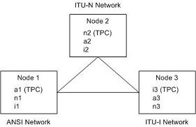
The node’s true point code is also called the destination point code.
This chapter discusses the method for configuring destination point codes (DPCs) in the database of the EAGLE. Destination point codes can be one of five types:
- Full point codes used for SS7 routing. A full point code is a point code containing numbers in each portion of the point code, for example, 111-011-100. The full point code can be in one of three formats, ANSI, ITU international, or ITU national. See the Point Code Formats section for more information on the point code formats. The EAGLE must have a full point code for each network type (ANSI, ITU-N, ITU-I) it is connected to.
- Secondary point codes, used by the Multiple Point Code Support feature. A secondary point code is a point code assigned to a full point code and used as if they were the actual EAGLE point code. Secondary point codes can be in one of three formats: ANSI, ITU international, or ITU national. The format of the secondary point code must be the same as the format of the full destination point code. See the Multiple Point Code Support section for more information on secondary point codes.
- Cluster destination point codes, used by the cluster routing and management (CRMD) feature and nested cluster routing feature. A cluster point code is an ANSI point code containing numbers in the network identifier and network cluster portions of the point code, and an asterisk (*) in the network cluster member field of the point code, for example, 111-011-*. See the Cluster Routing and Management Diversity (CRMD) section and the Nested Cluster Routing section for more information on cluster point codes.
- Network routing point codes, used by the network routing feature. A network routing point code is an ANSI point code containing a number in the network identifier portion of the point code, and asterisks (*) in the network cluster and network cluster member portions of the point code, for example, 111-*-*. See the Network Routing section for information on network routing point codes.
- Proxy point codes, used by the Proxy Point Code feature. A proxy point code is a point code that assumes the point code of another node in order to ease the migration of deploying an STP in a network with direct-connect links into other networks. See the Proxy Point Codes section for more information about proxy point codes.
The Cluster Routing and Management Diversity (CRMD) feature, the nested cluster routing feature, the multiple point code support feature, and the network routing features are also discussed in this section.
In order to complete the definition of linksets and routes, destination point codes are required to be in the database. Even though linksets use adjacent point codes, the adjacent point code of a linkset must be defined in the destination point code table of the database.
The procedures shown in this chapter use a variety of commands. If more information on these commands is needed, go to Commands User's Guide to find the required information.
2.2 Point Code Formats
The EAGLE supports three different point code formats:
- ANSI point codes
- ITU International point codes
- ITU National point codes (both 14-bit ITU-N point codes and 24-bit ITU-N point codes).
ANSI Point Codes
ANSI point codes are made up of three groups of digits called the network indicator (NI), network cluster (NC), and network cluster member (NCM). The values for ANSI point codes depends on the value of the pctype parameter of the chg-sid command, either ansi or other. If the pctype parameter is set to ansi, the ANSI rules for the ANSI point code are used to define the point code. The range of values for an ANSI point code with the pctype=ansi parameter are:
- NI – 001-255
- NC – 001-255 (if ni = 001-005) or 000-255, * (if ni = 006-255)
- NCM – 000-255, *
The pctype=other parameter specifies that the ANSI point codes do not meet ANSI standards. The range of values for ANSI point codes with the pctype=other parameter are:
- NI – 000-255
- NC – 000-255, *
- NCM – 000-255, *
The asterisk (*) point code value indicates a single cluster address for a cluster point code (for example, 20-2-*) or a network routing destination (21-*-*). for more information on cluster point codes, see the Cluster Routing and Management Diversity (CRMD) section. For more information on network routing point codes, see the Network Routing section.
A double asterisk (**) and triple asterisk (***) can also be used for the NC and NCM fields of the ANSI point code, but for only the rtrv-dstn, rept-stat-dstn, rtrv-rte, and rept-stat-rte commands.
A double asterisk in the NCM field of a point code (for example, 20-2-**) produces a summary report that shows all point code destinations or routes residing in the given cluster (20-2). This does not include the cluster point code, if the cluster point code (for example, 20-2-*) is provisioned. The following examples (rtrv-dstn and rtrv-rte) are reports generated using two asterisks in the NCM field of a point code.
rtrv-dstn:dpca=20-2-**
rlghncxa03w 09-05-28 21:16:37 GMT EAGLE5 41.0.0
    DPCA          CLLI        BEI ELEI   ALIASI          ALIASN/N24    DMN
    020-002-045   rlghncbb100 no  --- ----------      --------------   SS7
    020-002-050   rlghncbb100 no  --- ----------      --------------   SS7

Destination table is (11 of 2000) 1% full
Alias table is (5 of 8000) 1% full
rtrv-rte:dpca=20-2-**
rlghncxa03w 07-05-28 21:16:37 GMT EAGLE5 37.0.0
   DPCA           ALIASI     ALIASN/N24    LSN        RC    APCA
   020-002-045 ---------- --------------   lsn1       15    020-002-045
                                           lsn2       20    020-003-036
                                           lsn3       25    001-001-002
                                               RTX:No  CLLI=-----------
   020-002-050 ---------- --------------   lsn4       15    020-002-050
                                           lsn3       20    001-001-002
                                           lsn2       25    020-003-036
                                               RTX:No  CLLI=-----------
A double asterisk in the NC field of a network routing point code (for example, 21-**-*) produces a summary report that shows all point code destinations or routes that are members of the given network (network 21). This does not include the specified network routing point code (for example, 21-*-*). The following examples (rtrv-dstn and rtrv-rte) are reports using two asterisks in the NC field of a network routing point code.
rtrv-dstn:dpca=21-**-*
rlghncxa03w 09-05-28 21:16:37 GMT EAGLE5 41.0.0
    DPCA          CLLI        BEI ELEI   ALIASI          ALIASN/N24    DMN
    021-002-045   rlghncbb101 no  --- ----------      --------------   SS7
    021-002-050   rlghncbb101 no  --- ----------      --------------   SS7

Destination table is (11 of 2000) 1% full
Alias table is (5 of 8000) 1% full
rtrv-rte:dpca=21-**-*
rlghncxa03w 07-05-28 21:16:37 GMT EAGLE5 37.0.0
   DPCA           ALIASI     ALIASN/N24    LSN        RC    APCA
   021-002-045 ---------- --------------   lsn10      15    021-002-045
                                           lsn20      20    021-003-036
                                           lsn30      25    010-001-002
                                               RTX:No  CLLI=-----------
   021-002-050 ---------- --------------   lsn40      15    021-002-050
                                           lsn30      20    010-001-002
                                           lsn20      25    021-003-036
                                               RTX:No  CLLI=-----------
   021-005-*   ---------- --------------   lsn40      15    021-002-050
                                           lsn30      20    010-001-002
                                           lsn20      25    021-003-036
                                               RTX:No  CLLI=-----------
Three asterisks in the NCM field of a point code produces a summary report that shows all point code destinations or routes residing in the given network cluster along with the specified cluster point code, if the cluster point code (for example, 20-2-*) is provisioned. The following examples (rtrv-dstn and rtrv-rte) are reports using three asterisks in the NCM field of a point code.
rtrv-dstn:dpca=20-2-***
rlghncxa03w 09-05-17 16:00:32 GMT  EAGLE5 41.0.0
    DPCA          CLLI        BEI ELEI   ALIASI          ALIASN/N24    DMN
    020-002-*     rlghncbb000 no  --- ----------      --------------   SS7
    020-002-045   rlghncbb100 no  --- ----------      --------------   SS7
    020-002-050   rlghncbb100 no  --- ----------      --------------   SS7

Destination table is (11 of 2000) 1% full
Alias table is (5 of 8000) 1% full
rtrv-rte:dpca=20-2-***
rlghncxa03w 07-05-28 21:16:37 GMT EAGLE5 37.0.0

   DPCA           ALIASI     ALIASN/N24    LSN        RC    APCA
   020-002-045 ---------- --------------   lsn1       15    020-002-045
                                           lsn2       20    020-003-036
                                           lsn3       25    001-001-002
                                               RTX:No  CLLI=-----------
   020-002-050 ---------- --------------   lsn4       15    020-002-050
                                           lsn3       20    001-001-002
                                           lsn2       25    020-003-036
                                               RTX:No  CLLI=-----------
   020-002-*   ---------- --------------   lsn4       15    020-002-050
                                           lsn3       20    001-001-002
                                           lsn2       25    020-003-036
                                               RTX:No  CLLI=-----------
Three asterisks in the NC field of the point code produces a summary report that shows all point code destinations or routes residing in the given network along with the specified network routing point code. The following examples (rtrv-dstn and rtrv-rte) are reports using three asterisks in the NC field of a network routing point code.
rtrv-dstn:dpca=21-***-*
rlghncxa03w 09-05-17 16:00:32 GMT  EAGLE5 41.0.0
    DPCA          CLLI        BEI ELEI   ALIASI          ALIASN/N24    DMN
    021-*-*       rlghncbb001 yes yes ----------      --------------   SS7
    021-002-045   rlghncbb101 no  --- ----------      --------------   SS7
    021-002-050   rlghncbb101 no  --- ----------      --------------   SS7

Destination table is (11 of 2000) 1% full
Alias table is (5 of 8000) 1% full
rtrv-rte:dpca=21-***-*
rlghncxa03w 07-05-28 21:16:37 GMT EAGLE5 37.0.0

   DPCA           ALIASI     ALIASN/N24    LSN        RC    APCA
   021-002-045 ---------- --------------   lsn10      15    021-002-045
                                           lsn20      20    021-003-036
                                           lsn30      25    010-001-002
                                               RTX:No  CLLI=-----------
   021-002-050 ---------- --------------   lsn40      15    021-002-050
                                           lsn30      20    010-001-002
                                           lsn20      25    021-003-036
                                               RTX:No  CLLI=-----------
   021-005-*   ---------- --------------   lsn40      15    021-002-050
                                           lsn30      20    010-001-002
                                           lsn20      25    021-003-036
                                               RTX:No  CLLI=-----------
   021-*-*     ---------- --------------   lsn30      20    010-001-002
                                           lsn20      25    021-003-036
                                           lsn40      35    021-002-050
                                               RTX:No  CLLI=-----------
The following rules apply to provisioning ANSI point code if the pctype=ansi parameter is specified with the chg-sid command:
- The NI value of 0 is not allowed (for example,
dpc=0-1-1anddpc=0-0-0are not valid point codes). - If the NI value is 1, 2, 3, 4, or 5, then the nc value cannot be 0 (for example,
dpc=5-0-1is rejected). - If the NI value is 1, 2, 3, 4, or 5, then network routing point codes are not allowed (for example,
dpc=4-*-*is rejected).
The following rules apply to provisioning ANSI point code if the pctype=other parameter is specified with the chg-sid command:
- The NI value of 0 is allowed, however
dpc=0-0-0is rejected (for example,dpc=0-1-1is accepted). - The NC value can be 0 for all values of NI (for example,
dpc=5-0-1is accepted). - Network routing point codes are allowed for all values of ni (for example,
dpc=4-*-*is accepted).
An ANSI point code containing all zeros is not a valid point code and cannot be entered into the database.
ITU International Point Codes
The ITU international point codes are made up of three groups of digits called zone, area, and id. The range of values for ITU International point codes are:
- ZONE – 0-7
- AREA – 000-255
- ID – 0-7
An ITU international point code containing all zeros is not a valid point code and cannot be entered into the database.
14-Bit ITU National Point Codes
The 14-bit ITU national point code is either a 1- to 5-digit number, or 2, 3, or 4 numbers separated by dashes. 14-bit ITU national point codes can also have group codes assigned to them if the ITU National Duplicate Point Code feature is on. The group code is a two-character field ranging from AA to ZZ that is entered as the last subfield of a 14-bit ITU national point code and is separated by a dash from the rest of the point code. If the ITU National Duplicate Point Code feature is on, the format of a 14-bit ITU national point code is either a 1- to 5-digit number with a group code (for example, 11567-aa), or 2, 3, or 4 numbers separated by dashes with a group code (for example, 5-15-10-3-aa).
For more information on the format of 14-bit ITU national point code formats, see the 14-Bit ITU National Point Code Formats section.
For more information on the ITU National Duplicate Point Code feature and group codes, see the ITU National Duplicate Point Codes section.
24-Bit ITU National Point Codes
A 24-bit ITU national point code is made up of three segments separated by dashes. Each segment contains three digits and corresponds to 8 bits of the point code. The range of values for 24-bit ITU national point codes are:
- Main Signaling Area (MSA) – 000-255
- Sub Signaling Area (SSA) – 000-255
- Signaling Point (SP) – 000-255
A 24-bit ITU international point code containing all zeros is not a valid point code and cannot be entered into the database.
Spare Point Codes
The provisioning of spare point codes allows the EAGLE to process messages that contain either the International Spare or National Spare network indicator values. Spare point codes can be provisioned only if the ITU National and International Spare Point Code (PC) Support feature is enabled. Only ITU-I and 14-bit ITU-N point codes can be provisioned as spare point codes.
Spare point codes are shown with the prefix “s-” with the point code value. This allows the destination point code table to contain two point code entries with the same value, one a spare point code and one a non-spare point code. For example, the destination point code table contains these point code entries, 2-034-5 and s-2-034-5. Point code 2-034-5 is a non-spare ITU-I point code and point code s-2-034-5 is a spare ITU-I point code.
Private Point Codes
Private point codes are used for internal routing in the EAGLE 5 ISS. Private point codes can be used for internal point codes for the End Office feature, and for adjacent point codes for IPGWx linksets.
Private point codes are shown with the prefix “p-” with the point code value. This allows the destination point code table to contain two point code entries with the same value, one private and one not private. For example, the destination point code table contains these point code entries, 002-002-002 and p-002-002-002. Point code 002-002-002 is a non-private point code that is used for configuring linksets and routes from the EAGLE 5 ISS to external nodes in the network. Point code p-002-002-002 is a private point code and is not known to the external nodes in the network.
By using private point codes for internal routing, these point code values are not known outside of the EAGLE 5 ISS and do not use a point code value for network configuration.
There can be private point codes for all point code types: ANSI, ITU-I, ITU-I Spare, 14-bit ITU-N, 14-bit ITU-N Spare, and 24-bit ITU-N.
Point Code Usage
The ANSI are used in ANSI networks. The ITU international point codes are used in ITU international networks. The ITU national point codes are used in ITU national networks. ITU national point codes can be either 14-bit ITU national point codes, or 24-bit ITU national point codes. Table 2-1 shows a sample destination point code for each type of network.
Table 2-1 Point Code Format
| Network Type | Point Code Format |
|---|---|
|
ANSI |
001-002-003 |
|
ITU International |
7-255-7 |
|
14-bit ITU National |
|
|
24-bit ITU National |
001-002-003 |
To enter an ITU international point code, a 14-bit ITU national point code or a 24-bit ITU national point code, either as a DPC or as an alias point code, the self ID of the EAGLE must be defined for these networks. Verify this with the rtrv-sid command. If point code values are shown in the PCI field of the output of the rtrv-sid command, then ITU international point codes can be entered. If point code values are shown in the PCN field of the output of the rtrv-sid command, then the 14-bit ITU national point codes can be entered. If point code values are shown in the PCN24 field of the output of the rtrv-sid command, then 24-bit ITU national point codes can be entered. If a value is shown in the PCN field, then a value cannot be entered in the PCN24 field. If a value is shown in the PCN24 field, then a value cannot be entered in the PCN field.
A destination is defined with a mandatory true point code of one format, and two optional alias point codes that are of the other two formats. Alias point codes are used to provide alternate point codes for a particular destination. The true point code must be of the same format as the point code used for the self ID of the EAGLE and must match the format of the point code used for the destination node. For example, if the destination node uses an ANSI point code, then the true point code must be an ANSI point code.
A destination can have up to two alias point codes. A destination alias point code type must not match that destination's true point code type. If both alias point codes are defined, the point code types of the aliases must not match.
The point code type (ANSI, ITU international, ITU national) is specified by different parameters. A letter that indicates the point code type is appended to the parameter that specifies the point codes. The appended letters are as follows.
“A” – indicates an ANSI point code, for example, dpca
“I” – indicates an ITU international point code, for example, dpci
“N” – indicates a 14-bit ITU national point code, for example, dpcn
“N24” – indicates a 24-bit ITU national point code, for example, dpcn24
The ANSI point codes can also be specified by a point code parameter without the letter “A” appended to it, for example, dpc.
2.3 14-Bit ITU National Point Code Formats
The format of a 14-bit ITU national point code is defined by the npcfmti parameter of the chg-stpopts command. This parameter defines how the 14-bit ITU national point code is entered into the database, and how it is displayed in any EAGLE outputs (command outputs or unsolicited outputs).
The 14-bit ITU national point code can be either a single number, up to five digits, or two, three, or four numbers separated by dashes. The 14-bit ITU national point code is a 14-bit integer. The values used by the npcfmti parameter of the chg-stpopts command defines the number of bits that make up each part of the point code format, if the 14-bit ITU national point code is made up of two, three, or four numbers.
If the 14-bit ITU national point code format has less than four numbers, the parts of the point code format not being used must be specified as zero (0). All four parts of the point code format must be specified with the npcfmti parameter, no matter how many numbers the point code format will contain, and the sum of the values of all four parts of the point code format must be 14 (for example, NPCFMTI=7-7-0-0, NPCFMTI=0-6-8-0, NPCFMTI=0-0-4-10, NPCFMTI=3-8-3-0, NPCFMTI=14-0-0-0).
If the database contains 14-bit ITU national point codes of a particular format, and the format is changed with the npcfmti parameter of the chg-stpopts command, the format of the 14-bit ITU national point codes in the database will be changed to the new format.
The values of the parts of the 14-bit ITU national point code are defined in Table 2-2.
Table 2-2 14-Bit ITU National Point Code Values
|
NPCFMTI Parameter Values |
0 |
1 |
2 |
3 |
4 |
|
Range of Values |
The segment is not used. |
0–1 |
0–3 |
0–7 |
0–15 |
|
NPCFMTI Parameter Values |
5 |
6 |
7 |
8 |
9 |
|
Range of Values |
0–31 |
0–63 |
0–127 |
0–255 |
0–511 |
|
NPCFMTI Parameter Values |
10 |
11 |
12 |
13 |
14 |
|
Range of Values |
0–1023 |
0–2047 |
0–4095 |
0–8191 |
0–16383 |
A 14-bit ITU national point code containing all zeros is a valid point code and can be entered into the database.
When the EAGLE is delivered to the user, the format of the 14-bit ITU national point code is set to 14-0-0-0 (a single number containing up to five digits). If the 14-bit ITU national point code is a single number, the value of the point code is from 1 to 16383.
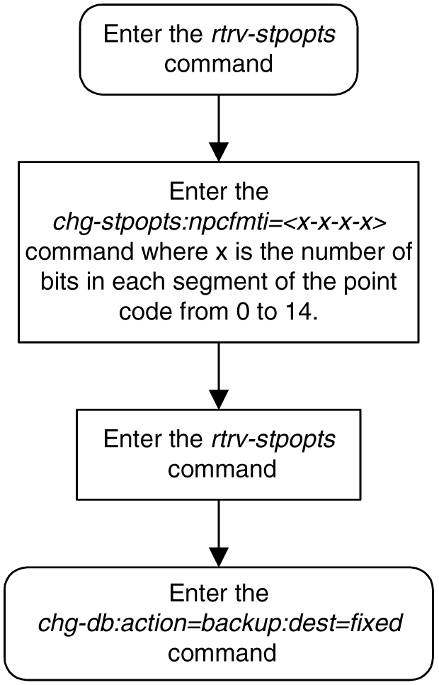
To change the format of a 14-bit ITU national point code, perform Changing the Format of 14-Bit ITU National Point Codes. The example used in this procedure changes the format of the 14-bit ITU national point code from 14-0-0-0 to 4-4-4-2.
Changing the Format of 14-Bit ITU National Point Codes
Caution:
Changing the formats of the 14-bit ITU national point codes will change how any existing 14-bit ITU national point codes are displayed in the database.- Display the existing values for the
npcfmtiparameter by entering thertrv-stpoptscommand. The value for thenpcfmtiparameter is shown in theNPCFMTIfield. This is an example of the possible output.rlghncxa03w 07-05-17 16:02:05 GMT EAGLE5 37.0.0 STP OPTIONS ----------------------- NPCFMTI 14-0-0-0Note:
Thertrv-stpoptscommand output contains other fields that are not used by this procedure. If you wish to see all the fields displayed by thertrv-stpoptscommand, see thertrv-stpoptscommand description in Commands User's Guide. - Change the value of the
npcfmtiparameter. For this example, enter this command.chg-stpopts:npcfmti=4-4-4-2When this command has successfully completed, this message should appear.
rlghncxa03w 07-05-07 00:22:57 GMT  EAGLE5 37.0.0
CHG-STPOPTS: MASP A - COMPLTD
Note:
The parameters of thechg-stpoptscommand are optional. For any parameters not specified with thechg-stpoptscommand, the values for these parameters are not changed. - Verify the changes using the
rtrv-stpoptscommand. This is an example of the possible output.rlghncxa03w 07-05-17 16:02:05 GMT EAGLE5 37.0.0 STP OPTIONS ----------------------- NPCFMTI 4-4-4-2Note:
Thertrv-stpoptscommand output contains other fields that are not used by this procedure. If you wish to see all the fields displayed by thertrv-stpoptscommand, see thertrv-stpoptscommand description in Commands User's Guide. - Back up the new changes, using the
chg-db:action=backup:dest=fixedcommand. These messages should appear; the active Maintenance and Administration Subsystem Processor (MASP) appears first.BACKUP (FIXED) : MASP A - Backup starts on active MASP. BACKUP (FIXED) : MASP A - Backup on active MASP to fixed disk complete. BACKUP (FIXED) : MASP A - Backup starts on standby MASP. BACKUP (FIXED) : MASP A - Backup on standby MASP to fixed disk complete.Figure 2-2 Changing the Format of an ITU National Point Code
Examples of Different 14-Bit ITU National Point Code Formats
A 14-bit ITU national point code whose format is 3-8-3-0, results in a point code containing three numbers separated by dashes. Because the fourth part of the format is zero, the point code format contains only three numbers. Using Table 2-2 as a guide, the range of values for this point code format are from 0-000-1 to 7-255-7.
A 14-bit ITU national point code whose format is 2-8-3-1, results in a point code containing four numbers separated by dashes. Using Table 2-2 as a guide, the range of values for this point code format are from 0-000-0-1 to 3-255-7-1.
A 14-bit ITU national point code whose format is 7-0-7-0 results in a point code containing two numbers separated by dashes. Because the second and fourth parts of the format are zero, the point code format contains only two numbers. Using Table 2-2 as a guide, the range of values for this point code format are from 000-001 to 127-127.
A 14-bit ITU national point code whose format is 14-0-0-0 results in a point code containing a single number, containing up to five digits. Using Table 2-2 as a guide, the range of values for this point code format are from 1 to 16383.
Exception
The format defined by the npcfmti parameter of the chg-stpopts command applies to all database entities that use 14-bit ITU national point codes, except gateway screening. Gateway screening allows the 14-bit ITU national point code to be displayed and entered in the database only as a single number. If the EAGLE 5 ISS is using a format for the 14-bit ITU national point code other than a single number, the point code will have to be converted from its current format to a single number in order to be used by gateway screening.
Converting Single Number 14-Bit ITU National Point Codes
To convert a single number ITU national point code to a multiple part ITU national point code, perform these steps. For this example, the 14-bit ITU national point codes 14781 and 695 are converted to point codes using the 3-8-3-0 format.
- The point code is converted to a binary number. This can be done with most scientific calculators.
- The number 14781 converts to the binary number 11100110111101.
- The number 695 converts to the binary number 1010110111.
Note:
Make sure the binary number contains 14 digits. If it does not, add leading zeros to the binary number to bring the total number of digits in the number to 14.In this example, the binary equivalent for the decimal number 695 (1010110111) contains 10 digits, so four zeros must be added to the beginning of the binary number. The resulting binary number is now 00001010110111.
- Divide the binary number into the number of parts required by the format of the 14-bit ITU national point code. For this example, the format is 3-8-3-0. Since the last part of the point code format is 0, the point code format contains only three parts. Divide the point code into three parts: the first part of the point code contains the first three digits of the 14-digit binary number, the second part of the point code contains the next eight digits of the 14-digit binary number, and the third part of the point code contains the last three digits of the 14-digit binary number.
For this example, the binary numbers would be divided like this:
- 11100110111101 = 111 00110111 101
- 00001010110111 = 000 01010110 111
- Convert each part of the point code into a decimal number, using the same scientific calculator used in step 1, and separate each part of the point code with dashes. The results are as follows.
- 111 00110111 101 = 7-55-5
- 000 01010110 111 = 0-86-7
When the 14-bit ITU national point codes are converted from single numbers to multiple-part point codes, the resulting value of the multiple-part point code depends on the point code format specified by the npcfmti parameter of the chg-stpopts command. When converting the single-number point code 14781 to the point code format 3-8-3-0, the resulting point code value is 7-55-5. If point code 14781 is converted to the point code format 4-4-4-2, the resulting point code value is 14-6-15-1.
Converting Multiple-Part 14-Bit ITU National Point Codes
To convert multiple-part 14-bit ITU national point codes to a single number, perform these steps. For this example, the 14-bit ITU national point codes 7-55-5 and 0-86-7, using the 3-8-3-0 point code format, are converted into a single number.
- Convert each part of the point code into a binary number using a scientific calculator. The results are as follows.
- 7-55-5 = 111 00110111 101
- 0-86-7 = 000 01010110 111
- Combine each part of the point code into a single binary number as follows.
- 111 00110111 101 = 11100110111101
- 000 01010110 111 = 00001010110111
Note:
If the binary number has any zeros at the beginning of the number, remove these zeros, as they are not necessary.In this example, the binary equivalent for the point code 0-86-7 (00001010110111) contains four zeros at the beginning of the binary number. When the leading zeros are removed from the binary number, the resulting binary number is now 1010110111.
- Convert the binary number to a decimal number using the same scientific calculator used in step 1.
- The binary number 11100110111101 converts to the decimal number 14781.
- The binary number 1010110111 converts to the decimal number 695.
2.4 ITU National Duplicate Point Codes
Note:
This feature applies only to 14-bit ITU national spare and non-spare point codes.
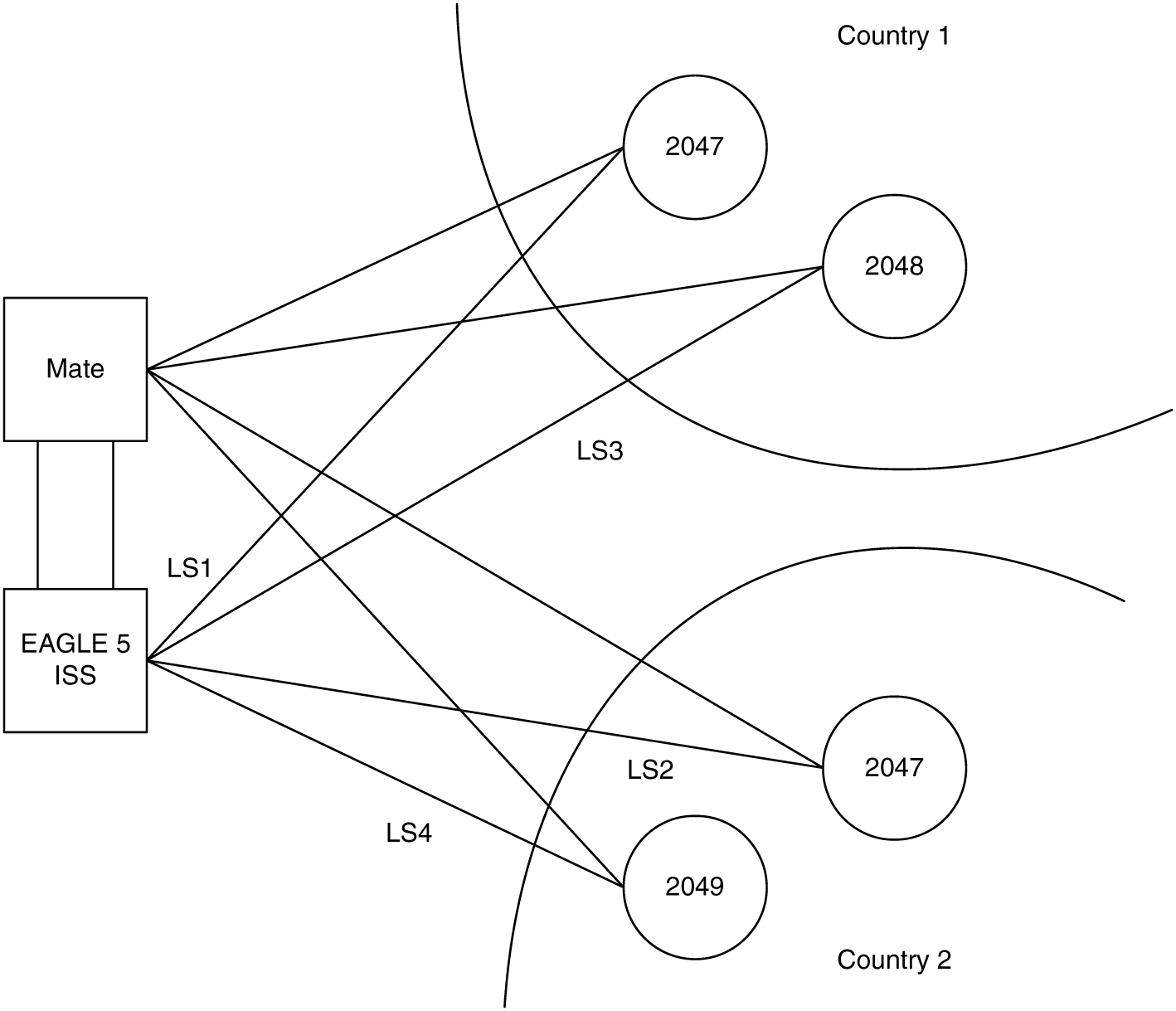
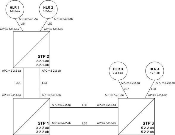
This feature allows an EAGLE mated pair to route traffic for two or more countries that may have overlapping point code values. For example, in the network shown in Figure 2-3, both Country 1 and Country 2 have SSPs with a PC value of 2047.
Figure 2-3 Network Example #1
Group Codes
Users must divide their ITU-National destinations into groups. These groups will likely be based on Country. However, one group could have multiple countries within it, or a single country could be divided into multiple groups. The requirements for these groups are:
- No duplicate point codes are allowed within a group.
- ITU-National traffic from a group must be destined for a PC within the same group.
- The user must assign a unique two-letter group code to each group.
For example, in the network shown in Figure 2-4, Country 1 can only have 1 point code with a value of 2047. Traffic coming from SSP 2047 in Country 1 can only be destined to other nodes within Country 1. In this example, the user assigns a group code of 1 to Country 1, and a group code of 2 to Country 2.
When the user enters an ITU-National point code, they must also enter the group code, using the format “point code - group code”. This group code must be used for any command that uses an ITU-N point code.
For example, to provision the EAGLE for the network shown in Figure 2-4, the user would enter these commands:
ent-dstn:dpcn=2047-aa
ent-dstn:dpcn=2048-aa
ent-dstn:dpcn=2047-ab
ent-dstn:dpcn=2049-ab
ent-ls:lsn=LS1:apcn=2047-aa
ent-ls:lsn=LS2:apcn=2047-ab
ent-ls:lsn=LS3:apcn=2048-aa
ent-ls:lsn=LS4:apcn=2049-ab
Group Code aa
The following special rules apply to group code aa:
- ITU-N MSUs received on an ITU-I linkset are assigned group code of aa.
- ITU-N destinations entered before this feature is turned on are assigned group code of aa when the ITUDUPPC feature bit is turned on.
Normal Operation
When an ITU-N message arrives at the EAGLE, the EAGLE creates an internal point code based on the 14 bit PC in the message, and the group code assigned to the incoming linkset.
For example, when a message arrives on LS3 with DPC of 2047, the EAGLE maps that to an internal point code of 2047-aa, because LS3 has a group code of aa. The EAGLE then routes the message to LS1, which is the route for 2047-aa.
When a message arrives on LS4 with DPC of 2047, the EAGLE maps that to an internal point code of 2047-ab, because LS4 uses group code ab. The EAGLE then routes the message to LS2, which is the route for 2047-ab.
C Linksets
For each group defined, a separate C-linkset must be defined. This C-linkset is used as the alternate route for point codes in the group.
For example, in Figure 2-4, LSC1 is used for point codes in Group fr. Its adjacent point code is 6201-fr, and is used as the alternate route for 6217-fr, 6218-fr, and 6223-fr.
LSC2 is used for point codes in Group ge. Its adjacent point code is group 4169-ge, and is used as the alternate route for 6200-ge, 6209-ge, and 6217-ge.
Figure 2-4 Network Example #2
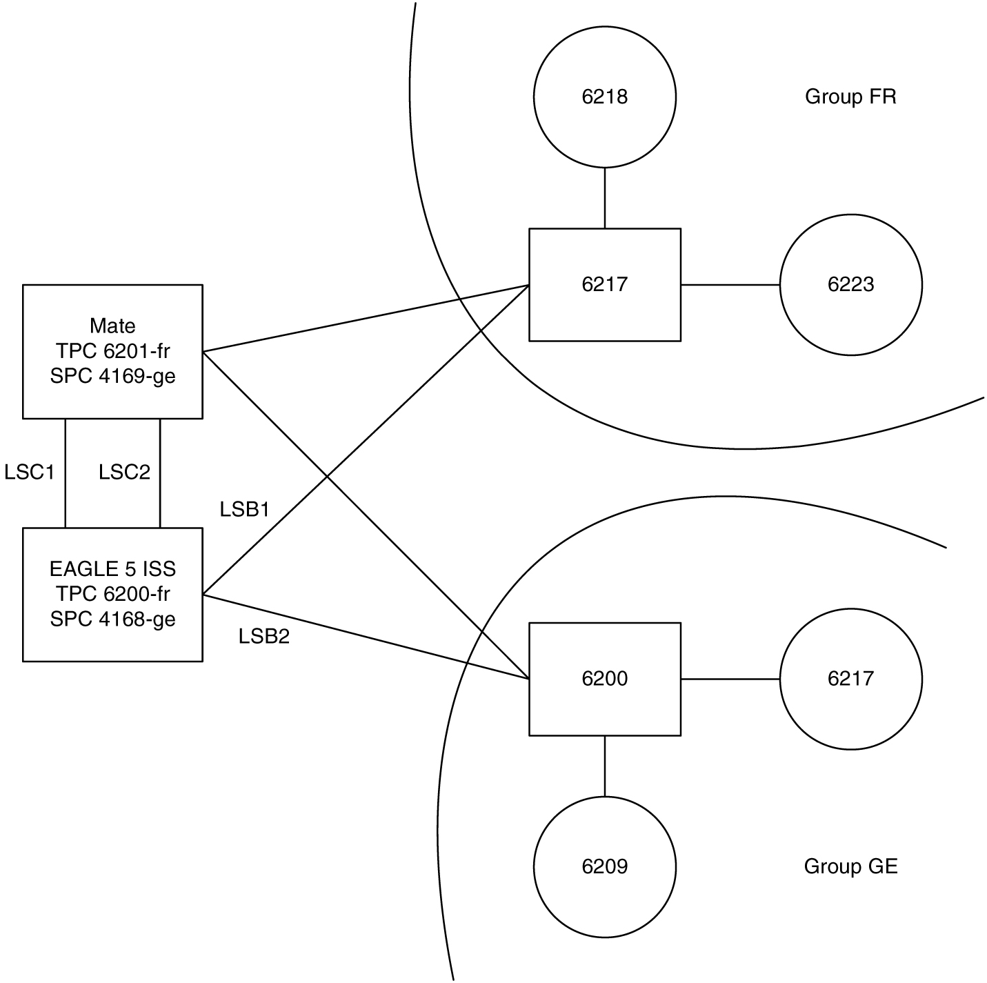
For example, to provision the EAGLE for the network shown in Figure 2-5, the user would enter these commands:
ent-dstn:dpcn=6201-fr (Mate's true PC)
ent-dstn:dpcn=4169-ge (Mate's secondary PC)
ent-dstn:dpcn=6217-fr (Group fr destinations)
ent-dstn:dpcn=6218-fr
ent-dstn:dpcn=6223-fr
ent-dstn:dpcn=6200-ge (Group ge destinations)
ent-dstn:dpcn=6217-ge
ent-dstn:dpcn=6209-ge
ent-ls:lsn=LSC1:apcn=6201-fr:lst=C (C linkset used by Group fr)
ent-ls:lsn=LSC2:apcn=4169-ge:lst=C (C linkset used by Group ge)
ent-ls:lsn=LSB1:apcn=6217-fr:lst=B
ent-ls:lsn=LSB2:apcn=6200-ge:lst=B
ent-rte:dpcn=6217-fr:lsn=LSB1:rc=10 (primary route for a Group fr destination)
ent-rte:dpcn=6217-fr:lsn=LSC1:rc=20 (alternate route for a Group fr destination)
ent-rte:dpcn=6217-ge:lsn=LSB2:rc=10 (primary route for a Group ge destination)
ent-rte:dpcn=6217-ge:lsn=LSC2:rc=20 (alternate route for a Group ge destination)
Receiving an ITU-National MSU on an ITU-International Linkset
It is possible for the EAGLE to receive ITU-National MSUs on an ITU-International linkset. A linkset is considered an ITU-International linkset if it's adjacent point code is an ITU-International PC. An MSU is ITU-National if it is received on an ITU linkset (National or International), and the NIC field in the SIO is set to 2 (National).
ITU-International linksets do not have a group code. ITU-National MSUs received on ITU-International linksets will be assigned a group code of aa.
Existing ITU National Destinations
Any ITU-National destinations that were entered before Release 26.05 or before the ITU National Duplicate Point Codes feature was turned on will be assigned the group code of aa.
Interaction with Other Features
Gateway Screening
For example, in the network in Figure 2-4, if the user wanted to screen out MSU coming from 6217 in Group ge, but allow MSUs coming from 6217 in Group fr, he or she could assign different screensets to LSB1 and LSB2. The screenset assigned to LSB1 would allow MSUs from OPC 6217. The screenset assigned to LSB2 would block MSUs from OPC 6217.
Multiple Point Codes
The Multiple Point Codes feature (see “Multiple Point Code Support”) must be on in order to turn on the ITU National Duplicate Point Codes feature. For every group that is used, the user must provision either a True PC or Secondary Point Code, using the chg-sid command.
For example, in the network in Figure 2-4, two groups are used having group codes of fr and ge. An ITU-National True Point Code is entered for group fr, and an ITU-National Secondary Point code is entered for group ge.
Conversion between ITU-N and ITU-I or ANSI
Each ITU-N destination and group code can have its own ITU-I or ANSI alias PC. Each ITU-I or ANSI node can be assigned one ITU-N destination. For conversion from ITU-I or ANSI to ITU-N to succeed, the ITU-N alias of the sending node must have the same group code as the destination's group code. So each ITU-I or ANSI node can only send and receive messages from one ITU-N group.
Figure 2-5 Network for Conversion
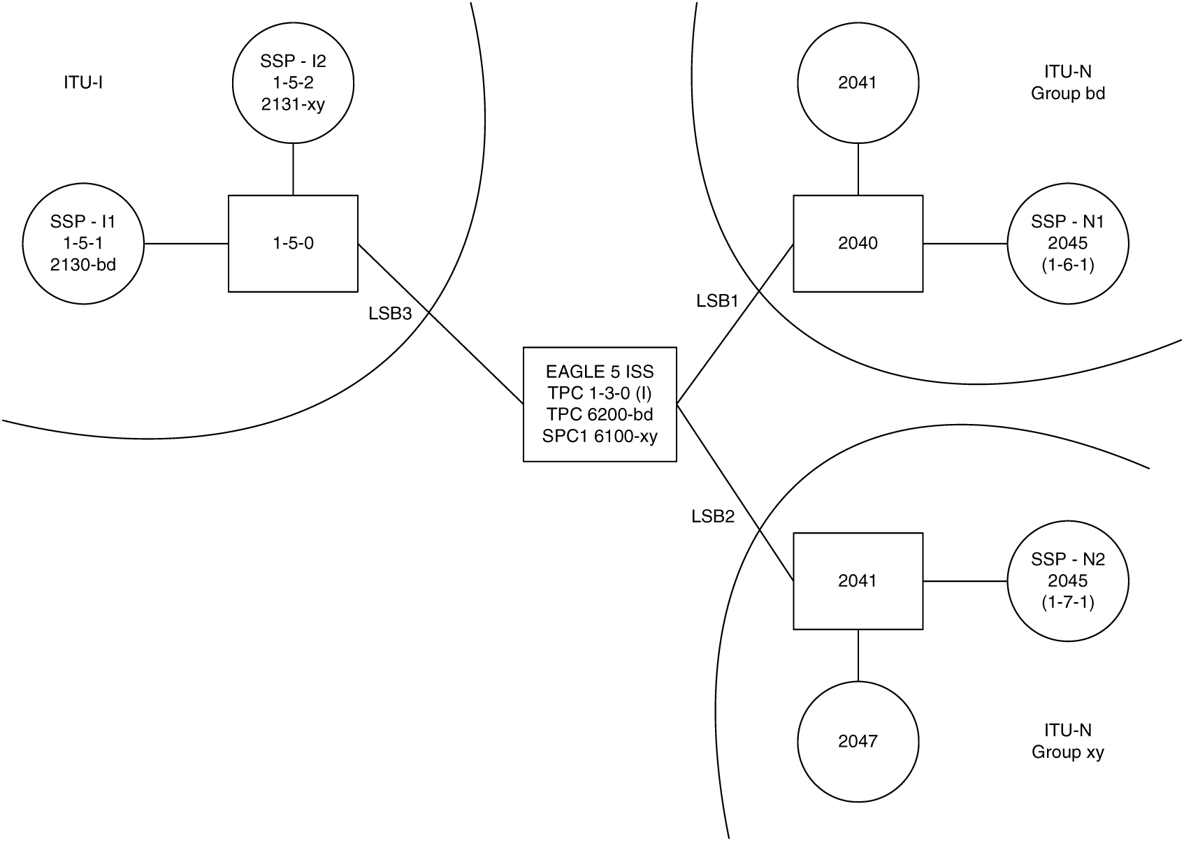
In Figure 2-5, SSP-N1 (2045-bd) is assigned ITU-I alias 1-6-1, and SSP-N2 (2045-xy) is assigned ITU-I alias 1-7-1. SSP-I1 is assigned ITU-N alias 2130-bd and SSP-I2 is assigned ITU-N alias 2131-xy. In this example, SSP-I1 can exchange traffic with nodes in group bd, but not nodes in group xy. SSP-I2 can exchange traffic with nodes in group xy, but not nodes in group bd.
SSP-I1 (1-5-1) can send to SSP-N1 by using the ITU-I alias 1-6-1, But if SSP-I1 tries to send to 2045-xy by using the ITU-I alias 1-7-1, conversion will fail, and the EAGLE will generate UIM 1091 (Indicating OPC conversion failed).
SSP-N1 can send traffic to SSP-I1, but SSP-N2 cannot send traffic to SSP-I1. SSP-N1 sends an ITU-N MSU with DPC set to 2130. The EAGLE assigns a group code of bd to the MSU based on the incoming linkset. The EAGLE then looks up 2130-bd, determines that this is an alias for ITU-I 1-5-1, and routes the MSU to SSP-I1.
If SSP-N2 sends an ITU-N MSU with DPC set to 2130, the EAGLE assigns a group code of xy to the MSU based on the incoming linkset. The EAGLE then looks up 2130-xy, does not find a match, and discards the MSU.
To provision the SSP-N1, SSP-N2, SSP-I1, and SSP-I2 in the network shown in Figure 2-5, the following commands are used:
ent-dstn:dpcn=2045-bd:aliasi=1-6-1
ent-dstn:dpcn=2045-xy:aliasi=1-7-1
ent-dstn:dpci=1-5-1:aliasn=2130-bd
ent-dstn:dpci=1-5-2:aliasn=2131-xy
ent-rte:dpcn=2045-bd:lsn=LSB1:rc=10
ent-rte:dpcn=2045-xy:lsn=LSB2:rc=10
ent-rte:dpci=1-5-1:lsn=LSB3:rc=10
ent-rte:dpci=1-5-2:lsn=LSB3:rc=10
Limitations
The ITU National Duplicate Point Code feature has the following limitations:
- Duplicate Point Codes are only supported for ITU-National Destinations.
- ITU-National traffic from a group must be destined for a PC within the same group.
- No duplicate point codes are allowed within a group.
- For each group that is provisioned, a separate ITU-N C-linkset must be provisioned.
- It is not possible to change a destination's group code. If the user wants to move a destination from one group to another, the user must provision a new destination that uses the new group code and delete the old destination.
- If conversion between ITU-N and ITU-I or ANSI is used, only 1 ITU-N group can send traffic to a specific ANSI or ITU-I node.
2.5 Proxy Point Codes
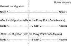
The Proxy Point Code feature allows the EAGLE to assume the point codes of other nodes in order to ease the migration of deploying an STP in a network with direct-connect links into other networks. For example, if a foreign network SS7 node is directly connected to an SS7 node in the home network, an EAGLE can be deployed so that the transition is transparent to the foreign node. The foreign node can still behave as if it is connected to the original node in the home network. EAGLE will provide routing connectivity in the home network to the foreign node and will allow the foreign node to connect to the home network.
In the examples in Figure 2-6, foreign network Node A connects to home network Node B. Normally, STP C would connect between them, requiring both Node A and Node B to use STP C as the APC. With this feature, Node A does not require any modifications, as STP C provides a proxy point code B. The configuration in this example assume that the self point code of the STP is C.
Figure 2-6 Context of the Proxy Point Code in the Network
A proxy point code can be any of these types of point codes:
- ANSI
- ITU-I
- ITU-I Spare
- 14-bit ITU-N
- 14-bit ITU-N Spare
- 24-bit ITU-N
A proxy point code must be a full point code and cannot be a cluster point code or a network routing point code. Private point codes and secondary point codes cannot be used as a proxy point code.
The following types of signaling links can be assigned to a linkset whose adjacent point code is a proxy point code:
- LSL
- ATM-HSL (LIM-ATM and E1-ATM are supported)
- SE-HSL
- M2PA.
Feature Provisioning Requirements
enable-ctrl-feat command and these part numbers shown in Table 2-3.
Table 2-3 Proxy Point Code Quantities and Part Numbers
| Part Number | Proxy Point Code Quantity |
|---|---|
| 893-0187-01 | 10 |
| 893-0187-02 | 20 |
| 893-0187-03 | 30 |
| 893-0187-04 | 40 |
| 893-0187-05 | 50 |
| 893-0187-06 | 60 |
| 893-0187-07 | 70 |
| 893-0187-08 | 80 |
| 893-0187-09 | 90 |
| 893-0187-10 | 100 |
Once a proxy point code quantity has been enable, the quantity cannot be decreased.
A temporary feature access key cannot be used to enabled a proxy point code quantity.
Once a proxy point code quantity has been enabled, the proxy point codes are provisioned in the database with the ent-dstn command and the prx parameter. Other point codes can use a proxy point code that is already provisioned in the database. These point codes are provisioned with the ent-dstn command and the ppc parameter.
After the proxy point code has been provisioned in the database, a linkset using the proxy point code can be provisioned in the database. This linkset, referred to as a proxy linkset, is provisioned using the ent-ls command with the adjacent point code of the linkset, the lst=prx parameter, and the ppc parameter. The ppc parameter value is the proxy point code provisioned with the ent-dstn command.
A proxy linkset has the same characteristics as an A linkset.
A proxy point code can be assigned to a maximum of 10 linksets.
Secondary adjacent point codes are not supported on a proxy linkset.
A proxy point code cannot be used as the adjacent point code of an IPGWx linkset.
To provision the Proxy Point Code feature, perform these procedures.
- Enable a proxy point code quantity using the
enable-ctrl-featcommand. Perform Changing the Proxy Point Code Quantity. Once a proxy point code quantity is enabled, the Proxy Point Code feature is enabled and turned on. Thechg-ctrl-featcommand cannot be used to turn the Proxy Point Code feature on. - Provision the proxy point code using the
ent-dstncommand with theprxandppcparameters. Perform Adding a Destination Point Code. - Provision the proxy linkset using the
ent-lscommand with thelst=prxandppcparameters. Perform Adding an SS7 Linkset .
2.6 Changing the Proxy Point Code Quantity
This procedure is used to increase the number of proxy point codes that are allowed in the EAGLE. The EAGLE can contain a maximum of 100 proxy point codes.
The enable-ctrl-feat command enables the proxy point code quantity, in groups of 10 proxy point codes, by specifying the part number for the proxy point code quantity and the proxy point code quantity’s feature access key with these parameters:
Note:
As of Release 46.3, the fak parameter is no longer required. This parameter is only used for backward compatibility.:fak- The feature access key supplied by Oracle. The feature access
key contains 13 alphanumeric characters and is not case sensitive. If you do not
have the feature access key for the proxy point code quantity you wish to enable,
contact your Oracle Sales Representative or Account Representative.
:partnum – The Oracle-issued part number for the proxy point code quantity shown in the following table:
Table 2-4 Proxy Point Code Quantities and Part Numbers
| Part Number | Proxy Point Code Quantity |
|---|---|
| 893018701 | 10 |
| 893018702 | 20 |
| 893018703 | 30 |
| 893018704 | 40 |
| 893018705 | 50 |
| 893018706 | 60 |
| 893018707 | 70 |
| 893018708 | 80 |
| 893018709 | 90 |
| 893018710 | 100 |
The enable-ctrl-feat command requires a valid serial number for the EAGLE to be configured in the database, and that this serial number is locked. This can be verified with the rtrv-serial-num command. The EAGLE is shipped with a serial number in the database, but the serial number is not locked. The serial number can be changed, if necessary, and locked once the EAGLE is on-site, by using the ent-serial-num command. The ent-serial-num command uses these parameters.
:serial – The serial number assigned to the EAGLE. The serial number
is not case sensitive.
:lock – Specifies whether or not the serial number is locked. This parameter has only one value, yes, which locks the serial number. Once the serial number is locked, it cannot be changed.
Note:
To enter and lock the EAGLE’s serial number, theent-serial-num command must be entered twice, once to add the correct serial number to the database with the serial parameter, then again with the serial and the lock=yes parameters to lock the serial number. You should verify that the serial number in the database is correct before locking the serial number. The serial number can be found on a label affixed to the control shelf (shelf 1100).
Once the proxy point code quantity is enabled with the enable-ctrl-feat command, the proxy point code is also turned on. The chg-ctrl-feat command is not necessary to turn on the proxy point code quantity.
Figure 2-7 Changing the Proxy Point Code Quantity
2.7 Changing the DPC Quantity
This procedure is used to increase the number of DPCs that are allowed in the EAGLE beyond what is currently shown in the ent-dstn, dlt-dstn, chg-dstn, and rtrv-dstn outputs. The EAGLE can contain a maximum of one of these quantities: 2000 (system default), 5000, 6000, 7000, 8000, or 10,000 DPCs.
To have more than 2000 DPCs in the EAGLE, the 5000 Routes feature must be turned on using the chg-feat command. Turning on the 5000 Routes features allows the EAGLE to contain a maximum of 5000 DPCs. To have more than 5000 DPCs in the EAGLE, either 6000, 7000, or 8000, or 10,000 routesets must be enabled using the enable-ctrl-feat command, in addition to having the 5000 Routes feature turned on. Enabling 6000, 7000, 8000, or 10,000 routesets allows the EAGLE to contain a maximum of 6000, 7000, 8000, or 10,000 DPCs. The rtrv-ctrl-feat command shows whether or not 6000, 7000, 8000, or 10,000 routesets are enabled. The rtrv-feat command shows whether or not the 5000 Routes feature is turned on.
Note:
Once the 5000 Routes feature is turned on with thechg-feat command, it cannot be turned off.
The 5000 Routes feature must be purchased before you turn this feature on with the chg-feat command. If you are not sure if you have purchased the 5000 Routes feature, contact your Oracle Sales Representative or Account Representative.
Once the maximum DPC quantity is set, the actual number of DPCs allowed in the EAGLE is configured using the mtpdpcq parameter of the chg-stpopts command. The rtrv-stpopts command output, as well as the outputs of the ent-dstn, dlt-dstn, chg-dstn, and rtrv-dstn commands, shows the actual number of DPCs allowed in the EAGLE.
If the Cluster Routing and Management Diversity feature is turned on, (shown by the entry CRMD = on in the rtrv-feat output) the mtpxlq parameter is also shown in the rtrv-stpopts output. The mtpxlq parameter defines the maximum number of entries that the exception list (x-list) for the Cluster Routing and Management Diversity feature can contain. The value of the mtpxlq parameter of the chg-stpopts command can also be changed to more than 2000 destination point codes. For more information on exception lists, see the "Exception Lists (X-lists)" in the Cluster Routing and Management Diversity (CRMD) section.
The enable-ctrl-feat command enables 6000, 7000, 8000, or 10,000 routesets by inputting the part number for the routeset quantity and the routeset quantity’s feature access key with these parameters.
:partnum – The Oracle-issued part number for the routeset quantity:
- For 6000 routesets - 893006401
- For 7000 routesets - 893006402
- For 8000 routesets - 893006403
- For 10,000 routesets - 893006405
:fak – The feature access key supplied by Oracle. The feature access key contains 13 alphanumeric characters and is not case sensitive.
Note:
The values for the feature access key (thefak parameter) are provided by Oracle. If you do not have the feature access key for the routeset quantity you wish to enable, contact your Oracle Sales Representative or Account Representative.
The enable-ctrl-feat command requires a valid serial number for the EAGLE to be configured in the database, and that this serial number is locked. This can be verified with the rtrv-serial-num command. The EAGLE is shipped with a serial number in the database, but the serial number is not locked. The serial number can be changed, if necessary, and locked once the EAGLE is on-site, by using the ent-serial-num command. The ent-serial-num command uses these parameters.
:serial – The serial number assigned to the EAGLE. The serial number is not case sensitive.
:lock – Specifies whether or not the serial number is locked. This parameter has only one value, yes, which locks the serial number. Once the serial number is locked, it cannot be changed.
Note:
To enter and lock the EAGLE’s serial number, theent-serial-num command must be entered twice, once to add the correct serial number to the database with the serial parameter, then again with the serial and the lock=yes parameters to lock the serial number. You should verify that the serial number in the database is correct before locking the serial number. The serial number can be found on a label affixed to the control shelf (shelf 1100).
To enable 7000 or 8000 routesets, the DPC table can contain no more than 8000 alias point codes. To enable 10,000 routesets, the DPC table can contain no more than 10,000 alias point codes. The number of alias point codes configured in the EAGLE is shown in the output of the ent-dstn, dlt-dstn, chg-dstn, and rtrv-dstn command outputs in one of two ways, depending on whether or not the Cluster Routing and Management Diversity feature is on or off.
If the Cluster Routing and Management Diversity feature is off.
rlghncxa03w 07-05-17 16:02:05 GMT  EAGLE5 37.0.0
Destination table is (10 of 8000) 1% full
Alias table is (8 of 8000) 1% full
RTRV-DSTN: MASP A - COMPLTD
If the Cluster Routing and Management Diversity feature is on.
rlghncxa03w 07-05-17 16:02:05 GMT  EAGLE5 37.0.0
DESTINATION ENTRIES ALLOCATED:   8000
    FULL DPC(s):                    9
    EXCEPTION DPC(s):               0
    NETWORK DPC(s):                 0
    CLUSTER DPC(s):                 1
    TOTAL DPC(s):                  10
    CAPACITY (% FULL):             1%
ALIASES ALLOCATED:               8000
    ALIASES USED:                   8
    CAPACITY (% FULL):             1%
X-LIST ENTRIES ALLOCATED:         500
RTRV-DSTN: MASP A - COMPLTD
To set the alias point code quantity below 8000 if 7000 or 8000 routesets will be enabled, or 10,000 if 10,000 routesets will be enabled, perform the Changing a Destination Point Code procedure. The alias point codes are removed using this procedure.
The routeset quantities (6000, 7000, 8000, or 10,000) cannot be temporarily enabled (with a temporary feature access key) and cannot be disabled with the chg-ctrl-feat command and the status=off parameter. The routeset quantity cannot be decreased to a smaller quantity once a quantity is enabled. For example, if the current routeset quantity of the EAGLE is 7000 routesets, the quantity cannot be reduced to 6000 routesets.
Once any of these routeset quantities are enabled with the enable-ctrl-feat command, they are also activated. The chg-ctrl-feat command is not necessary to activate these routeset quantities.
To enable 10,000 routesets, the EAGLE can contain only E5-based control cards. Refer to Maintenance and Administration Subsystem for more information about the control cards.
Figure 2-8 Changing the DPC Quantity
2.8 Activating the ITU National and International Spare Point Code Support Feature
This feature allows ITU international (ITU-I) and 14-bit
ITU national
(ITU-N) spare
point codes to be provisioned in the database. To provision these point codes, you
must enable the ITU
National and International Spare Point Code Support feature with the enable-ctrl-feat command.
Turning this feature on with the chg-ctrl-feat command allows the
EAGLE to route messages using
ITU-I and
14-bit ITU-N spare
point codes.
The enable-ctrl-feat command enables the ITU National and International Spare Point Code Support feature by inputting the feature’s access key and the feature’s part number with these parameters:
:fak – The feature access key provided by Oracle. The feature access key contains 13 alphanumeric characters and is not case sensitive.
:partnum – The Oracle-issued part number of the ITU National and International Spare Point Code Support feature, 893013601.
Once this feature is enabled, it is permanently enabled. This feature cannot be enabled with a temporary feature access key.
The enable-ctrl-feat command
requires that the database contain a valid serial number for the EAGLE, and that this serial number is locked. You
can verify this with the rtrv-serial-num command. The EAGLE is shipped with a serial number in the database, but the serial
number is not locked. The serial number can be changed, if necessary, and locked
once the EAGLE is on-site, with the
ent-serial-num command. The ent-serial-num command uses
these parameters.
:serial – The serial number assigned to the EAGLE. The serial number is not case sensitive.
:lock – Specifies whether or not the serial number is locked. This parameter has only one value, yes, which locks the serial number. Once the serial number is locked, it cannot be changed.
Note:
To enter and lock the EAGLE’s serial number, you should enter theent-serial-num command twice, once to add the correct serial number
to the database with the serial parameter, then again with the serial and the lock=yes parameters
to lock the serial number. You should verify that the serial number in the database
is correct before locking the serial number. The serial number can be found on a
label affixed to the control shelf (shelf 1100).
The chg-ctrl-feat command uses these parameters:
:partnum – The Oracle-issued part number of the ITU National and International Spare Point Code Support feature, 893013601.
:status=on – used to turn the ITU National and International Spare Point Code Support on.
The status of the controlled features in the EAGLE is shown with the rtrv-ctrl-feat command.
Once the ITU National and International Spare Point Code Support is enabled, ITU-I or 14-bit ITU-N spare point codes can be added to the EAGLE. To do this, perform these procedures to provision these database entities.
- To add spare point codes to the self identification of the EAGLE - Adding a Point Code to the Self-Identification of the EAGLE procedure
- To change the self identification of the EAGLE to include spare point codes - Changing the Self-Identification of the EAGLE procedure.
- To add spare point codes to the DPC table - Adding a Destination Point Code procedure.
- To use spare point codes as the adjacent point code of a linkset - Adding an SS7 Linkset .
- To add signaling links to the linkset - Adding an SS7 Signaling Link procedure.
- To use spare point codes as the DPC of a route - Perform one of the “Adding a Route” procedures in SS7 Configuration.
Figure 2-9 Activating the ITU National and International Spare Point Code Support Feature
2.9 Spare Point Code Feature Migration Plan
Terminology
This section describes how to migrate a signaling network that uses the Duplicate Point Code feature to support a National Spare network to a signaling network that uses the ITU National and International Spare Point Code Support feature to support a National Spare network
The term “enabled” refers to entering the enable-ctrl-feat command to provision the ITU National and International Spare Point Code Support feature.
The term “turn on” refers to entering the chg-ctrl-feat command to change the ITU National and International Spare Point Code Support feature status to on. After this feature is turned on, all MSU processing is performed using the ITU National and International Spare Point Code Support feature rules.
- ANSI point code
- ITU-International point code
- ITU-International spare point code
- 14-bit ITU-National point code
- 14-bit ITU-National spare point code
- 24-bit ITU-National point code.
For more information on these point code types, see the Point Code Formats section.
SAPC refers to the secondary adjacent point code that is assigned to a linkset. For more information on secondary adjacent point codes, see the Configuring an ITU Linkset with a Secondary Adjacent Point Code (SAPC) procedure.
National traffic refers to traffic whose messages contain the national network indicator value 2 ( NI=10binary ).
National Spare traffic refers to traffic whose messages contain the national spare network indicator value 3 ( NI=11binary).
Assumptions
- The group code aa is assigned to the point codes that are assigned to the nodes handling messages that contain the national network indicator value 2 (NI=10binary).
- The group code ab is assigned to the point codes that are assigned to the nodes handling messages that contain the national spare network indicator value 3 (NI=11binary).
- Only two nodes support the duplicate point code feature: STP 1 and STP 2.
- Between pairs of nodes, separate linksets exist for group aa and group ab. In this case, separate linksets exist between STP 1 and STP 2.
- The nodes are migrated to the ITU National and International Spare Point Code Support feature, one at a time, in three stages.
- Stage one involves upgrading all the nodes to the new software load, enabling the ITU National and International Spare Point Code Support feature for provisioning, and provisioning each node with the required point codes and routes.
- Stage two involves turning on the ITU National and International Spare Point Code Support feature on an adjacent pair of EAGLEs, one pair of nodes at a time, and changing the routing between these EAGLEs to use a single linkset.
- Stage three removes the components that are no longer needed after the migration has been completed.
- After the migration process is complete, a single linkset will remain between pairs of nodes. Each linkset will carry both National and National Spare traffic.
- A third linkset containing high-speed signaling links will be created to support both the National and National Spare traffic. The other two linksets will be removed later.
- Prior to merging both National and National Spare traffic for an adjacent pair of nodes onto a single linkset, the customer and Oracle will need to determine whether more links must be added to the linkset to support the higher traffic volume. If the linkset has already reached its limit of 16 links, and more links are required, the customer and Oracle will decide whether the customer must deploy high-speed signaling links.
- The
nisparameter value for all linksets whose point code suffix is ab is set toon. - After an EAGLE has been upgraded to the ITU National and International Spare Point Code Support feature, the point codes that will bew assigned to these nodes will have to be provisioned with the same group codes that are currently assigned to these nodes.
- The routes for the National Spare traffic must be provisioned before the ITU National and International Spare Point Code Support feature is turned on for a node.
- The customer should not lose any traffic during the migration.
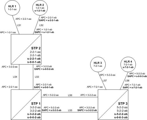
Figure 2-10 shows an example network that is not using the ITU National and International Spare Point Code Support feature.
Note:
For the figures shown in this section, a point code that is prefaced with “s” indicates a spare point code, and a point code that is not prefaced with an “s” indicates a non-spare point code. If a linkset includes an APC (adjacent point code) or SAPC that is prefaced with “s,” the linkset supports traffic to and from ITU-National spare point codes. If the linkset includes an APC or SAPC that is not prefaced with “s,” the linkset supports traffic to and from ITU-National point codes. A linkset that includes both ITU-National and ITU-National spare APC and SAPCs supports both national and national spare traffic. Point codes that are labeled within the STP nodes represent true and secondary EAGLE point codes.Figure 2-10 Example of an Existing Network that is not using the ITU National and International Spare Point Code Support Feature
Stage One
Figure 2-11 shows an example network. The items shown in bold are items that are added during this stage of the migration procedure.
The following steps are performed for each node shown in Figure 2-11, one at a time, as part of this stage of the migration procedure.
- Upgrade each EAGLE shown in Figure 2-11 to the software release that contains the ITU National and International Spare Point Code Support feature by performing the appropriate upgrade procedure.
- Enable the ITU National and International Spare Point Code Support feature on each EAGLE shown in Figure 2-11, by performing the Activating the ITU National and International Spare Point Code Support Feature procedure. Do not turn the feature on at this time.
Note:
Provisioning for the ITU National and International Spare Point Code Support feature can be performed once the feature is enabled. Message processing based on this feature is not performed until the feature is turned on. - Add a new true ITU-National spare point code in the self identification table of each EAGLE by performing the Adding a Point Code to the Self-Identification of the EAGLE procedure at each EAGLE. For example, add these point codes:
- Point code s-3-2-2-ab to STP 1
- Point code s-2-2-1-ab to STP 2
- Point code s-5-2-2-ab to STP 3.
- Add one secondary ITU-National spare point code to each EAGLE by performing the Adding a Secondary Point Code procedure. For example, add these point codes:
- Point code s-0-0-1-ab to STP 2
- Point code s-0-0-2-ab to STP 1
- Point code s-0-0-3-ab to STP 3.
- Add a secondary adjacent ITU-National spare point code (SAPC) to the linksets whose APCs have the “ab” suffix by performing the Configuring an ITU Linkset with a Secondary Adjacent Point Code (SAPC) procedure. For example, add these secondary adjacent point codes:
- SAPC s-0-0-1-ab for linkset LS3 in STP 1
- SAPC s-0-0-2-ab for linkset LS3 in STP 2
- SAPC s-5-2-2-ab for linkset LS5 in STP 1
- SAPC s-3-2-2-ab for linkset LS5 in STP 3
- SAPC s-1-2-1-ab for linkset LS2 in STP 2
- SAPC s-7-2-1-ab for linkset LS8 in STP 3.
This provisioning must be done before National Spare traffic can be routed over the linksets whose APCs have the “ab” suffix using the ITU National and International Spare Point Code Support feature. As a result of this provisioning, linksets LS2, LS3, LS5, and LS8 can support traffic to and from ITU-National spare point codes as well as ITU-National point codes.
- Provision the routes for the ITU-National spare point codes provisioned in step 5 by performing one of these procedures as required.
For example, provision a route to point code s-1-2-1-ab on LS3 at STP 1.
Figure 2-11 Stage One - ITU National and International Spare Point Code Support Feature Provisioned on All Nodes
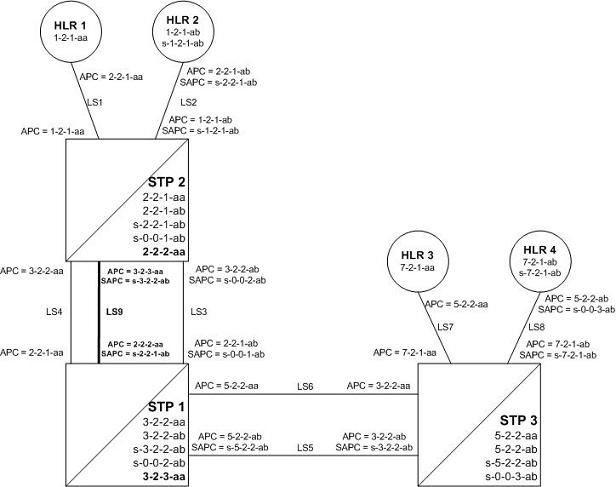
After Stage One has been completed, as indicated in Figure 2-11, linksets LS2, LS3, LS5, and LS8 are capable of supporting traffic to and from both ITU-National and ITU-National spare point codes. Routing decisions, however, are still made using the Duplicate Point Code rules, as the ITU National and International Spare Point Code Support feature has not been turned on.
Stage Two
After stage one is completed for all nodes, the network continues to have the same linksets that it had before this process was started. The same messages are routed over the same linksets, except the new feature is used for routing on select adjacent nodes (STP 1 and STP 2 in this example). This is shown in Figure 2-12 when the feature is turned on for STP 1 and STP 2. Items in bold are added during this stage.
- Turn on MSU processing on STP 1 by turning on the ITU National and International Spare Point Code Support feature. Perform the Activating the ITU National and International Spare Point Code Support Feature procedure on STP 1 to turn the spare point code feature on.
At this point, messages arriving at STP 1 with the DPC 1-2-1-aa that contain the national spare network indicator value 3 ( NI=11binary) are routed using linkset LS3 with the new route provisioned in step 6 of Stage One of this procedure (point code s-1-2-1-ab on LS3 at STP 1).
Messages arriving with DPC 1-2-1-ab that contain the national network indicator value 2 ( NI=10binary) will continue to be routed using linkset LS4.
Since the ITU National and International Spare Point Code Support feature has not been turned on for STP 2 and STP 3, these nodes continue to route traffic according to the Duplicate Point Code feature rules.
- Turn on MSU processing on STP 2 by turning on the ITU National and International Spare Point Code Support feature. Perform the Activating the ITU National and International Spare Point Code Support Feature procedure on STP 2 to turn the spare point code feature on.
At this point, messages arriving at STP 2 with DPC 7-2-1-ab that contain the national spare network indicator value 3 ( NI=11binary) are routed using linkset LS5 with the new route provisioned in step 6 of Stage One of this procedure (point code s-7-2-1-ab on LS5 at STP 2).
Messages arriving with DPC 7-2-1-aa that contain the national network indicator value 2 ( NI=10binary) will continue to be routed using linkset LS6.
- Set the
nisparameter value for linkset LS3 tooffby performing Changing an SS7 Linkset . - Create secondary ITU-National point code 2-2-2-aa on STP 2 and secondary ITU-National point code 3-2-3-aa on STP 1 by performing the Adding a Secondary Point Code procedure on STP 1 and STP 2.
- Create a third linkset, LS9, that contains high-speed signaling links with these APC and SAPC values:
- The APC for linkset LS9 on STP 2 is 3-2-3-aa
- The APC for linkset LS9 on STP 1 is 2-2-2-aa
- The SAPC for linkset LS9 on STP 2 is s-3-2-2-ab
- The SAPC for linkset LS9 on STP 1 is s-2-2-1-ab.
- Adding an SS7 Linkset
- "Configuring an IPGWx Linkset" in Database Administration - IP7 User's Guide.
- "Adding an IPSG M2PA Linkset" in Database Administration - IP7 User's Guide.
- "Adding an IPSG M3UA Linkset" in Database Administration - IP7 User's Guide.
- Provision linkset LS9 to use high-speed signaling links by performing one of these procedures as requried:
- Adding an ATM High-Speed Signaling Link
- "Adding an IPLIMx Signaling Link" procedure in Database Administration - IP7 User's Guide
- "Adding an IPGWx Signaling Link procedure in Database Administration - IP7 User's Guide
- "Adding an IPSG M2PA Signaling Link" in Database Administration - IP7 User's Guide.
- "Adding an IPSG M3UA Signaling Link" in Database Administration - IP7 User's Guide.
- Change the routes on STP 1 to s-1-2-1-ab and 1-2-1-aa so that all National and National Spare traffic uses linkset LS9 by performing the Changing a Route procedure. At this point, incoming National Spare traffic to STP 1 still uses linkset LS3, and incoming National Spare traffic to STP 1 still uses linkset LS4 until the routes on STP 2 are changed so that all National and National Spare traffic uses linkset LS9.
- Provision routes on the adjacent nodes to include the new true and secondary point codes that were added to STP 1 and STP 2. Perform one of these procedures as required.
All traffic (National and National Spare) should now be flowing on linkset LS9.
Figure 2-12 Stage Two - All Traffic Merged onto a Third Linkset
In Figure 2-12, all traffic between STP 1 and STP 2 is routed over linkset LS9, using the national spare network indicator value 3 ( NI=11binary) and the national network indicator value 2 ( NI=10binary) to select the route. Note that linkset LS3 and linkset LS4 are not being used.
Stage Three - Removing Unused Components
The unused components that resulted from the migration need to be removed.
- Perform the Removing a Linkset Containing SS7 Signaling Links procedure to remove the unused linksets. For this example, remove linksets LS3 and LS4.
- Perform the Removing a Destination Point Code procedure to remove the point codes that were the APCs of the unused linksets. For this example, remove point codes 3-2-2-aa and 3-2-2-ab from STP 2, and 2-2-1-aa and 2-2-1-ab from STP 1.
- Perform the Removing a Secondary Point Code procedure to remove the unused secondary point codes. For this example, remove secondary point codes s-0-0-1-ab from STP 2 and s-0-0-2-ab from STP 1.
- Perform the Changing the Self-Identification of the EAGLE procedure to remove any unused true point codes. For this example, remove point code 2-2-1-ab from STP 2.
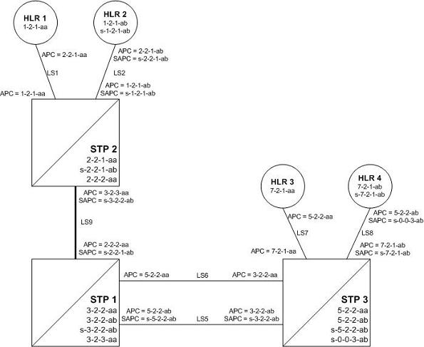
At this point, after all affected linksets have been merged, the situation looks like Figure 2-13. Both National and National Spare traffic between STP 2 and STP 1 are sent over linkset LS9. Traffic between STP 1 and STP 3 continues to route over linkset LS6 for ITU-National point code/group code aa and over linkset LS5 for ITU-National spare point code/group code ab. This is because the ITU National and International Spare Point Code Support feature has been turned on for STP 1 but not for STP 3, so the routes have not been changed between STP 1 and STP 3.
Figure 2-13 Stage Three - All Traffic Merged onto Linkset LS9
2.10 Multiple Point Code Support
Currently, the EAGLE supports six true point codes:
- ANSI point code
- ITU international point code
- ITU international spare point code
- 14-bit ITU national point code
- 14-bit ITU national spare point code
- 24-bit ITU national point code.
Note:
The ITU national point code can be either 14-bit ITU national - spare and non-spare - or 24-bit ITU national. Both 14-bit ITU national and 24-bit national point codes cannot be present in the EAGLE at the same time.
In addition, the EAGLE supports up to 96 capability point codes, each of which can be designated as either ANSI, ITU-I (spare and non-spare), 14-bit ITU-N (spare and non-spare), or 24-bit ITU-N. Each capability point code defined on an EAGLE node can be used for routing messages to that node. For various reasons, customers might need the EAGLE to support more than one true point code in a particular domain.
There are three main reasons driving this feature:
- Some customers desire to collapse multiple existing STP's into one EAGLE. This can present problems in that end offices and other nodes may not be controlled by the carrier making reprovisioning of these network elements difficult. Multiple Point Code (MPC) support is designed to allow the EAGLE to assume more than one point code for SS7 routing. MPC support is different in concept from capability point codes in that provisioning and routing will use secondary point codes as if they were the actual point code of the EAGLE.
- Several customers in the international market want to deploy a single STP pair in multiple national (ITU-N) networks. This may not be possible without the MPC feature, as these operators are often forced to use a unique point code assigned by each national regulator of these target countries.
- Customers may require additional links between two nodes beyond the number of links permitted by the protocol. For example, the maximum number of links between two nodes in an ITU network is 16. The MPC feature can allow for additional linksets between these nodes, increasing the number of links that can be used.
This feature adds the ability to support Secondary Point Codes (SPCs) in addition to the true point codes used by the EAGLE in any of the three domains ANSI, ITU-N (14-bit or 24-bit) and ITU-I. Secondary point codes are used by provisioning and routing as if they are the true point code of the EAGLE. SPCs are supported for any type of link (A, B, C, D, etc.). There is no effect on provisioning capability point codes as a result of this feature.
In addition to the one True Point Code (TPC) already supported for each of the ANSI, ITU-N (14-bit or 24-bit) and ITU-I domains, the EAGLE support a pool of 40 Secondary Point Codes (SPC), each of which may be assigned as either ANSI, ITU-I, 14-bit ITU-N, or 24-bit ITU-N (not to exceed a total of 40 in one EAGLE). SPCs can be used in the same ways that true PCs are used.
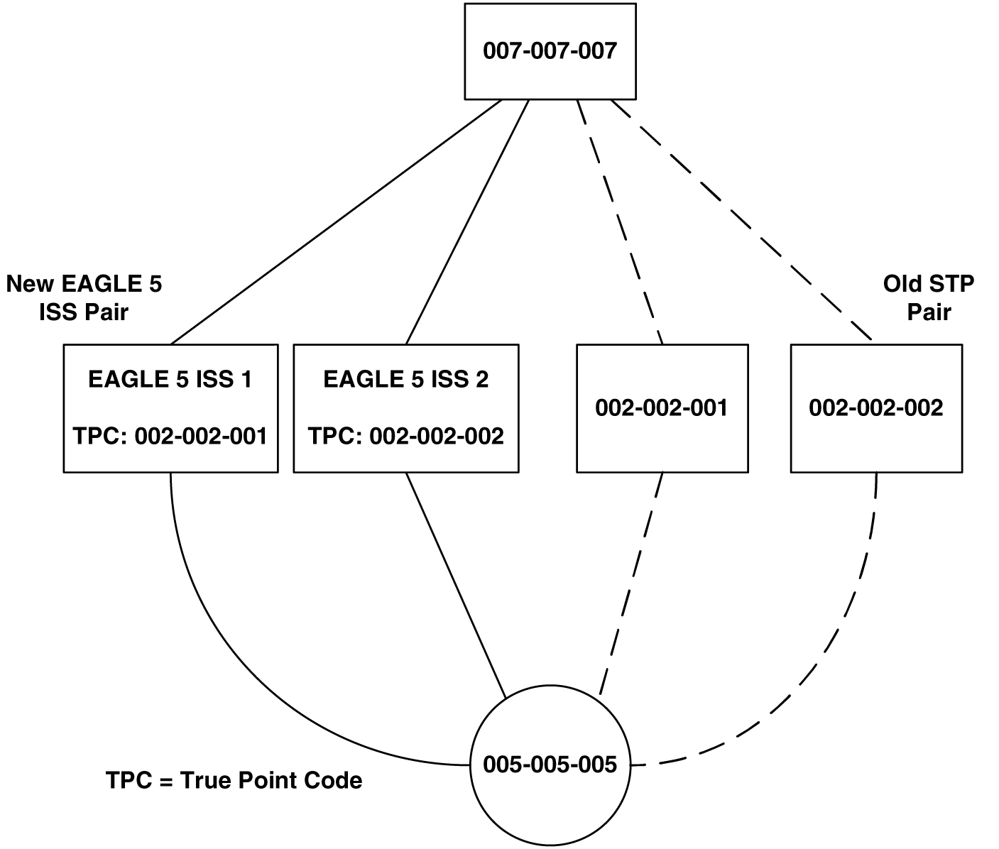
Replacing Two STP Pairs with One Pair
The following example shows how an EAGLE pair can replace two existing STP pairs. In this example, each EAGLE in the pair uses one true point code and one secondary point code.
As shown in Figure 2-14, a new EAGLE first replaces one existing STP pair. In this case, EAGLE's true point code is set to the true point code of the old STP. The adjacent nodes are cut over to the EAGLE pair. The adjacent nodes do not need to be reconfigured.
Figure 2-14 Replacing the First STP Pair
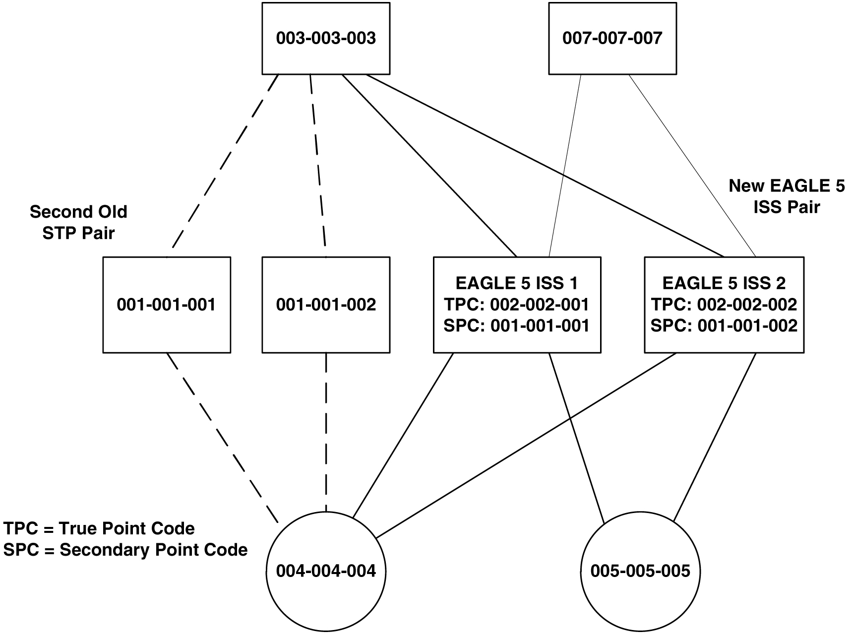
Next, a second STP pair is replaced with the EAGLE pair. As shown in Figure 2-15, an SSP and an STP are being “re-homed” from an old STP pair to a new EAGLE pair. In this example, the STP (003-003-003) is reconfigured with new routes to recognize that it is now connected to EAGLE 1 and EAGLE 2 instead of 001-001-001 and 001-001-002. STP 003-003-003, if not an EAGLE with Multiple Point Codes, may not be able to support more than one linkset to the same point code. See Multiple Linksets between Two Nodes section for a description of this capability. The interconnecting device (STP or SSP) can use either the TPC or SPC as the device requires.
At EAGLE 1, the user would configure the secondary point code 001-001-001, using the ent-spc command. The user would also configure a route to 001-001-002 over the C-linkset. The user would then configure point code 004-004-004 in the EAGLE's database to indicate that this point code uses the secondary point code 001-001-001, instead of the EAGLE's true point code (chg-dstn:dpc=004-004-004:spc=001-001-001. This last step would be repeated for all other adjacent SSPs and SCPs that are re-homed from the old STP Pair to the new EAGLE Pair.
Similarly, at EAGLE 2, the user would configure the secondary point code 001-001-002, and configure a route over the C-link to 001-001-001. The user would also configure point code 004-004-004 in EAGLE 2's database to indicate that this point code uses the secondary point code 001-001-002, instead of the EAGLE's true point code.
When EAGLE 1 receives a message from the SSP destined for 001-001-001, the EAGLE 5 ISS processes the message as if the message was sent to the EAGLE's true point code.
When EAGLE 1 generates a message (for example, network management, link test messages, or GTT messages) that is destined for 004-004-004, EAGLE 1 puts the OPC 001-001-001 in the message. When EAGLE 5 ISS 1 generates a message that is destined for 003-003-003 or 005-005-005, it puts the OPC 002-002-001 in the message. When EAGLE 1 generates GTT and SCMG messages that are destined for non-adjacent point codes, it includes the OPC 002-002-001 in the message.
Figure 2-15 Replacing a Second STP Pair
Multiple Linksets between Two Nodes
With this feature, it is possible to configure multiple linksets between two nodes, if the adjacent node also supports Multiple Point Codes. The EAGLE continues to enforce the rule that each linkset must have a different adjacent point code.
One reason for provisioning multiple linksets between two nodes is to increase the number of links that can be configured between STP pairs. For example, in Figure 2-16, the EAGLE is connected to an STP pair that supports multiple point codes. Without this feature, only 16 ITU links can be configured between the EAGLE and the STP pair (8 links in LS1 and 8 links in LS2). In this example, two linksets are added, increasing the number of links to 32 (8 links in each of LS1, LS2, LS3, and LS4).
Figure 2-16 Multiple Linkset Example
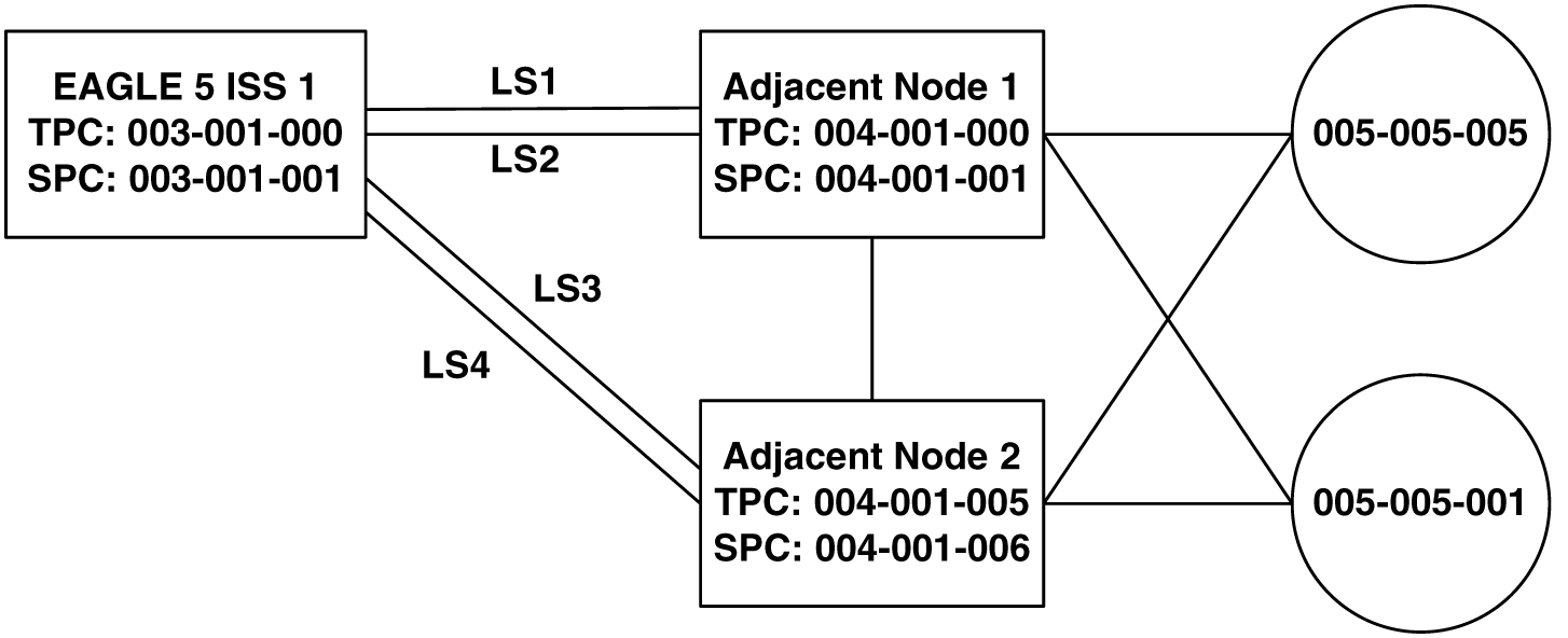
In this example, the adjacent point code (APC) for LS1 is 4-1-0 and the APC for LS2 is 4-1-1. 4-1-1 is assigned an SPC of 3-1-1. So adjacent, Adj Node1 sees LS1 as having an APC of 3-1-0, and LS2 as having an APC of 3-1-1.
To load balance over these 4 linksets, half the destinations that use the STP pair can be assigned LS1 and LS3 as a combined linkset. The other half of the destinations can be assigned LS2 and LS4 as a combined linkset.
The commands to provision EAGLE1 for the network shown in Figure 2-16 are:
chg-sid:pc=3-1-0
ent-spc=3-1-1
ent-dstn:dpc=4-1-0
ent-dstn:dpc=4-1-1:spc=3-1-1
ent-dstn:dpc=4-1-5
ent-dstn:dpc=4-1-6:spc=3-1-1
ent-dstn:dpc=5-5-1
ent-dstn:dpc=5-5-5
ent-ls:lsn=ls1:apc=4-1-0
ent-ls:lsn=ls2:apc=4-1-1
ent-ls: lsn=ls3:apc=4-1-5
ent-ls: lsn=ls4:apc=4-1-6
ent-rte:dpc=4-1-0:lsn=ls1:rc=10
ent-rte:dpc=4-1-1:lsn=ls2:rc=10
ent-rte:dpc=4-1-5:lsn=ls3:rc=10
ent-rte:dpc=4-1-6:lsn=ls4:rc=10
ent-rte:dpc=5-5-1:lsn=ls1:rc=10
ent-rte:dpc=5-5-1:lsn=ls3:rc=10
ent-rte:dpc=5-5-5:lsn=ls2:rc=10
ent-rte:dpc=5-5-5:lsn=ls4:rc=10
Local Number Portability
Note:
Local number portability supports only ANSI point codes.The EAGLE allows only the true point code to be entered into the mated application table. Also, the EAGLE continues to allow the user to enter translations to the true point code. However, the EAGLE does not allow the user to enter translation to a secondary point code.
If a node sends a rt-on-gt query, the node should set the query's DPC to the EAGLE's capability point code. If a node sends an rt-on-ssn query, the node should set the query's DPC to the true point code or secondary point code used by that node. If the node has a secondary point code, then the query’s DPC is set to the secondary point code. If the node does not have a secondary point code, then the query’s DPC is set to the true point code.
rt-on-gt Queries from a Node That Uses Secondary Point Codes
Nodes that send rt-on-gt queries should use the capability point code, regardless of whether these nodes use a true or a secondary point code.
- The node sends a query containing this information:
- The DPC is the capability point code of the EAGLE's LNP subsystem.
- The routing indicator in the called party address is GT.
- The point code in the calling party address is the node's point code.
- The result of the translation contains this information:
- The DPC is the EAGLE’s true point code.
- The routing indicator in the called party address is SSN.
- The subsystem number in the calling party address is the LNP subsystem number.
- The LNP subsystem sends a reply with this information:
- The DPC is the calling party address’ point code.
- The OPC is the EAGLE’s secondary point code.
- The routing indicator in the called party address is SSN.
- The DPC is the node's point code.
- The OPC is the EAGLE’s secondary point code.
- The concerned point code is the EAGLE's capability point code.
This TFP causes the node to divert traffic to the mate.
If a node sends an rt-on-gt query to either the EAGLE's true point code or a secondary point code, the EAGLE cannot divert traffic to the mate. In this case, the EAGLE does not send a TFP concerning the secondary point code or the true point code, so the node will not divert traffic to the mate.
rt-on-ssn queries from a Node That Uses Secondary Point Codes
It is possible that nodes using a secondary point code will send rt-on-ssn queries. In this case, these nodes should send the queries to the secondary point code. The EAGLE will accept rt-on-ssn queries from these nodes if the DPC is the true point code or a secondary point code. However, SCCP management will not work correctly if the rt-on-ssn queries do not use the true point code or a secondary point code associated with the sending node.
- Nodes send queries to the EAGLE with this information:
- The DPC is the EAGLE’s secondary point code.
- The routing indicator in the called party address is SSN.
- The subsystem number in the called party address is the LNP subsystem number.
- The subsystem number is the LNP subsystem number.
- The point code in the calling party address is the node's point code.
- The LNP subsystem sends a reply with this information:
- The DPC is the point code in the calling party address.
- The OPC is the secondary point code.
- The routing indicator in the called party address is SSN.
- The point code in the calling party address is the secondary point code.
- The DPC is the node's point code.
- The OPC is the secondary point code.
- The affected point code is the secondary point code.
- The affected subsystem number is the LNP subsystem number.
Limitations
The same adjacent point code cannot be used for two different links.
Local EAGLE subsystems (for example, LNP) must use the True Point Code.
2.11 Adding a Secondary Point Code
This procedure is used to add a secondary point code to the database using the ent-spc command.
The ent-spc command uses only one parameter: spc/spca/spci/spcn/spcn24 – the secondary point code.
Note:
See Point Code Formats for a definition of the point code types that are used on the EAGLE and for a definition of the different formats that can be used for ITU national point codes.The secondary point code must be a full point code. Cluster and network routing point codes cannot be specified as a secondary point code.
The Multiple Point Code Support feature must be on to configure secondary point codes in the database. This can be verified with the entry MPC = on in the rtrv-feat command output. If the Multiple Point Code Support feature is not turned on, enter the chg-feat:mpc=on command.
Note:
Once the Multiple Point Code Support feature is turned on with thechg-feat command, it cannot be turned off.
The Multiple Point Code Support feature must be purchased before you turn this feature on with the chg-feat command. If you are not sure if you have purchased the Multiple Point Code Support feature, contact your Oracle Sales Representative or Account Representative.
The database can contain up to 40 secondary point codes.
The secondary point code cannot be defined in the database as the true point code of the EAGLE, a capability point code, a destination point code, or an alias point code. The true point code and capability point codes are shown in the rtrv-sid command output. The destination point codes and alias point codes are shown in the rtrv-dstn command output.
The secondary point code cannot be shown in the rtrv-pct output as an EPC (emulated point code) value.
For the examples in this procedure, these secondary point codes are being added to the database:
ANSI secondary point code = 010-100-010
ITU secondary international point code = 4-100-1
14-bit ITU secondary national point code = 14-15-12-1
The format of the 14-bit ITU national point codes used in these examples is 4-4-4-2.
Canceling the RTRV-DSTN Command
Because the rtrv-dstn command used in this procedure can output information for a long period of time, the rtrv-dstn commands can be canceled and the output to the terminal stopped. There are three ways that the rtrv-dstn command can be canceled:
- Press the
F9function key on the keyboard at the terminal where thertrv-dstncommand was entered. - Enter the
canc-cmdwithout thetrmparameter at the terminal where thertrv-dstncommand was entered. - Enter the
canc-cmd:trm=<xx>, where<xx>is the terminal where thertrv-dstncommand was entered, from another terminal other than the terminal where thertrv-dstncommand was entered. To enter thecanc-cmd:trm=<xx>command, the terminal must allow Security Administration commands to be entered from it and the user must be allowed to enter Security Administration commands. The terminal’s permissions can be verified with thertrv-secu-trmcommand. The user’s permissions can be verified with thertrv-userorrtrv-secu-usercommands.
For more information about the canc-cmd command, refer to Commands User's Guide.
Figure 2-17 Adding a Secondary Point Code
2.12 Removing a Secondary Point Code
This procedure is used to remove a secondary point code from the database using the dlt-spc command.
The dlt-spc command uses only one parameter: spc/spca/spci/spcn/spcn24 – the secondary point code.
Note:
See Point Code Formats for a definition of the point code types that are used on the EAGLE and for a definition of the different formats that can be used for ITU national point codes.The secondary point code being removed from the database must be in the database, but cannot be referenced by any destination point codes or by any linksets. Entering the rtrv-dstn command with either the spca, spci, spcn, or spcn24, depending on the point code type of the secondary point code being removed from the database, shows the destination point codes that are referencing the secondary point code being removed from the database.
Entering the rtrv-ls command with either the spca, spci, spcn, or spcn24, depending on the point code type of the secondary point code being removed from the database, shows the linksets that are referencing the secondary point code being removed from the database.
For the example in this procedure, secondary point code 010-100-010 is being removed from the database.
Canceling the RTRV-DSTN Command
Because the rtrv-dstn command used in this procedure can output information for a long period of time, the rtrv-dstn commands can be canceled and the output to the terminal stopped. There are three ways that the rtrv-dstn command can be canceled:
- Press the
F9function key on the keyboard at the terminal where thertrv-dstncommand was entered. - Enter the
canc-cmdwithout thetrmparameter at the terminal where thertrv-dstncommand was entered. - Enter the
canc-cmd:trm=<xx>, where<xx>is the terminal where thertrv-dstncommand was entered, from another terminal other than the terminal where thertrv-dstncommand was entered. To enter thecanc-cmd:trm=<xx>command, the terminal must allow Security Administration commands to be entered from it and the user must be allowed to enter Security Administration commands. The terminal’s permissions can be verified with thertrv-secu-trmcommand. The user’s permissions can be verified with thertrv-userorrtrv-secu-usercommands.
For more information about the canc-cmd command, refer to Commands User's Guide.
Figure 2-18 Removing a Secondary Point Code
2.13 Adding a Point Code to the Self-Identification of the EAGLE
This procedure is used to add a true point code to the self-identification of the EAGLE using the ent-sid command. Adding the point code using this procedure instead of the Changing the Self-Identification of the EAGLE procedure does not require the EAGLE to be re-initialized after the point code is added.
However, if you wish to add a capability point code, change an existing true point code, change the CLLI value, or the pctype parameter value in the self-identification, the Changing the Self-Identification of the EAGLE procedure must be used.
The ent-sid command uses these parameters:
:pc/pca – ANSI point code
:pci – ITU-I or ITU-I spare point code
:pcn – 14-bit ITU-N or 14-bit ITU-N spare point code
:pcn24 – 24-bit ITU-N point code
Note:
See Point Code Formats for a definition of the point code types that are used on the EAGLE and for a definition of the different formats that can be used for ITU national point codes.The network type of the point code being added in this procedure cannot be the same as the network type of any point codes shown in PCA, PCI, PCN, or PCN24 columns in the rtrv-sid output. For example, if an ANSI point code is shown in the rtrv-sid output (a point code in the PCA column), then the pc/pca parameter cannot be specified in this procedure.
However, the self-identification can contain both spare and non-spare point codes for the PCI and PCN values. If the rtrv-sid output contains an ITU-I point code, but does not contain an ITU-I spare point code, the pci parameter can be specified with an ITU-I spare point code value. If spare and non-spare point codes are shown for the PCI value, then the pci parameter cannot be specified in this procedure. This is also true for 14-bit ITU-N and 14-bit ITU-N spare point codes.
The point code of the EAGLE cannot match the capability point codes of the EAGLE or any destination point codes or alias point codes. Capability point code are shown in the rtrv-sid output. Destination point codes and alias point codes are shown in the rtrv-dstn output.
The point code of the EAGLE must be a full point code and cannot be a cluster point code. The point code containing all zeros cannot be used as a value for these parameters.
The point code value for the pcn parameter (either 14-bit ITU-N or 14-bit ITU-N spare point code) must match the format defined by the NPCFMTI parameter of the rtrv-stpopts output. If group codes are shown for the 14-bit ITU-N point codes in the rtrv-sid output, then a group code must be specified with the pcn parameter value. The group code must match the group codes shown in the rtrv-sid or rtrv-spc outputs.
Figure 2-19 Adding a Point Code to the Self-Identification of the EAGLE
2.14 Changing the Self-Identification of the EAGLE
This procedure is used to change the self-identification of the
EAGLE using the chg-sid command. The
self-identification of the EAGLE is a
set of point codes made up of a true point code (PC) and a capability point code (CPC)
for each network type to which the EAGLE is connected. A capability point code identifies a group of nodes that
have similar capabilities, for example, global title translation.
Caution:
Use this procedure only during periods of low traffic. If the EAGLE’s point code, defined by thepc/pca/pci/pcn/pcn24 parameter, is changed with
the procedure, the EAGLE must be reinitialized with the init-sys command. The init-sys command
reboots the entire EAGLE and reloads all cards with the updated self-identification
information.
Therstrdev value of thechg-stpopts
command can be used to turn on the Persistent Device States (PDS) feature. If
PDS is on, the current device
states for cards, signaling links, and terminals are restored after the init-sys command has
executed. Refer to the chg-stpopts command description in Commands User's
Guide for more information about PDS.
Note:
If thePCA, PCI, PCN, or PCN24 fields in the rtrv-sid output do not contain any values, and you only wish to add these values, it is recommended that the “Adding a Point Code to the Self-Identification of the EAGLE” procedure procedure be used to add these values instead of using this procedure as the “Adding a Point Code to the Self-Identification of the EAGLE” procedure does not require the EAGLE to be re-initialized after the point code value is added.
The chg-sid command uses these parameters:
:pc/pca/pci/pcn/pcn24 – The point code used to uniquely identify the EAGLE or, with the value none, the point code is defined by the pc/pca/pcn24 parameter is removed from the database. Removing the pci or pcn value should be done by using the npci or npcn parameters.
:cpc/cpca/cpci/cpcn/cpcn24 – The point code used to identify a group of functionally related nodes in the signaling network to which the EAGLE belongs. This point code is called the capability point code.
:ncpc/ncpca/ncpci/ncpcn/ncpcn24 – The new capability point code that replaces an existing capability point code in the database or, with the value none, removes an existing capability point code from the database.
:npci/npcn – The new ITU-I (npci) or 14-bit ITU-N (npcn) point code used to uniquely
identify the EAGLE that replaces an
existing pci or
pcn parameter
value, with the value none, removes an existing pci or pcn parameter value from the
database. The npci/npcn parameter values cannot be equal to any cpc or pc parameter values. The pci parameter must be
specified if the npci parameter is specified. The pcn parameter must be specified if
the npcn
parameter is specified. The new ITU-I or 14-bit ITU-N point code values (npci/npcn) must be the same type as
the pci/pcn
parameter value. For example, if the pci value is a non-spare point code,
the npci value
must be a non-spare point code. If the pci value is a spare point code, the
npci value
must be a spare point code.
Note:
See Point Code Formats for a definition of the point code types that are used on the EAGLE and for a definition of the different formats that can be used for ITU national point codes.:clli – The Common Language Location Identifier assigned to the EAGLE
:pctype – Point code type, either ansi or other.
:cpctype – the type of capability point code: STP, LNP, INP, EIR, GPORT, GFLEX, MNP, VFLEX, ATINPQ, AIQ.
The self-identification of the EAGLE can consist of an ANSI point code, an ITU international non-spare point code, an ITU international spare point code, a 14-bit ITU national non-spare point code, a 14-bit ITU national spare point code, or a 24-bit ITU national point code, or combinations of these types of point codes. The self-identification of the EAGLE cannot have both a 14-bit ITU-N point code (spare or non-spare) and a 24-bit ITU-N point code.
The self-identification of the EAGLE must contain point codes whose formats match the network the EAGLE is connected to. For example, if the EAGLE is connected to an ANSI network, the self-identification of the EAGLE must contain an ANSI point code. If the EAGLE is connected to an ITU international network, the self-identification of the EAGLE must contain an ITU international point code. If the EAGLE is connected to an ITU national network, the self-identification of the EAGLE must contain either a 14-bit or a 24-bit ITU national point code.
The self-identification of the EAGLE can contain capability point codes. A capability point code is used by the SS7 protocol to identify a group of functionally related nodes in the signaling network. The self-identification of the EAGLE can contain up to 96 capability point codes which can be all one point code network type, or a mixture of all three point code network types.
The EAGLE can contain an ANSI capability point code, an ITU national capability point code (spare or non-spare), and either a 14-bit (spare or non-spare) or a 24-bit ITU-N capability point code.
Note:
The self-identification of the EAGLE cannot contain private point codes, and private point codes cannot be assigned as capability point codes.ITU international and 14-bit ITU national spare point codes can be specified only if the ITU National and International Spare Point Code Support feature is enabled. The status of this feature can be verified by entering the rtrv-ctrl-feat command. If the ITU National and International Spare Point Code Support feature is not enabled, perform the Activating the ITU National and International Spare Point Code Support Feature to enable the ITU National and International Spare Point Code Support feature.
The self-identification of the EAGLE can also contain a CLLI, the common language location identifier of the EAGLE.
The CLLI of the EAGLE cannot match the CLLI of any destination point code. Use the rtrv-dstn command to verify the CLLIs of the destination point codes in the database.
If the CLLI of the Eagle is changed and the SEAS over IP feature is enabled and turned on, the CCSMR configuration must be updated with the new CLLI. Perform the procedures in the "SEAS over IP Configuration Procedures" chapter in the Database Administration - System Management User's Guide to update the CCSMR configuration.
If the CLLI of the EAGLE is to be changed, and the Eagle Support for Integrated Sentinel (E5IS) feature is on, the EISCOPY option must be off before the chg-sid command is executed. The value of the EISCOPY option can be verified with the rtrv-eisopts command. After the chg-sid command is executed, the EISCOPY option must be changed back to on.
Note:
For the complete list of cards supported by EAGLE Release 47.0, see Hardware Reference Guide.cpctype parameter with the capability point code parameters, cpc/cpca/cpci/cpcn/cpcn24, or the new capability point code parameters, ncpc/ncpca/ncpci/ncpcn/ncpcn24. The EAGLE supports these types of capability point codes.- STP capability point codes are specified with the
cpctype=stpparameter. STP capability point codes can be any point code type. STP capability point codes can be specified regardless of which features are enabled or turned on. - LNP capability point codes are specified with the
cpctype=lnpparameter. LNP capability point codes can be only ANSI point codes, specified with either thecpc,cpca,ncpc, orncpcaparameters. The LNP feature must be enabled to specify thecpctype=lnpparameter. This can be verified with thertrv-ctrl-featcommand. If the LNP feature is enabled, the entryLNP TNsis shown in thertrv-ctrl-featcommand output with a quantity greater than zero.If any of these capability point codes are shown in the
rtrv-sidoutput: INP, EIR, G-Port, G-Flex, MNP, V-Flex, ATINPQ; then LNP capability point codes cannot be provisioned. If any of these features are enabled, and turned on if required: INP, ANSI-41 INP Query, EIR, G-Port, A-Port, G-Flex, IS41 GSM Migration, V-Flex, ATINP; then LNP capability point codes cannot be provisioned. If the LNP feature is not enabled, perform the procedures in ELAP Administration and LNP Feature Activation User's Guide to enable the LNP feature. - INP capability point codes are specified with the
cpctype=inpparameter. INP capability point codes can be either an ITU-I, 14-bit ITU-N, or 24-bit ITU-N point code, specified with either thecpci,cpcn,cpcn24,ncpci,ncpcn, orncpcn24parameters. The INP or ANSI-41 INP Query feature must be enabled and turned on to specify thecpctype=inpparameter. Enter thertrv-ctrl-featcommand to verify whether or not the INP or ANSI-41 INP Query feature is enabled and turned on.If LNP capability point codes are shown in the
rtrv-sidoutput, or the LNP feature is enabled, INP capability point codes cannot be provisioned. If either the INP or ANSI-41 INP Query feature is not enabled or turned on, perform the procedures in the INP/AINPQ User's Guide to enable and turn on the INP or ANSI-41 INP Query feature. - EIR capability point codes are specified with the
cpctype=eirparameter. EIR capability point codes can be either an ITU-I, 14-bit ITU-N, or 24-bit ITU-N point code, specified with either thecpci,cpcn,cpcn24,ncpci,ncpcn, orncpcn24parameters. The EIR feature must be enabled and turned on to specify thecpctype=eirparameter. Enter thertrv-ctrl-featcommand to verify whether or not the EIR feature is enabled and turned on.If LNP capability point codes are shown in the
rtrv-sidoutput, or the LNP feature is enabled, EIR capability point codes cannot be provisioned. If the EIR feature is not enabled or turned on, perform the procedures in EIR User's Guide to enable and turn on the EIR feature. - G-Flex capability point codes are specified with the
cpctype=gflexparameter. G-Flex capability point codes can be any point code type. The G-Flex feature must be enabled and turned on to specify thecpctype=gflexparameter. Enter thertrv-ctrl-featcommand to verify whether or not the G-Flex feature is enabled and turned on. If LNP capability point codes are shown in thertrv-sidoutput, or if the LNP feature is enabled, G-Flex capability point codes cannot be provisioned. If the G-Flex feature is not enabled or turned on, perform the procedures in G-Flex User's Guide to enable and turn the G-Flex feature on. - G-Port capability point codes are specified with the
cpctype=gportparameter. G-Port capability point codes can be any point code type. The G-Port feature must be enabled to specify thecpctype=gportparameter. Enter thertrv-ctrl-featcommand to verify whether or not the G-Port feature is enabled. If LNP or MNP capability point codes are shown in thertrv-sidoutput, or the LNP, A-Port, or IS41 GSM Migration features are enabled, G-Port capability point codes cannot be provisioned. If the G-Port feature is not enabled, perform the procedures in G-Port User's Guide to enable the G-Port feature. - MNP capability point codes are specified with the
cpctype=mnpparameter. MNP capability point codes can be any point code type. The A-Port feature or IS41 GSM Migration feature must be enabled to specify thecpctype=mnpparameter. Enter thertrv-ctrl-featcommand to verify whether or not the A-Port feature or IS41 GSM Migration feature is enabled. If LNP or G-Port capability point codes are shown in thertrv-sidoutput, or the LNP or G-Port features are enabled, MNP capability point codes cannot be provisioned. If the A-Port feature is not enabled, perform the procedures in A-Port User's Guide to enable the A-Port feature. If the IS41 GSM Migration feature is not enabled, perform the procedures in IS41 GSM Migration User's Guide to enable the IS41 GSM Migration feature. - V-Flex capability point codes are specified with the
cpctype=vflexparameter. V-Flex capability point codes can be any point code type. The V-Flex feature must be enabled and turned on to specify thecpctype=vflexparameter. Enter thertrv-ctrl-featcommand to verify whether or not the V-Flex feature enabled and turned on. If LNP capability point codes are shown in thertrv-sidoutput, or the LNP feature is enabled, V-Flex capability point codes cannot be provisioned. If the V-Flex feature is not enabled or turned on, perform the procedures in V-Flex User's Guide to enable and turn on the V-Flex feature. - ATINPQ capability point codes are specified with the
cpctype=atinpqparameter. ATINPQ capability point codes can be either an ANSI, ITU-I, or 14-bit ITU-N point code, specified with either thecpc/cpca,cpci,cpcn,ncpc/ncpca,ncpci, orncpcnparameters.The ATINP feature must be enabled to specify the
cpctype=atinpqparameter. Enter thertrv-ctrl-featcommand to verify whether or not the ATINP feature is enabled. If LNP capability point codes are shown in thertrv-sidoutput, or the LNP feature is enabled, ATINPQ capability point codes cannot be provisioned. If the ATINP feature is not enabled, perform the procedures in ATINP User's Guide to enable the ATINP feature. - AIQ capability point codes are specified with the
cpctype=aiqparameter. AIQ capability point codes can be either an ANSI, ITU-I, or 14-bit ITU-N point code, specified with either thecpc/cpca,cpci,cpcn,ncpc/ncpca,ncpci, orncpcnparameters.The ANSI41 AIQ feature must be enabled to specify the
cpctype=aiqparameter. Enter thertrv-ctrl-featcommand to verify whether or not the ANSI41 AIQ feature is enabled. AIQ capability point codes can be specified regardless of which features, other than the ANSI41 AIQ feature, are enabled or turned on. If the ANSI41 AIQ feature is not enabled, perform the procedures in the Analyzed Information Features User's guide to enable the ANSI41 AIQ feature.
The pctype parameter of the chg-sid command determines the format of point codes (but not the ITU international or ITU national point codes) that can be used on the EAGLE, ansi and other. The value ansi means the EAGLE supports point codes that meet the ANSI standard. The value other means that the EAGLE supports point codes that do not meet the ANSI standard. The pctype parameter does not apply to ITU international or ITU national point codes. See the “ANSI Point Codes” in the Point Code Formats section for more information about ANSI point codes.
This procedure causes a change in the routing information for this node. Make sure that all other nodes that route messages to this node are notified of these changes.
The point code of the EAGLE cannot match the capability point codes of the EAGLE. The point code of the EAGLE and the capability point codes of the EAGLE are shown in 1.
The point code and capability point codes of the EAGLE cannot match any destination point codes. Use the rtrv-dstn command to display the destination point codes in the database.
The point code and capability point codes of the EAGLE cannot be defined as a destination point code of a route. Use the rtrv-rte command to display the destination point codes of the routes in the database.
The point code and capability point codes of the EAGLE cannot match any emulated point code (EPC) values that are shown in the rtrv-pct output
The point code of the EAGLE or the capability point codes, specified by the pc/pca/pci/pcn/pcn24, cpc/cpca/cpci/cpcn/cpcn24 or ncpc/ncpca/ncpci/ncpcn/ncpcn24 parameters, must be a full point code and cannot be a cluster point code. A point code containing all zeros cannot be used as a value for ANSI (pc/pca, cpc/cpca, ncpc/ncpca) and ITU-I (pci, cpci, ncpci) parameters. A point code containing all zeros can be used as a value for 14-bit ITU-N (pcn, cpcn, ncpcn) and 24-bit ITU-N (pcn24, cpcn24, ncpcn24) parameters.
If either the cpctype parameter or the capability point code parameter (cpc/cpca/cpci/cpcn/cpcn24) are specified, the other parameter must be specified.
If the new capability point code parameter (ncpc/ncpca/ncpci/ncpcn/ncpcn24) is specified, the capability point code parameter (cpc/cpca/cpci/cpcn/cpcn24) and the cpctype parameters must be specified.
Only one of the new capability point code parameters (ncpc/ncpca/ncpci/ncpcn/npcn24) can be specified with the chg-sid command.
The new capability point code (ncpc/ncpca/ncpci/ncpcn/npcn24) must be of the same point code type as the capability point code (cpc/cpca/cpci/cpcn/cpcn24) specified in the command. For example, if an ITU international capability point code (cpci) is being replaced, then only the ncpci parameter can be specified.
The point code of the EAGLE cannot be changed if it is referenced in the mated application table. Enter the rtrv-map command to verify if the EAGLE’s point code is being referenced in the mated application table. The EAGLE’s point code would be shown in the PCA, PCI, PCN, PCN24, MPCA, MPCI, MPCN, or MPCN24 fields of the rtrv-map command output. If the EAGLE’s point code is referenced by the mated application table, perform the Removing a Mated Application procedure in Database Administration - GTT User's Guide, and remove the mated applications that reference the EAGLE’s point code.
The destination point codes and alias point codes are shown in the DPCA, DPCI, DPCN, DPCN24, ALIASA, ALIASI, ALIASN, and ALIASN24 fields in the rtrv-dstn command output. Secondary point codes are shown in the SPCA, SPCI, SPCN, and SPCN24 fields in the rtrv-spc command output. The EAGLE’s point code and capability point codes are displayed in the PCA, PCI, PCN, PCN24, CPCA, CPCI, CPCN, and CPCN24 fields in the rtrv-sid command output. The EAGLE’s true point code and capability point codes cannot be shown in either the rtrv-dstn or rtrv-spc command outputs.
To assign group codes to a 14-bit ITU-N point code, the ITU duplicate point code and multiple point code support features must be on. If the ITU National Duplicate Point Code feature is on, the entry ITUDUPPC = on is shown in the rtrv-feat command output. If the multiple point code support feature is on, the entry MPC = on is shown in the rtrv-feat command output. For more information on using group codes with 14-bit ITU-N point codes, see the ITU National Duplicate Point Codes section.
Note:
Once the ITU duplicate point code and multiple point code support features are turned on with thechg-feat command, they cannot be turned off.
The ITU duplicate point code and multiple point code support features must be purchased before you turn this feature on with the chg-feat command. If you are not sure if you have purchased the ITU duplicate point code and multiple point code support features, contact your Oracle Sales Representative or Account Representative.
If you wish to specify the pcn24 parameter with the chg-sid command and the rtrv-sid output shows the PCN field, the 14-bit ITU-N point code value, shown in the PCN field must be removed with the npcn=none parameter before the pcn24 parameter value can be specified by the chg-sid command. If the PCN field contains both spare and non-spare point code values, both the spare and non-spare 14-bit ITU-N point code values must be removed before the pcn24 parameter can be specified. If no value is shown in the PCN field, specifying the npcn=none parameter is not necessary.
If you wish to specify the pcn parameter with the chg-sid command and the rtrv-sid output shows the PCN24 field, the 24-bit ITU-N point code value, shown in the PCN24 field must be removed with the pcn24=none parameter before the pcn parameter value can be specified by the chg-sid command. If no value is shown in the PCN24 field, specifying the pcn24=none parameter is not necessary.
When the EAGLE is initially installed, the self-identification of the EAGLE must be configured before any destination point codes can be configured in the database.
For the examples in this procedure, the self-identification of the EAGLE is being changed to these values:
ANSI point code = 100-100-100
ITU international point code = 3-75-7
14-bit ITU national point code = 7-9-8-1
LNP capability point code = 006-006-006
The format of the 14-bit ITU national point codes used in these examples is 4-4-4-2.
Canceling the RTRV-DSTN, RTRV-MAP, and RTRV-RTE Commands
Because the rtrv-dstn, rtrv-map, and rtrv-rte commands used in this procedure can output information for a long period of time, the rtrv-dstn, rtrv-map, and rtrv-rte commands can be canceled and the output to the terminal stopped. There are three ways that the rtrv-dstn, rtrv-map, and rtrv-rte commands can be canceled:
-
Press the
F9function key on the keyboard at the terminal where thertrv-dstn,rtrv-map, orrtrv-rtecommand was entered. -
Enter the
canc-cmdwithout thetrmparameter at the terminal where thertrv-dstn,rtrv-map, orrtrv-rtecommand was entered. -
Enter the
canc-cmd:trm=<xx>, where<xx>is the terminal where thertrv-dstn,rtrv-map, orrtrv-rtecommand was entered, from another terminal other than the terminal where thertrv-dstn,rtrv-map, andrtrv-rtecommands were entered. To enter thecanc-cmd:trm=<xx>command, the terminal must allow Security Administration commands to be entered from it and the user must be allowed to enter Security Administration commands. The terminal’s permissions can be verified with thertrv-secu-trmcommand. The user’s permissions can be verified with thertrv-userorrtrv-secu-usercommands.
For more information about the canc-cmd command, refer to Commands User's Guide.
Figure 2-20 Changing the Self-Identification of the EAGLE
2.15 Cluster Routing and Management Diversity (CRMD)
The Cluster Routing and Management Diversity feature eliminates the need for a full point code entry in the routing table to route to every signaling point in every network. The Cluster Routing and Management Diversity feature allows the EAGLE to configure one routeset to a entire cluster of destinations. This feature also allows the EAGLE to manage and switch traffic to more end nodes.
A cluster is defined as a group of signaling points whose point codes have identical values for the network and cluster fields of the point codes. A cluster entry in the routing table is shown with an asterisk (*) in the member field of the point code, for example, 111-011-*. With this feature, ANSI destination point codes can be specified as either a full point code, for example, 123-043-045, or as a cluster of signaling point codes, for example, 111-011-*.
Note:
Cluster entries can only be provisioned as ANSI destination point codes. Cluster entries cannot be provisioned for ITU international or ITU national destination point codes. The ANSI alias point code for an ITU international or ITU national destination point code must be a full point code.The Cluster Routing and Management Diversity feature allows provisioning of clusters, as well as of full point codes that belong to the same cluster as destination point codes (Figure 2-21). The point codes 111-011-*, 111-011-005 and 111-011-045 entries can be provisioned. In Figure 2-21, the cluster destination point code 111-011-* represents all the point codes of the cluster except for point codes 111-011-005 and 111-011-045. Cluster entries in the destination point code table can also be used as a DPC for a route. A group of such routes with varying relative cost forms a routeset to a cluster, just like a routeset to a full point code.
Figure 2-21 Cluster Routing and Management Diversity
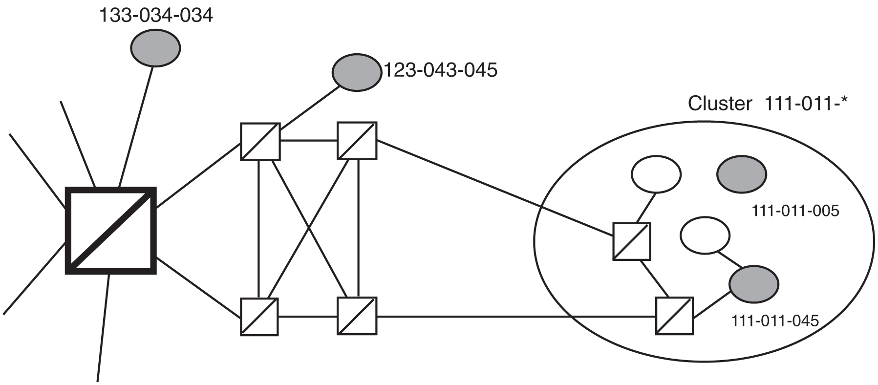
Exception Lists (X-lists)
An exception list for a cluster is a list of point codes in a cluster whose routes are more restricted than other routes to that cluster. The term “more restricted” is used when comparing the route status of a cluster member to the route status of the cluster. A PROHIBITED status is more restrictive than a RESTRICTED status, and a RESTRICTED status is more restrictive than an ALLOWED status.
This list contains point codes that are not assigned to any individual routeset, and the only routeset to that node is through a cluster routeset. The exception list is a dynamic list that changes when the status of the cluster routesets changes.
The EAGLE allows users to specify whether exception list entries need to be created on a per cluster basis. For each cluster, the user can specify an exception list exclusion indicator (ELEI) when configuring the cluster point code with the ent-dstn command. When the ELEI is yes, the EAGLE does not create exception list entries or remove any existing exception list entries for the given cluster. When the ELEI is no, the EAGLE creates and removes exception list entries. When the ELEI is no, it is not guaranteed that there will be space available to create each and every possible exception list entry for provisioned cluster entries. All such exception list entries must compete for available exception list space.
Exception list entries are stored as an extension of the Destination Point Code table. The Destination Point Code table can contain a maximum number of entries, as shown in Table 2-5. The EAGLE allows the user to specify the number of entries reserved for the exception list. Table 2-5 also shows the number of entries that can be reserved for the exception list and the number of entries that are reserved for configured destinations (the full, cluster point codes, and network routing point codes).
Table 2-5 Maximum Point Code Quantities
| Feature Status | Maximum DPC Quantity | Number of Entries Reserved for the Exception List | Maximum Number of Full, Cluster, and Network Routing Point Codes |
|---|---|---|---|
| The 5000 Routes feature is off and 6000, 7000, 8000, or 10,000 routesets are not enabled | 2500 | 500 - 2000 | 2500 minus the number of entries reserved for the exception list. |
| The 5000 Routes feature is on and 6000, 7000, 8000, or 10,000 routesets are not enabled | 5500 | 500 - 5000 | 5500 minus the number of entries reserved for the exception list. |
| 6000 routesets are enabled | 6500 | 500 - 6000 | 6500 minus the number of entries reserved for the exception list. |
| 7000 routesets are enabled | 7500 | 500 - 6000 | 7500 minus the number of entries reserved for the exception list. |
| 8000 routesets are enabled | 8500 | 500 - 6000 | 8500 minus the number of entries reserved for the exception list. |
| 10,000 routesets are enabled | 10500 | 500 - 10000 | 10500 minus the number of entries reserved for the exception list. |
The outputs of the ent-dstn, dlt-dstn, chg-dstn, and rtrv-dstn commands display this destination point code usage information.
- The number of configured full point codes
- The number of configured cluster point codes
- The number of configured network routing point codes
- The sum of configured destinations (full, network routing, and cluster point codes)
- The number of DPCs the EAGLE may contain (full, network routing, and cluster point codes). This number is the value of the
chg-stpoptscommand’smtpdpcqparameter. Themtpdpcqparameter value is not always the maximum number of entries minus the number reserved for the exception list. This calculation determines the maximum number of DPCs the EAGLE may contain. Themtpdpcqparameter value of thechg-stpoptscommand determines the actual number of DPCs the EAGLE can have, and can be set to an amount less than the maximum. - The number of entries reserved for exception list. This number is the value of the
chg-stpoptscommand’smtpxlqparameter. - The maximum number of alias point codes that can be in the EAGLE. The EAGLE can contain the quantities of alias point codes shown in Table 2-6 depending the features that are enabled or turned on.
Table 2-6 Maximum Alias Point Code Quantities
Feature Status Maximum Alias Point Code Quantity The 5000 Routes feature is off and 6000, 7000, 8000, or 10,000 routesets are not enabled 12000 The 5000 Routes feature is on and 6000, 7000, 8000, or 10,000 routesets are not enabled 12000 6000 routesets are enabled 12000 7000 routesets are enabled 8000 8000 routesets are enabled 8000 10,000 routesets are enabled 10000 - The number of alias point codes configured in the EAGLE.
Exception list entries have an expiration timer. There is a single EAGLE-wide expiration timer value for exception list entries. The exception list expiration timer, the size of the exception list, and the percentage of occupancy that generates a minor alarm can be configured with the chg-stpopts command. The values are shown in these fields of the rtrv-stpopts command output:
MTPXLQ = the maximum number of entries the exception list (x-list) can contain.
MTPXLET = the maximum amount of time the EAGLE will maintain an unreferenced exception list (x-list) entry
MTPXLOT = the exception list (x-list) occupancy threshold (in terms of percentage of space available). If this threshold is exceeded, the EAGLE raises a minor alarm. The percentage of occupancy refers to the number of exception list entries as compared to the maximum number of entries the exception list can hold. For example, if there are 1500 entries configured for the exception list and the exception list contains 1000 entries, the percentage of the exception list space being used is 66%. If this threshold is exceeded, the EAGLE raises a minor alarm.
The EAGLE raises a major alarm when the exception list becomes completely full and the EAGLE fails to create any more exception list entries.
MTPDPCQ = the maximum number of destination point codes that can be configured in the EAGLE.
The sum of the MTPDPCQ and MTPXLQ values (the maximum DPC quantity) cannot exceed the totals shown in Table 2-5 depending on the features that are enabled or turned on.
An exception list entry’s timer is restarted when an exception list entry gets created, updated, or used for routing. This expiration timer (the mtpxlet parameter in the chg-stpopts command) can be set from a minimum of 20 minutes to a maximum of 24 hours. The default value for the expiration timer upon EAGLE start-up is 60 minutes. If the timer expires before it is restarted, the exception list entry is removed. The expiration timer allows the EAGLE to save resources, if the exception list entry is sitting idle for a long time.
An exception list entry can be created for three distinct set of conditions.
- The first set of conditions creates exception list entries based on the status of the route (allowed, restricted, or prohibited), and these entries are marked as “exception list due to routing.”
- The EAGLE creates an exception list entry to maintain the congestion status of a non-provisioned, cluster-routed destination point code. These entries are marked “exception list due to congestion.”
- The EAGLE also creates an exception list to prohibit routing to a member of a cluster when circular routing to that member is detected. These exception list entries are marked “exception list due to circular routing.”
An exception list entry for a particular cluster can be removed from the exception list when these conditions are met.
- The status of all routes to the specified point code changes to a status that is less or equally restrictive than the corresponding status of the cluster’s routes. This can happen for two reasons.
- A
dact-rststcommand was issued. - A network management message (TFA or TFR) was received indicating the new status of the route to the specified point code.
- A
- The expiration timer for the exception list entry expires.
- When a
chg-dstncommand is issued and changes the ELEI toyesfor the cluster, and the EAGLE removes all exception list entries created for that cluster. - The
chg-stpoptscommand was issued with themtpxletparameter, and the new value for themtpxletparameter was smaller than the original value. This command can change the allocation of routing table entries for the exception list. If the size of the exception list is reduced and the number of entries in the exception list is now greater than the new value of themtpxletparameter, the EAGLE will remove excess exception list entries at random. - When the user allows a circular routed “exception list due to circular routing” entry.
- When congestion abates for an “exception list due to routing” entry.
Cluster Routing
When the EAGLE receives an MSU to route, the routing function looks for the MSU’s destination point code as a full point code entry in the routing table. If found, the full point code entry is used to find the corresponding routeset and the outgoing route. If a full point code entry is not found, the routing function uses the destination point code’s network and cluster values to find a cluster entry to which the destination point code belongs. If found, the cluster entry is used to find the corresponding routeset and the outgoing route. If neither a full point code entry or cluster point code entry is found, the EAGLE generates UAM 1004, “MTP rcvd unknown DPC.”
Compatibility with Non-Cluster Routing Nodes
It is possible that not all of the nodes in the network that the EAGLE is operating in are cluster routing nodes. In such a situation, those nodes not doing cluster routing will interpret TCx messages, and apply them to each individual point code belonging to the concerned cluster. This may cause an inconsistency in the status records for exception-listed point codes in different nodes. In order to avoid this situation, the EAGLE takes these steps:
- After broadcasting a TCR message for a cluster, the EAGLE stops any level 3 T8 timers running for exception-listed members of the cluster, and enables TFPs for the cluster’s exception-listed (prohibited) member point codes by stopping the level 3 T8 timer. This allows TFPs to be sent for prohibited members immediately after a TCR is broadcast.
- After broadcasting a TCA message for a cluster, the EAGLE enables a one-time TFR for the cluster’s exception-listed (restricted) member point codes by stopping the level 3 T18 timer, and enables the TFPs for the cluster’s exception-listed (prohibited) member point codes by stopping the level 3 T8 timer. This allows TFPs to be sent for prohibited members, and TFRs for restricted members, immediately after a TCA is broadcast.
Cluster Management and the ITU Network
ITU SS7 networks do not use the concepts of clusters of point codes and cluster network management messages. The EAGLE does not generate TCx messages toward ITU nodes. When the EAGLE is acting as gateway between an ITU network and an ANSI network, during the broadcast phase of TCx messages, the EAGLE does not send TCx messages to adjacent ITU point codes. It is possible that messages may be lost in such a case. In order to reduce message loss and quickly notify the sending ITU node about the status, the EAGLE enables TFPs or TFRs immediately (with the level 3 T8 or T18 timers stopped) and relies on the TFPs or TFRs to convey the status information.
While sending response method network management messages in response to a received MSU, the EAGLE checks the MSU’s originating point code. If the MSU’s originating point code is an ITU point code, a TFx message is returned.
Cluster Management When the Cluster Routing Feature is Turned Off
The Cluster Routing and Management Diversity feature is an optional feature that is turned off by default. To use the Cluster Routing and Management Diversity feature, it must be turned on by entering the appropriate command. Once this feature is turned on, it cannot be turned off. If this feature is turned off, the EAGLE does not send any cluster management messages or allow cluster destination point codes to be added to the destination point code table. The EAGLE is capable of processing incoming cluster management messages, even though the feature is turned off. When a cluster management message is received, the EAGLE treats this message as though network management messages were received for each full point code, configured in the destination point code table, that belongs to that cluster.
Cluster Routing and Management Diversity Rules
These rules apply to the Cluster Routing and Management Diversity feature.
- If the provisioned number of exception list entries are already created, the EAGLE will not create any more exception list entries. The EAGLE raises an alarm in advance of such an occurrence, and pegs each occurrence of failure-to-create an exception list entry.
- All adjacent point codes for linksets must be full point codes.
- All entries in the remote point code table must be a full point code.
- The EAGLE maintains the congestion status of only 100 destinations, including full point codes and point codes to which cluster routing is performed.
- When the cluster routing feature is turned on, and the EAGLE receives an MSU and does not find a route with a full point code, a cluster route, or any other full point code route belonging to the cluster, the EAGLE will generate a TCP response.
- When the cluster routing feature is turned off, and the EAGLE receives an MSU and does not find a route with a full point code, the EAGLE will generate a TFP response.
When the EAGLE is used as an ITU-ANSI gateway STP.
- The EAGLE does not broadcast TCx messages toward the ITU nodes. Messages could be lost until the response method is initiated. It is recommended that the cluster routing feature not be turned on when the EAGLE is an ITU gateway STP.
- Cluster destination point codes cannot have ITU alias point codes.
All ANSI alias point codes specified for real ITU point codes are required to be full point codes.
The point code specified in the ent-map command must use a full point code, and that full point code must be in the routing table.
The point code specified in the ent-gtt and ent-cspc commands can use either a full point code or a cluster point code, but these point codes must be in the routing table.
The EAGLE allows cluster routing for subsequent global title (GTT) messages. The EAGLE also sends subsystem status messages to concerned point codes using a cluster route. The EAGLE does not generate MTP status messages for point codes that the EAGLE is routing clusters to, so all point codes in the mated application table must be full point codes.
Gateway screening verifies the concerned point code in TFx/RSx messages received by the EAGLE. Gateway screening passes a TFx/RSx message through the MTP-affected destination test, if the concerned point code has either a full point code route or a cluster route.
Gateway screening verifies the concerned point code in TCx/RCx messages received by the EAGLE. Gateway screening passes a TCx/RCx message through the MTP-affected destination test, if the concerned point code has either a cluster route for a concerned cluster or a member route for any of the members of the concerned cluster.
If a point code is in the routing table as an exception-listed point code and the user enters a command (ent-dstn) to configure that same point code as a full point code, the exception-listed point code attribute is changed to a full point code attribute, and the exception-list related information from the cluster entry is updated.
When a cluster destination point code is removed from the EAGLE’s database, all related exception-listed point codes of that cluster are removed.
The EAGLE implements these protocol features that are non-preferred options.
- The EAGLE broadcasts a TFP, when a full point code is prohibited and these conditions apply.
- The corresponding cluster is not provisioned.
- All other full point codes belonging to the same cluster are prohibited on the same route.
- The EAGLE responds with a TFP, when a message is received for an inaccessible point code and the corresponding cluster does not exist.
- Upon receiving a TCR message for a cluster that is not configured, the EAGLE marks all individually configured members of that cluster as restricted, and starts the RSR procedure for them.
- Upon receiving a TCP message for a cluster that is not provisioned, the EAGLE marks all individually configured members of that cluster as prohibited, and starts the RSP procedure for them.
- The EAGLE stops the level 3 T8 and T18 timers, after broadcasting a TCA for prohibited and restricted members of the clusters. These members can be exception-listed point codes or full point codes.
- The EAGLE stops the level 3 T8 timers after broadcasting a TCR for prohibited members of the clusters. These members can be exception-listed point codes or full point codes.
The route assigned to a full point code DPC cannot be removed from the database if that DPC is a member of a cluster point code in the database.
If a route assigned to a cluster point code is removed from the database, all routes to any members of that cluster are also removed from the database.
Cluster Routing and Management Diversity Example
This section shows an example of the Cluster Routing and Management Diversity feature, and lists the network events affecting the EAGLE. This example is based on Figure 2-22 and Table 2-7.
Figure 2-22 Cluster Management
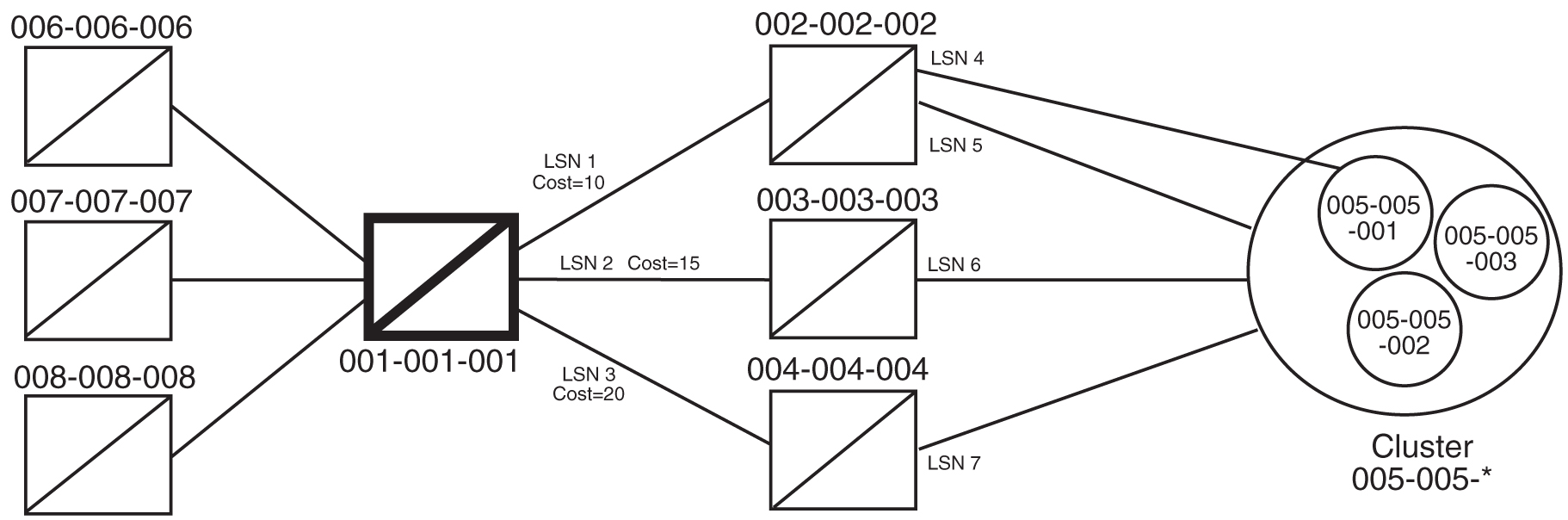
Table 2-7 Example Cluster Routing Information
| Route Table for Destination 005-005-001 | Route Table for Cluster 005-005-* | |
|---|---|---|
|
1 |
LSN 1, Cost=10 |
LSN 1, Cost=10 |
|
2 |
LSN 2, Cost=15 |
LSN 2, Cost=15 |
|
3 |
LSN 3, Cost=20 |
LSN 3, Cost=20 |
When the normal routes, linksets LSN 1 and LSN 2, become available, the EAGLE sends a preventive TFP for destination 005-005-001 and a preventive TCP for cluster 005-005-* to node 002-002-002, and starts routing messages to destination 005-005-001 and cluster 005-005-* using linkset LSN 1. The EAGLE broadcasts TFAs about destination 005-005-001 and TCAs about cluster 005-005-* to all other adjacent nodes.
- When linkset LSN 4 fails, node 002-002-002 sends a TFP for destination 005-005-001 to the EAGLE. Linkset LSN 4 is prohibited from carrying traffic from the EAGLE to destination 005-005-001. The EAGLE stops using linkset LSN 1 to send traffic to destination 005-005-001, performs forced rerouting, starts level 3 timer T11 for destination 005-005-001, and starts using linkset LSN 2 to send messages to destination 005-005-001. The EAGLE generates preventive TFPs about destination 005-005-001 to node 002-002-003. The preventive TCP for cluster 005-005-* sent to node 002-002-002 remains in effect.
When the level 3 timer T11 for destination 005-005-001 expires, TFRs are broadcast for destination 005-005-001 to nodes 004-004-004, 006-006-006, 007-007-007, and 008-008-008. Destination 005-005-001 is restricted.
- When linkset LSN 5 fails, node 002-002-002 sends a TCP for cluster 005-005-* to the EAGLE. Linkset LSN 5 is prohibited from carrying traffic from the EAGLE to cluster 005-005-*. The EAGLE stops using linkset LSN 1 to send traffic to cluster 005-005-*, performs forced rerouting, starts the level 3 timer T11 for cluster 005-005-*, and starts using linkset LSN 2 to send messages to cluster 005-005-*. The EAGLE sends preventive TCPs for cluster 005-005-* on linkset LSN 2. The EAGLE sends a TCR for cluster 005-005-* on linkset LSN 1, to allow cluster 005-005-* and destination 005-005-001 to send messages back to the EAGLE on linkset LSN 1. When the level 3 timer T11 for cluster 005-005-* expires, the EAGLE sends a TCR for cluster 005-005-* to nodes 004-004-004, 006-006-006, 007-007-007, and 008-008-008. Cluster 005-005-* is restricted.
- When linkset LSN 6 fails, node 003-003-003 sends a TCP for cluster 005-005-* to the EAGLE. The EAGLE performs forced rerouting, sends a preventive TFP for destination 005-005-001 and a TCP for destination 005-005-001 to node 004-004-004, and starts using linkset LSN 3 for sending messages to destination 005-005-001 and cluster 005-005-*.
- When linkset LSN 7 fails, node 004-004-004 sends a TCP for cluster 005-005-* to EAGLE. The EAGLE cannot send traffic to either destination 005-005-001 or cluster 005-005-*. The EAGLE broadcasts TCPs for cluster 005-005-* to nodes 002-002-002, 003-003-003, 004-004-004, 006-006-006, 007-007-007, and 008-008-008. Cluster 005-005-* and destination 005-005-001 are inaccessible.
- When linkset LSN 7 recovers, node 004-004-004 sends a TCA for cluster 005-005-* to the EAGLE. The EAGLE sends a preventive TCP for cluster 005-005-* to node 004-004-004, and starts using linkset LSN 3 to send traffic to cluster 005-005-*. The EAGLE sends a TCR for cluster 005-005-* to node 002-002-002. This allows cluster 005-005-* to send messages back to the EAGLE on linkset LSN 3. The EAGLE sends a preventive TCP for cluster 005-005-* to nodes 003-003-003 and 004-004-004. The EAGLE sends a TCR for cluster 005-005-* to nodes 006-006-006, 007-007-007, and 008-008-008. The EAGLE enables response method for destination 005-005-001, and starts a routeset test for destination 005-005-001 on linkset LSN 3. Cluster 005-005-* is restricted.
- When linkset LSN 6 recovers, node 003-003-003 sends a TCA for cluster 005-005-* to the EAGLE. The EAGLE performs controlled rerouting on cluster 005-005-*, sends a preventive TCP for cluster 005-005-* to node 003-003-003, and starts using linkset LSN 2 to send traffic to cluster 005-005-*. The EAGLE sends a TCR for cluster 005-005-* to node 004-004-004. The EAGLE starts a routeset test for destination 005-005-001 on linkset LSN 2.
- When linkset LSN 5 recovers, node 002-002-002 sends a TCA for cluster 005-005-* to the EAGLE. The EAGLE performs controlled rerouting, and starts using linkset LSN 1 to send traffic to cluster 005-005-*. The EAGLE sends a preventive TCP for cluster 005-005-* to node 002-002-002. The EAGLE broadcasts a TCA for cluster 005-005-* to nodes 003-003-003, 004-004-004, 006-006-006, 007-007-007, and 008-008-008. The EAGLE enables response method for destination 005-005-001, and starts a routeset test for destination 005-005-001 on linkset LSN 1. Cluster 005-005-* is allowed.
- In response to the routeset test, node 004-004-004 sends a TFA for destination 005-005-001 to the EAGLE. The EAGLE performs controlled rerouting, and starts using linkset LSN 3 to send traffic to destination 005-005-001. The EAGLE sends a preventive TFP for destination 005-005-001 to nodes 003-003-003 and 004-004-004. The EAGLE sends a TFR for destination 005-005-001 to node 002-002-002 that allows destination 005-005-001 to send messages back to the EAGLE on linkset LSN 1. The EAGLE broadcasts a TFR for destination 005-005-001 to nodes 006-006-006, 007-007-007, and 008-008-008. Destination 005-005-001 is restricted.
- In response to the routeset test, node 003-003-003 sends a TFA for destination 005-005-001 to the EAGLE. The EAGLE performs controlled rerouting and starts using linkset LSN 2 to send traffic to destination 005-005-001. The EAGLE sends a preventive TFP for destination 005-005-001 to node 003-003-003. The EAGLE sends a TFR for destination 005-005-001 to node 004-004-004.
- In response to the routeset test, node 002-002-002 sends a TFA for destination 005-005-001 to the EAGLE. The EAGLE performs controlled rerouting, and starts using linkset LSN 1 to send traffic to destination 005-005-001. The EAGLE sends a preventive TFP for destination 005-005-001 to node 002-002-002. The EAGLE sends a TFA for destination 005-005-001 to nodes 003-003-003, 004-004-004, 006-006-006, 007-007-007, and 008-008-008. Destination 005-005-001 is allowed.
Home Cluster Example
Figure 2-23 Home Cluster Example
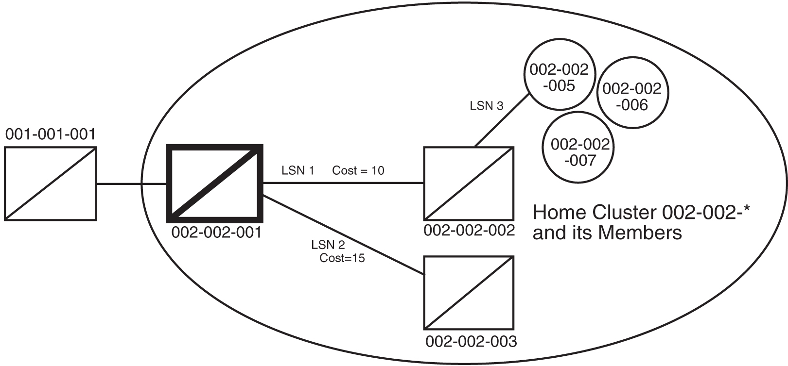
Table 2-8 Home Cluster Routing Information
| Route table for Destination 002-002-005 | Route table for cluster 002-002-* | |
|---|---|---|
|
1 |
LSN 1, Cost=10 |
LSN 1, Cost=10 |
|
2 |
LSN 2, Cost=15 |
LSN 2, Cost=15 |
A home cluster is a cluster point code that contains either the true point code or any capability point code of the EAGLE. For example, if the EAGLE’s true point code or any capability point code is 002-002-001 and a cluster 002-002-* is configured, then the cluster 002-002-* is a home cluster.
Provisioning a home cluster causes a profound impact on network management, regarding the home cluster as well as members of the cluster. These impacts are:
- Because the EAGLE is one of the accessible members of the home cluster, the EAGLE never transmits TCP or TCR messages regarding the home cluster, except for these:
- Preventive TCP – when starting to route to the cluster through an adjacent node
- Broadcast TCR – when the EAGLE starts routing on an alternate route for the entire cluster
- Back Routing TCR – to allow adjacent nodes on normal routes to route through the EAGLE, when the cluster is not accessible on the normal route
- Broadcast TCP – when the cluster (except the EAGLE itself) becomes inaccessible
- If individual members are provisioned for the home cluster, the EAGLE properly generates network management messages for these nodes, except that no TFRs can be sent from those members being routed on the alternate route to the EAGLE.
- Network management replies to the routeset test, and the response method generates the correct network management messages for the home cluster, its members, and unprovisioned member point codes.
- When the entire home cluster is being routed on the alternate route, the EAGLE generates a full point code response method TFR reply. In such a case, the EAGLE generates only one TFR for the very first member of the cluster for which MSU is received on each signaling link to that cluster.
- When the home cluster is inaccessible, the EAGLE generates one response TFP, at an interval equal to the value of the level 3 timer T8 for the members of the home cluster. If the EAGLE keeps receiving traffic for the home cluster, the EAGLE sends response TFPs for all members of the cluster.
This makes network management unreliable for the home cluster and its members.
When the normal routes, linksets LSN 1 and LSN 2, become available, the EAGLE sends a preventive TFP for destination 002-002-005 to node 002-002-002, and starts sending messages to destination 002-002-005 and cluster 002-002-* using linkset LSN 1. No preventive messages are sent for cluster 002-002-*. The EAGLE broadcasts a TFA for destination 002-002-005 and a TCA for cluster 002-002-* to all other adjacent nodes.
- Node 002-002-002 sends an MSU containing the destination point code 002-002-006 on linkset LSN 1. The EAGLE responds with a response preventive TFP for destination 002-002-006 to node 002-002-002.
- When linkset LSN 3 fails, node 002-002-002 sends a TFP for destination 002-002-005 to the EAGLE. The EAGLE stops using linkset LSN 1 to send traffic to destination 002-002-005, performs forced rerouting, starts the level 3 timer T11 for destination 002-002-005, and starts using linkset LSN 2 to send traffic to destination 002-002-005. The EAGLE generates a preventive TFP for destination 002-002-005 to node 002-002-003. When the level 3 timer T11 for destination 002-002-005 expires, TFRs for destination 002-002-005 are broadcast to nodes 002-002-003 and 001-001-001. Destination 002-002-005 is restricted.
- Node 002-002-002 sends an MSU containing the destination point code 002-002-005 on linkset LSN 1. The EAGLE responds with a response preventive TFP for destination 002-002-005 to node 002-002-002, because no member of a home cluster is allowed to route messages back to the EAGLE.
- When linkset LSN 1 fails, the EAGLE stops using linkset LSN 1 to send traffic to cluster 002-002-*, performs forced rerouting, starts the level 3 timer T11 for cluster 002-002-*, and starts using linkset LSN 2 to send traffic to cluster 002-002-*. Cluster 002-002-* is restricted. No preventive or broadcast messages are sent, and no member of the cluster is allowed to send messages back to the EAGLE.
- Node 001-001-001 sends an MSU containing the destination point code 002-002-006. The EAGLE responds with a response TFR for destination 002-002-006 to node 001-001-001. The MSU is routed on linkset LSN 2.
- Node 001-001-001 sends an MSU containing the destination point code 002-002-005. The EAGLE responds with a response TFR for destination 002-002-005 to node 001-001-001. The MSU is routed on linkset LSN 2.
- Node 001-001-001 sends an MSU containing the destination point code 002-002-007 and receives no response. The MSU is routed on linkset LSN 2.
- When linkset LSN 2 fails, destination 002-002-005 and cluster 002-002-* are prohibited. The EAGLE broadcasts a TFP for destination 002-002-005 to node 001-001-001.
- Node 001-001-001 sends an MSU containing the destination point code 002-002-007. The EAGLE responds with a TFP for destination 002-002-007 to node 001-001-001, and starts the level 3 timer T8 for cluster 002-002-*.
- Node 001-001-001 sends an MSU containing the destination point code 002-002-006, and receives no response until the level 3 timer T8 expires.
- Node 001-001-001 sends an MSU containing the destination point code 002-002-005. The EAGLE responds with a TFP for destination 002-002-005 to node 001-001-001, and starts the level 3 timer T8 for destination 002-002-005.
- Node 001-001-001 sends an MSU containing the destination point code 002-002-006. After the level 3 timer T8 for cluster 002-002-* expires, the EAGLE responds with a TFP for destination 002-002-006 to node 001-001-001, and starts the level 3 timer T8 for cluster 002-002-*.
2.16 Nested Cluster Routing
When a node is switching traffic to remote (non-adjacent) nodes, it is possible that an STP is using at least one route that is different from the other members of a cluster. Typically, this occurs when the node is directly connected to the member of a cluster, such as when an STP has A-links or E-links that are connected to a member. The nested cluster routing feature provides a mechanism that allows both cluster and member routes to be provisioned in the same cluster.
Nested Clusters and Cluster Members
The cluster routing and management feature requires that routes to a cluster and members of that cluster be in the same routeset. With the nested cluster routing feature, however, users can have certain members of the provisioned cluster with different full point code routesets. This different routeset may be totally different, partially different, or exactly the same.
With the nested cluster routing feature, routes to these members can be changed, deleted, or added. Deletion of a full point code route entry within a cluster will result in the member using the cluster entry for routing. Deletion of a cluster route entry will not delete the full point code route entry. This holds true even if the full point code entry and the cluster have the same route.
The EAGLE sends cluster network management messages (TCA, TCR, TCP) based on the least restrictive of the cluster's routeset status, and the routeset status of any full point code entries within the cluster.
The nested cluster routing feature provides a new routing model. The EAGLE allows several routing models. Table 2-9 describes coupling between the cluster and its members. Coupling describes the relationship between the cluster and member routes.
Table 2-9 Routing Models
| System Routing Model | Characteristics | Issues and Resolution |
|---|---|---|
|
Full Point Code Routing (FPR) No coupling |
The EAGLE behaves as a full point code router when the Cluster Routing and Management Diversity feature is off. Only full point code destinations are provisioned. The EAGLE never generates TCx messages concerning clusters of provisioned members. Received TCx messages are applied to all members of the concerned cluster. |
No issues. There is no coupling between cluster status and member statuses due to the lack of clusters. |
|
Cluster Routing (CR) No coupling NCAI=No |
With the Cluster Routing and Management Diversity feature on, the EAGLE allows the provisioning of cluster destinations. For cluster destinations, only cluster destinations are provisioned. The EAGLE generates TCx messages only for provisioned cluster destinations. All received TCx messages are applied to concerned cluster entry, if it exists. Otherwise, it is applied to all individual members. |
No issues. There is no coupling between cluster status and member status due to the lack of members belonging to provisioned cluster. |
|
Cluster Routing and Management Diversity (CRMD) Full coupling NCAI=No |
In this mode, the EAGLE allows provisioning of clusters as well as members of same clusters. Here cluster and member have the same routeset, and they are fully coupled. All TCx messages are applied to members, and TCx messages generated by the EAGLE reflect member status. In this mode, the member status cannot be less restrictive than the cluster. |
No issues regarding network management message generation and processing. Cluster and members cannot have a different routeset, and thus E-links cannot be provisioned for members of a cluster. |
|
Nested Cluster Routing No coupling NCAI=Yes |
In this mode, if the |
There is an issue regarding broadcasting network management messages. Because members can be less restricted than the cluster, the broadcast of cluster messages (TCA, TCR, TCP) is based on the least restrictive of the following:
|
Administration
The nested cluster routing feature is provisioned using the ncai parameter of either the ent-dstn or chg-dstn commands. The ncai parameter can only be specified for cluster point codes.
In order to specify the ncai parameter, both the Cluster Routing and Management Diversity and the nested cluster routing features must be on. If the ncai parameter is yes, the EAGLE allows certain members of the provisioned cluster to have a different full point code routeset.
If the ncai parameter is no, standard command-handler rules apply (any full point code routeset within a cluster must have the same routeset as the cluster). If ncai parameter is yes, new command-handler rules apply (full point code routeset can be different from the cluster routeset). Figure 2-24 provides an example of provisioning a nested cluster and its associated members.
Nested Cluster Routing Rules of Operations
The following rules apply to nested clusters (cluster entries with the ncai parameter set to yes):
- The EAGLE allows the user to enter a full point code routeset entry even if the point code is a member of a cluster that has a different routeset. For example, in Figure 2-24, the provisioned member 5-5-1 has a different routeset than the cluster's routeset.
- When the EAGLE broadcasts network management messages relating to the cluster, the EAGLE uses the least restricted of the following to determine which cluster message (TCA, TCR, TCP) to send:
- The cluster's routeset status
- The routeset status of any full point code entries within the cluster
For example, in Figure 2-24, if linkset LSB fails, a TCP message for cluster 5-5-* is not broadcast because the least restrictive status of provisioned member 5-5-1 is allowed.
- The EAGLE does not send preventive TCPs when it begins routing toward a nested cluster. The EAGLE sends response-method preventive TFPs if it receives an MSU and there is danger of circular routing. For example, in Figure 2-24, the EAGLE does not send a preventive TCP for cluster 5-5-* when routing to cluster 5-5-* over linkset LSB. However, if the EAGLE receives an MSU on linkset LSB destined for node 5-5-2, the EAGLE discards the MSU and sends a TFP to node B concerning node 5-5-2.
Note:
The EAGLE will still send preventive TFPs when it starts routing toward a full point code member of a nested cluster. - The EAGLE replies to RCx cluster routeset test messages, using the less restrictive routeset status as indicated in rule #2.
- The EAGLE replies to RSx full point code routeset messages, using the full point code's routeset status and the danger of circular routing.
- Response method TFP or TFR is used when the cluster destination is more restrictive than a full point code member. The modified TFP response method will send no more than one TFP per cluster member during the time period defined by the level 3 T8 timer. The modified TFR response method sends no more than one response TFR per cluster member.
Nested Cluster Routing Example
Figure 2-24 provide an example of nested cluster routing. Table 2-10 and Table 2-11 show the routing tables for the cluster point code and one of the members of the cluster point code. Table 2-12 shows what actions the EAGLE takes when the linksets in a nested cluster configuration fail and recover. The actions in Table 2-12 are based on the example nested cluster routing configuration shown in Figure 2-24.
Figure 2-24 Nested Cluster Routing Sample Configuration
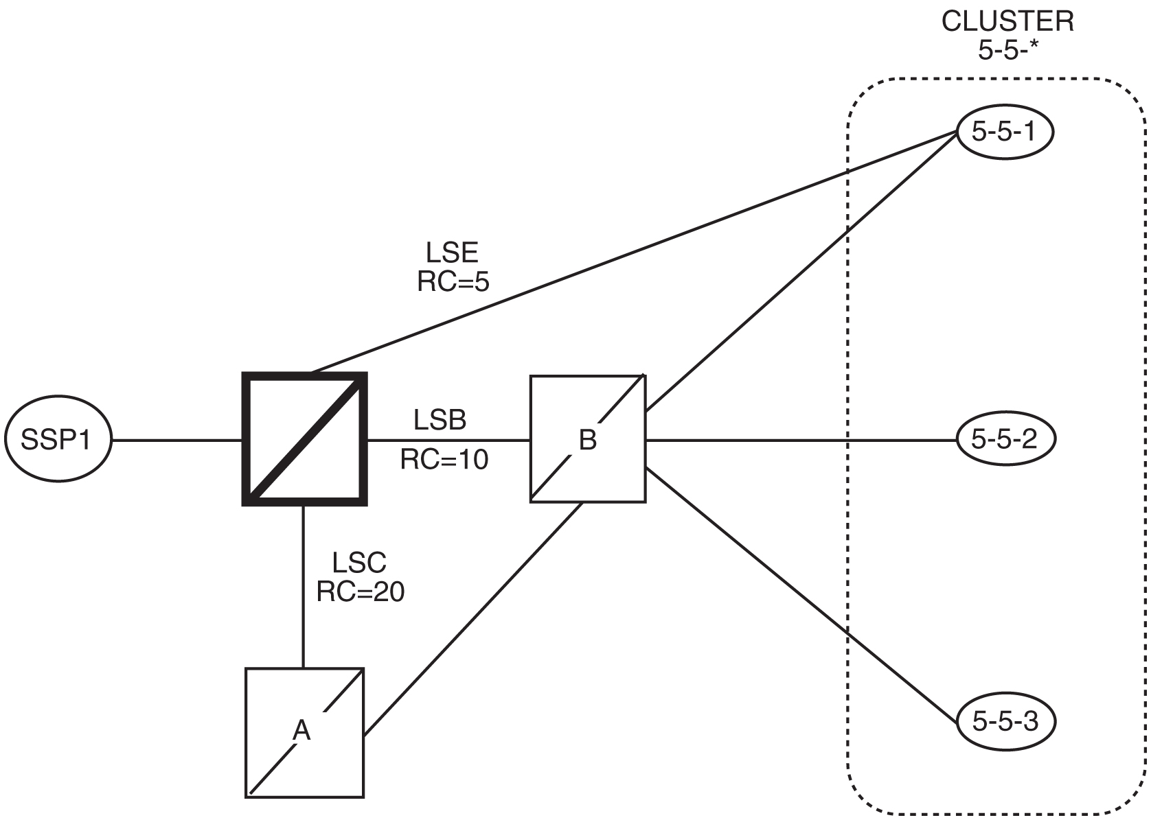
Table 2-10 Routing Table for Nested Cluster 5-5-*
| Linkset Name | Route DPC | Cost Value of the Route |
|---|---|---|
|
LSB |
5-5-* |
10 |
|
LSC |
5-5-* |
20 |
Table 2-11 Routing Table for Full Point Code Member 5-5-1
| Linkset Name | Route DPC | Cost Value of the Route |
|---|---|---|
|
LSE |
5-5-1 |
5 |
|
LSB |
5-5-1 |
10 |
|
LSC |
5-5-1 |
20 |
Table 2-12 Example of Nested Cluster Routing Failure and Recovery Actions
| Event | Action |
|---|---|
|
All linksets are up and all routes are available. |
The EAGLE does not send a preventive TCP for cluster 5-5-* to node B because cluster 5-5-* is a nested cluster. Messages are routed to SSP 5-5-1 using linkset LSE and to cluster 5-5-* using linkset LSB. The EAGLE broadcasts TCAs concerning cluster 5-5-* to nodes SSP1, SSP 5-5-1, node A, and node B. |
|
The linkset between node B and SSP 5-5-2 fails. Node B sends a TFP concerning SSP 5-5-2. |
The EAGLE creates an x-list entry for point code 5-5-2 and marks it prohibited on linkset LSB. The EAGLE broadcasts TFPs to SSP1, SSP 5-5-1 and node A and sends response method TFP concerning point code 5-5-2. The EAGLE starts an RSP for SSP 5-5-2 on linkset LSB. |
|
The linkset between node B and SSP 5-5-1 fails. Node B sends a TFP for SSP 5-5-1 to the EAGLE. |
The EAGLE marks full point code 5-5-1 as prohibited on linkset LSB. The EAGLE routes the traffic to SSP 5-5-1 using linkset LSE. The EAGLE starts an RSP for SSP 5-5-1 on linkset LSB. |
|
The linkset between node B and SSP 5-5-2 recovers, and node B sends a TFA for SSP 5-5-2 to the EAGLE. |
The EAGLE removes point code 5-5-2 from the exception list. The status of linkset LSB is changed from prohibited to allowed. Traffic is routed to SSP 5-5-2 using linkset LSB. The EAGLE broadcasts a TFA concerning SSP 5-5-2 to SSP1, SSP 5-5-1 and node A. The EAGLE sends a preventive TFP concerning SSP 5-5-2 to node B. |
|
The linkset between node B and SSP 5-5-1 recovers, and node B sends a TFA concerning SSP 5-5-1 to the EAGLE. |
The EAGLE marks full point code 5-5-1 as allowed on linkset LSB. |
|
Linkset LSB fails. |
The EAGLE stops using linkset LSB to send traffic to cluster 5-5-*. Linkset LSB is marked prohibited, forced rerouting is performed, level 3 timer T11 for cluster 5-5-* is started, and starts using linkset LSC to send traffic to cluster 5-5-*. The EAGLE marks cluster 5-5-* restricted on linkset LSC for all members of cluster 5-5-* except full point code 5-5-1. When level 3 timer T11 expires, a TFR response method is sent for all members of cluster 5-5-* except full point code 5-5-1. |
|
SSP1 sends an MSU with DPC=5-5-2. |
The EAGLE responds with TFR concerning SSP 5-5-2 to SSP1. The MSU is routed on linkset LSC. |
|
SSP1 sends an MSU with DPC=5-5-1. |
The EAGLE routes the MSU to SSP 5-5-1 using linkset LSE. |
|
Linkset LSB recovers. |
The EAGLE stops using linkset LSC to send traffic to cluster 5-5-*, performs controlling rerouting on cluster 5-5-*, marks cluster 5-5-* as allowed on linkset LSB, and starts routing traffic to cluster 5-5-* using linkset LSB. |
|
The SSP sends a routeset test (RSR) concerning SSP 5-5-2 to the EAGLE. |
The EAGLE responds with a TFA concerning SSP 5-5-2. |
|
Linkset LSC fails. |
The EAGLE stops using linkset LSC to send traffic to cluster 5-5-* or full point code 5-5-1, and marks cluster 5-5-* and full point code 5-5-1 as prohibited on linkset LSC. |
|
Linkset LSC recovers. |
The EAGLE marks cluster 5-5-* and full point code 5-5-1 as allowed on linkset LSC. |
|
Linkset LSE fails. |
The EAGLE stops using linkset LSE to send traffic to SSP-5-5-1, marks SSP 5-5-1 as prohibited on linkset LSE, performs forced rerouting, starts level 3 timer T11 concerning SSP 5-5-1, sends preventive TFP concerning SSP 5-5-1 to node B, and starts using linkset LSB to send traffic to full point code 5-5-1. The EAGLE marks full point code 5-5-1 as restricted on linkset LSB. When level 3 timer T11 expires, a TFR concerning SSP 5-5-1 is sent to SSP1 and node A. |
|
SSP1 sends an MSU with the DPC 5-5-2. |
The EAGLE routes the MSU to SSP 5-5-2 using linkset LSB. |
|
SSP1 sends an MSU with the DPC 5-5-1. |
The EAGLE responds with a TFR concerning SSP 5-5-1 to SSP1. The MSU is routed to SSP 5-5-1 using linkset LSB. |
|
Linkset LSE recovers. |
The EAGLE stops using linkset LSB to send traffic to SSP 5-5-1, performs controlling rerouting on full point code 5-5-1, marks full point code 5-5-1 as allowed on linkset LSE, and starts routing traffic to full point code 5-5-1 using linkset LSE. The EAGLE broadcasts a TFA for SSP 5-5-1 to SSP1, node A, and node B. |
Limitations of the Nested Cluster Routing Feature
The EAGLE only supports a maximum of 200 nested cluster destinations. This limit does not apply to non-nested clusters (clusters with the ncai parameter set to no).
If a cluster is more restricted than a member, the EAGLE broadcasts the status of the least restricted member, and relies on response method for members of the cluster that do not have a full point code entry.
The EAGLE does not broadcast preventive TCPs for nested cluster destinations. Because the EAGLE does not send preventive TCPs when it begins routing toward a nested cluster, circular routing can occur. The EAGLE sends response method TFPs if it receives an MSU when there is a danger of circular routing.
2.17 Adding a Cluster Point Code
This procedure is used to add a cluster point code for the Cluster Routing and Management Diversity (CRMD) feature, and nested cluster point codes for the nested cluster routing feature to the database, using the ent-dstn command.
To change the attributes of an existing cluster point code, go to the Changing the Attributes of a Cluster Point Code procedure.
Note:
Cluster entries can only be provisioned as ANSI destination point codes. Cluster entries cannot be provisioned for ITU international or ITU national destination point codes, and cannot be provisioned as a proxy point code. The ANSI alias point code for an ITU international or ITU national destination point code must be a full point code. An ANSI private point code must be a full point code.To remove a cluster point code from the database, go to the Removing a Destination Point Code procedure.
The Cluster Routing and Management Diversity feature must be turned on.
The ent-dstn command uses these parameters:
:dpc/dpca – The destination point code being added to the database.
Note:
See Point Code Formats for a definition of the point code types that are used on the EAGLE.Note:
Alias point codes (aliasi/aliasn/aliasn24) and secondary point codes (spc/spca) cannot be specified for a cluster point code.
:clli – The Common Language Location Identifier assigned to this point code.
:domain – The network in which the destination entity or node exists, SS7.
Note:
Specifying:domain=ss7 is the only valid entry for cluster destinations.
:bei – Broadcast exception indicator that indicates whether transfer-prohibited (TFP) messages will be broadcast from this node. The bei=yes parameter means TFPs will not be broadcast. The bei=no parameter means TFPs will be broadcast.
:ipgwapc– (ANSI networks only)IP Gateway Adjacent Point Code indicator. Specify ipgwapc=yes to provide SS7 linkset definition compatibility for gateway connections to IP-SCPs. The default is ipgwapc=no.
:elei – For cluster point codes only. Specifies whether or not the EAGLE maintains a dynamic status exception list for each cluster route that may be used to reach the member signaling points making up the cluster. The elei=yes parameter means the EAGLE does not maintain an exception list for the cluster point code specified by the dpc parameter. The elei=no parameter means the EAGLE does maintain an exception list for the cluster point code specified by the dpc parameter. The default value for the elei parameter is no.
:ncai – The nested-cluster-allowed indicator specifies whether or not the route to the cluster point code can be different from the route to a point code that is a member of the cluster point code. A point code is a member of a cluster point code if it has the same network identifier (NI) and network cluster (NC) values as the cluster point code. This parameter can be specified only for cluster point codes.
If the ncai parameter value is yes, the cluster point code is a nested cluster point code. Point codes that are members of this cluster point code can be assigned to routesets that are different from the routeset assigned to the cluster point code.
If the ncai parameter value is no, the cluster point code is not a nested cluster point code. Point codes that are members of this cluster point code must be assigned to the same routeset assigned to the cluster point code.
The default value for the ncai parameter is no.
See the Nested Cluster Routing section for more information on the nested cluster routing feature.
:nprst - NM bits reset. This parameter specifies whether the NM bits in an ITU IAM message should be set to 00. This parameter has two values.
off- Do not set NM bits to 00 in an ITU IAM message if thenptypeoption value in thertrv-tifoptsoutput isnm.on- Set the NM bits to 00 in an ITU IAM message if thenptypeoption value in thertrv-tifoptsoutput isnm.The default value for this parameter is
off.
:rcause - Release cause. This parameter specifies the condition that triggers the sending of a Release message. This parameter has these values.
- 0 - 127
none- use the values specified for thercausenpandrcausepfxparameters in thertrv-tifoptsoutput.The default value for this parameter is
none.If the
rlcopcparameter value in thertrv-tipoptsoutput is on and a value of 0-127 is specified for thercauseparameter, then thercauseparameter value overrides the values specified for thercausenpandrcausepfxparameters in thertrv-tifoptsoutput.
:splitiam - This parameter specifies how and when to split an ITU IAM message into one IAM message and one SAM message. This parameter has these values.
- 15-31 - The maximum number of CdPN digits allowed in the IAM message before the splitting occurs. The remaining digits, up to a total of 32, are encoded in the SAM message.
none- the value specified for thesplitiamparameter in thertrv-tifoptsoutput is used to determine when to split the IAM message.The default value for this parameter is
none.
nprst or rcause parameters, the TIF Number Portability feature, part number 893018901, must be enabled. To specify the splitiam parameter, at least one of these features must be enabled.
- TIF Number Portability - part number 893018901
- TIF SCS Forwarding - part number 893022201
- TIF Simple Number Substitution - part number 893024001
- TIF Additional Subscriber Data - part number 893024501
- TIF Generic Routing Number - part number 893025501
- TIF Selective Screening - part number 893040201
The status of these features is shown in the rtrv-ctrl-feat output. Perform the procedures in TIF User's Guide to enable these features.
:sccpmsgcnv - The sccpmsgcnv parameter controls SCCP UDT(S)/XUDT(S) message conversion for the specified destination. This parameter can be specified only if the XUDT UDT Conversion feature is enabled and turned on. The rtrv-ctrl-feat output shows the status of the XUDT UDT Conversion feature. If the XUDT UDT Conversion feature is not enabled or turned on, perform the "Activating the XUDT UDT Conversion Feature" procedure in Database Administration - GTT User's Guide to enable and turn on the XUDT UDT Conversion feature. This parameter contains these values.
- none - SCCP UDT(S)/XUDT(S) message conversion is not required on messages for the destination. This value is the default value for this parameter.
- udt2xudt - All UDT(S) messages for the destination are converted to XUDT(S) messages.
- xudt2udt - All non-segmented XUDT(S) messages for the destination are converted to UDT(S) messages. Segmented XUDT(S) messages for the destination are not converted to UDT(S ) messages.
- sxudt2udt - All segmented and non-segmented XUDT(S) messages for the destination are converted to UDT(S) messages.
The ent-dstn command also contains the homescp and homesmsc parameters. The values for these parameters are yes and no. The value no is the default value for these parameters. The value yes for these parameters cannot be specified for a cluster point code. To specify the value yes for these parameters, perform the Adding a Destination Point Code or Changing a Destination Point Code procedures.
To add a cluster point code to the database, the Cluster Routing and Management Diversity feature must be on. The ncai parameter can be specified for the cluster point code only if both the Cluster Routing and Management Diversity and nested cluster routing features are on. This is shown by the entries CRMD = on (for the Cluster Routing and Management Diversity feature) and NCR = on (for the nested cluster routing feature) in the rtrv-feat command output.
The domain of the cluster point code must be SS7 (domain=ss7).
To enter an ANSI point code, an ANSI self ID for the EAGLE must be defined. This can be verified with the rtrv-sid command. The ANSI self ID is shown in the PCA field in the rtrv-sid command output. If no values are shown in the PCA field of the rtrv-sid command output, go to Changing the Self-Identification of the EAGLE procedure to add the ANSI Self ID of the EAGLE.
The actual number of destination point codes that can be configured in the database is set by the mtpdpcq parameter of the chg-stpopts command, and is shown in the MTPDPCQ field in the rtrv-stpopts command output. See 13.
If the 5000 Routes feature is not on, and 6000, 7000, 8000, or 10,000 routesets are not enabled, the sum of the mtpdpcq and mtpxlq parameters cannot exceed 2500. The range of values for the mtpdpcq and mtpxlq parameters is 500 to 2000.
If the 5000 Routes feature is on, and 6000, 7000, 8000, or 10,000 routesets are not enabled the sum of the mtpdpcq and mtpxlq parameters cannot exceed 5500. The range of values for the mtpdpcq and mtpxlq parameters is 500 to 5000.
If 6000 routesets are enabled, the sum of the mtpdpcq and mtpxlq parameters cannot exceed 6500. The range of values for the mtpdpcq and mtpxlq parameters is 500 to 6000.
If 7000 routesets are enabled, the sum of the mtpdpcq and mtpxlq parameters cannot exceed 7500. The range of values for the mtpdpcq parameter is 500 to 7000. The range of values for the mtpxlq parameter is 500 to 6000.
If 8000 routesets are enabled, the sum of the mtpdpcq and mtpxlq parameters cannot exceed 8500. The range of values for the mtpdpcq parameter is 500 to 8000. The range of values for the mtpxlq parameter is 500 to 6000.
If 10,000 routesets are enabled, the sum of the mtpdpcq and mtpxlq parameters cannot exceed 10500. The range of values for the mtpdpcq and mtpxlq parameters is 500 to 10,000.
Note:
For more information on the destination point code quantities, go to the Changing the DPC Quantity procedure.If the ncai parameter value is yes, the EAGLE can have a maximum of 200 nested cluster point codes in the database.
The value of the clli parameter cannot be in the DPC table and cannot match the CLLI of the EAGLE. Verify this by entering the rtrv-dstn and the rtrv-sid commands, shown in 3 and 4. If the value of the clli parameter matches any CLLI values in either of these outputs, choose another value for the clli parameter that does not match any CLLIs shown in either of these command outputs.
If the PCTYPE field of the rtrv-sid command output contains the entry ANSI, and the network value of the destination point codes specified by the ent-dstn command, is from 0 to 5, the cluster value of that point code must be from 1 to 255. If the network value of that point code is from 6 to 255, the cluster value of that point code must be from 0 to 255.
To add a cluster point code to the database when the database contains point codes that are members of the cluster, the linkset type used by the routes to the member point codes must be either B, C, or D. For example, you wish to add the cluster point code 004-004-* and the database contains point codes 004-004-001 and 004-004-002. When cluster point code is added, point codes 004-004-001 and 004-004-002 would become members of the cluster point code 004-004-*. If point codes 004-004-001 or 004-004-002 are the destination point codes of routes, and the linkset type of these routes are either A or E, the cluster point code 004-004-* cannot be added to the database. The linkset type of these routes must be changed to either B, C, or D to add cluster point code 004-004-* to the database. To change the linkset type of a linkset, perform the Changing an SS7 Linkset procedure.
The examples in this procedure are used to enter the cluster point code 111-011-* and the nested cluster point code 030-045-*.
Canceling the RTRV-DSTN Command
Because the rtrv-dstn command used in this procedure can output information for a long period of time, the rtrv-dstn command can be canceled and the output to the terminal stopped. There are three ways that the rtrv-dstn command can be canceled:
- Press the
F9function key on the keyboard at the terminal where thertrv-dstncommand was entered. - Enter the
canc-cmdwithout thetrmparameter at the terminal where thertrv-dstncommand was entered. - Enter the
canc-cmd:trm=<xx>, where<xx>is the terminal where thertrv-dstncommand was entered, from another terminal other than the terminal where thertrv-dstncommand was entered. To enter thecanc-cmd:trm=<xx>command, the terminal must allow Security Administration commands to be entered from it and the user must be allowed to enter Security Administration commands. The terminal’s permissions can be verified with thertrv-secu-trmcommand. The user’s permissions can be verified with thertrv-userorrtrv-secu-usercommands.
For more information about the canc-cmd command, refer to Commands User's Guide.
Figure 2-25 Adding a Cluster Point Code
2.18 Changing the Attributes of a Cluster Point Code
This procedure is used to change the attributes of a cluster point code in the database, using the chg-dstn command.
Note:
Cluster entries can be provisioned only as ANSI destination point codes. Cluster entries cannot be provisioned for ITU international or ITU national destination point codes, and cannot be provisioned as a proxy point code. The ANSI alias point code for an ITU international or ITU national destination point code must be a full point code. An ANSI private point code must be a full point code.To add a new cluster point code to the database, perform the Adding a Cluster Point Code procedure.
To remove a cluster point code from the database, perform the Removing a Destination Point Code procedure.
The cluster point code to be changed must be in the database.
The chg-dstn command uses these parameters:
:dpc/dpca – The destination point code in the database being changed
Note:
See Point Code Formats for a definition of the point code types that are used on the EAGLE.Note:
Alias point codes (aliasi/aliasn/aliasn24) and secondary point codes (spc/spca) cannot be specified for a cluster point code.
:clli – The Common Language Location Identifier assigned to this point code
:domain – The network in which the destination entity or node exists- SS7.
:bei – Broadcast exception indicator that indicates whether transfer-prohibited (TFP) messages will be broadcast from this node. The bei=yes parameter means TFPs will not be broadcast. The bei=no parameter means TFPs will be broadcast.
:ipgwapc – (ANSI networks only)IP Gateway Adjacent Point Code indicator. Specify ipgwapc=yes to provide SS7 linkset definition compatibility for gateway connections to IP-SCPs. The default is ipgwapc=no.
:elei – For cluster point codes only. Specifies whether or not the EAGLE maintains a dynamic status exception list for each cluster route that may be used to reach the member signaling points making up the cluster. The elei=yes parameter means the EAGLE does not maintain an exception list for the cluster point code specified by the dpc parameter. The elei=no parameter means the EAGLE does maintain an exception list for the cluster point code specified by the dpc parameter.
:ncai – The nested-cluster-allowed indicator specifies whether or not the route to the cluster point code can be different from the route to a point code that is a member of the cluster point code. A point code is a member of a cluster point code if it has the same network identifier (NI) and network cluster (NC) values as the cluster point code. This parameter can be specified only for cluster point codes.
If the ncai parameter value is yes, the cluster point code is a nested cluster point code. Point codes that are members of this cluster point code can be assigned to routesets that are different from the routeset assigned to the cluster point code.
If the ncai parameter value is no, the cluster point code is not a nested cluster point code. Point codes that are members of this cluster point code must be assigned to the same routeset assigned to the cluster point code.
Refer to the Nested Cluster Routing section for more information on the nested cluster routing feature.
:nprst - NM bits reset. This parameter specifies whether the NM bits in an ITU IAM message should be set to 00. This parameter has two values.
off- Do not set NM bits to 00 in an ITU IAM message if thenptypeoption value in thertrv-tifoptsoutput isnm.on- Set the NM bits to 00 in an ITU IAM message if thenptypeoption value in thertrv-tifoptsoutput isnm.The default value for this parameter is
off.
:rcause - Release cause. This parameter specifies the condition that triggers the sending of a Release message. This parameter has these values.
- 0 - 127
none- use the values specified for thercausenpandrcausepfxparameters in thertrv-tifoptsoutput.The default value for this parameter is
none.If the
rlcopcparameter value in thertrv-tipoptsoutput is on and a value of 0-127 is specified for thercauseparameter, then thercauseparameter value overrides the values specified for thercausenpandrcausepfxparameters in thertrv-tifoptsoutput.
:splitiam - This parameter specifies how and when to split an ITU IAM message into one IAM message and one SAM message. This parameter has these values.
- 15-31 - The maximum number of CdPN digits allowed in the IAM message before the splitting occurs. The remaining digits, up to a total of 32, are encoded in the SAM message.
none- the value specified for thesplitiamparameter in thertrv-tifoptsoutput is used to determine when to split the IAM message.The default value for this parameter is
none.
nprst or rcause parameters, the TIF Number Portability feature, part number 893018901, must be enabled. To specify the splitiam parameter, at least one of these features must be enabled.
- TIF Number Portability - part number 893018901
- TIF SCS Forwarding - part number 893022201
- TIF Simple Number Substitution - part number 893024001
- TIF Additional Subscriber Data - part number 893024501
- TIF Generic Routing Number - part number 893025501
The status of these features is shown in the
rtrv-ctrl-featoutput. Perform the procedures in TIF User's Guide to enable these features.
:sccpmsgcnv - The sccpmsgcnv parameter controls SCCP UDT(S)/XUDT(S) message conversion for the specified destination. This parameter can be specified only if the XUDT UDT Conversion feature is enabled and turned on. The rtrv-ctrl-feat output shows the status of the XUDT UDT Conversion feature. If the XUDT UDT Conversion feature is not enabled or turned on, perform the "Activating the XUDT UDT Conversion Feature" procedure in Database Administration - GTT User's Guide to enable and turn on the XUDT UDT Conversion feature. This parameter contains these values.
- none - SCCP UDT(S)/XUDT(S) message conversion is not performed on messages for the destination.
- udt2xudt - All UDT(S) messages for the destination are converted to XUDT(S) messages.
- xudt2udt - All non-segmented XUDT(S) messages for the destination are converted to UDT(S) messages. Segmented XUDT(S) messages for the destination are not converted to UDT(S ) messages.
- sxudt2udt - All segmented and non-segmented XUDT(S) messages for the destination are converted to UDT(S) messages.
The chg-dstn command also contains the homescp and homesmsc parameters. The values for these parameters are yes and no. The value no is the system default value for these parameters. The value yes for these parameters cannot be specified for a cluster point code. To specify the value yes for these parameters, perform the Adding a Destination Point Code or Changing a Destination Point Code procedures.
The value of the clli parameter cannot be in the DPC table and cannot match the CLLI of the EAGLE. Verify this by entering the rtrv-dstn and the rtrv-sid commands, shown in 1 and 3. If the value of the clli parameter matches any CLLI values in either of these outputs, choose another value for the clli parameter that does not match any CLLIs shown in either of these command outputs.
If a nested cluster point code is changed to a non-nested cluster point code (the value of the ncai parameter is changed from yes to no), any point codes that are members of this point code must be assigned to the same routeset as the cluster point code.
The elei (exception list exclusion indicator) parameter can be specified only for a cluster destination point code. Cluster destination point codes and the elei parameter can be specified only if the Cluster Routing and Management Diversity feature is turned on. Verify this with the rtrv-feat command. If the Cluster Routing and Management Diversity feature is turned on, the CRMD field should be set to on. If the Cluster Routing and Management Diversity feature is not turned on, enter the chg-feat:crmd=on command. For more information on the Cluster Routing and Management Diversity feature, refer to the Cluster Routing and Management Diversity (CRMD) section.
The ncai parameter can be specified only if the Nested Cluster Routing feature is on. This can be verified with the entry NCR = on in the rtrv-feat command output. If the nested cluster routing feature is not turned on, enter the chg-feat:ncr=on command. For more information on the nested cluster routing feature, refer to the Nested Cluster Routing section.
Note:
Once the Cluster Routing and Management Diversity and nested cluster routing features are turned on with thechg-feat command, they cannot be turned off.
The Cluster Routing and Management Diversity and nested cluster routing features must be purchased before you turn these features on with the chg-feat command. If you are not sure if you have purchased the Cluster Routing and Management Diversity and nested cluster routing features, contact your Sales Representative or Account Representative.
The examples in this procedure are used to change the attributes of the cluster point code 030-003-*.
Canceling the RTRV-DSTN and RTRV-RTE Commands
Because thertrv-dstn and rtrv-rte commands used in this procedure can output information for a long period of time, the rtrv-dstn and rtrv-rte commands can be canceled and the output to the terminal stopped. There are three ways that the rtrv-dstn and rtrv-rte commands can be canceled:
- Press the
F9function key on the keyboard at the terminal where thertrv-dstnorrtrv-rtecommand was entered. - Enter the
canc-cmdwithout thetrmparameter at the terminal where thertrv-dstnorrtrv-rtecommand was entered. - Enter the
canc-cmd:trm=<xx>, where<xx>is the terminal where thertrv-dstnorrtrv-rtecommand was entered, from another terminal other than the terminal where thertrv-dstnorrtrv-rtecommand was entered. To enter thecanc-cmd:trm=<xx>command, the terminal must allow Security Administration commands to be entered from it and the user must be allowed to enter Security Administration commands. The terminal’s permissions can be verified with thertrv-secu-trmcommand. The user’s permissions can be verified with thertrv-userorrtrv-secu-usercommands.
For more information about the canc-cmd command, refer to Commands User's Guide.
Figure 2-26 Changing the Attributes of a Cluster Point Code
2.19 Network Routing
Network routing allows the user to provision a single routeset that can used for all MSUs destined to members of that network. The advantages of network routing are:
- Reduces the number of entries in the route table
- Allows routing to members of a network without having to add those members to the route table
A EAGLE user can connect to a remote network by provisioning a single route table element. As the remote network grows, the EAGLE user does not have to add new route table entries for each new point code in the remote network.
Note:
Network routing can be used only with ANSI point codes. A network routing point code cannot be provisioned as a proxy point code.Types of Routing Strategies Available
The EAGLE currently allows a user to provision two types of routing strategies:
- Full point code routing
- Network/cluster routing (also called cluster routing)
This feature allows the user to provision a third type of routing strategy, network routing.
It is possible to provision full point code entries, cluster entries, and network entries for members of the same network. Any overlaps in the routing strategies are handled by a specific searching hierarchy.
All of these route table entries can coexist:
- 8-1-1 – A full point code entry
- 8-1-* – A cluster entry
- 8-*-* – A network entry
The searching hierarchy tries to match against a full point code entry first, followed by a cluster entry, and finally a network entry. In the preceding example, when the EAGLE routes an MSU destined for 8-1-1, it uses the full point code entry; when the EAGLE routes an MSU destined for 8-1-2 it uses the cluster entry; and when the EAGLE routes an MSU destined for 8-2-2, it uses the network entry.
Applications
Network routing is very useful when the destination node is very far away from the source node. The reliability of network routing increases when the destination is further away. Notice that in Figure 2-27, routing from network A is more reliable to nodes in network C than to nodes in network B.
Figure 2-27 Example of Network Routing Reliability
If the nodes in network A use network routing for network C, network A can still route traffic to SSP C, even if two linksets fail. In this example, one of the A-linksets to SSP C and the C-linkset between node C1 and node C2 fail. In this case, the EAGLE in network A continues to route half its traffic to node B1, and half to node B2. Node B1 and node B2 (which do not use network routing) route all traffic for SSP C through node C2.
If the nodes in network A use network routing for network B, traffic going to SSP B may be lost if two linksets fail. In this example, one of the A-linksets to SSP B and the C-linkset between node B1 and node B2 fail. In this case, the EAGLE in network A continues to route half its traffic to node B1, and half to node B2. Traffic for SSP B routed through node B1 is discarded, resulting in message loss.
Route Availability
A route is one path to a destination. A routeset is a list of paths to a destination. Route availability consists of two parts:
- Local availability
- Remote availability
Remote availability is affected by TFx network management messages. Local availability is affected by linkset failures and recoveries. TFx messages do not affect point codes accessed by network route entries. Therefore, for network route entries, route availability consists of only local availability. The highest priority linkset available for traffic is used for routing MSUs, regardless of the remote availability of that route.
Figure 2-28 Potential Routing Network Failure
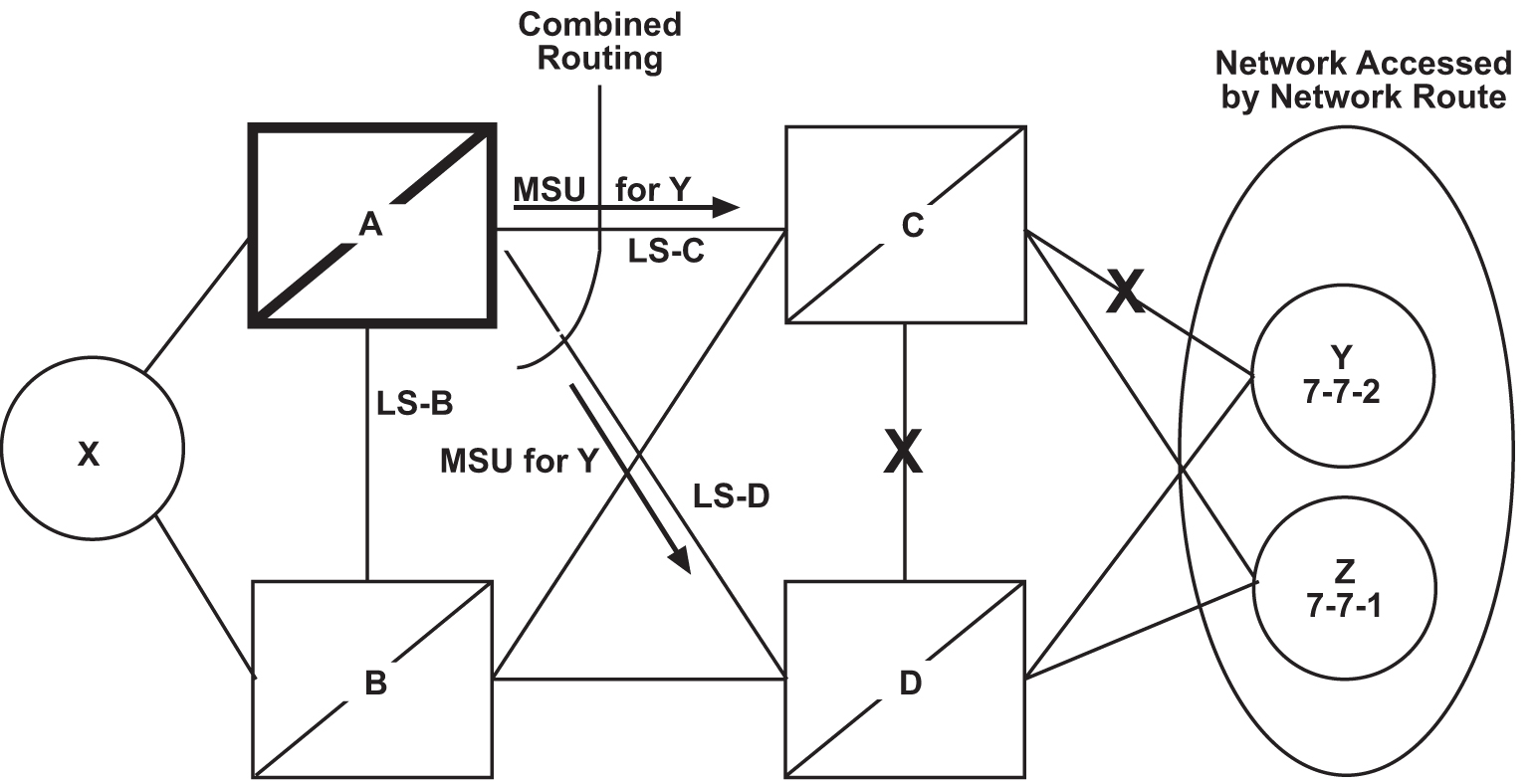
In the example in Figure 2-28, linksets LS-C and LS-D form a combined route to network route 7-*-*. Because 7-*-* is a network route, the EAGLE always considers the non-adjacent status of the routes to be allowed. In the example shown, the EAGLE routes traffic destined to 7-7-1 over LS-C and LS-D. The EAGLE ignores TFPs concerning 7-7-1 or TCPs concerning 7-7-*.
Point Code Availability
A point code that is accessed by a network route entry is considered available if there is any linkset in the routeset that is available for traffic.
Local Link Congestion
This feature has no impact on the generation of TFC messages. A TFC is generated concerning point code X-Y-Z, even if X-Y-Z is routed using a network route entry.
Remote Congestion
Because the EAGLE has global title capabilities, it is possible for the EAGLE to receive a TFC concerning a point code that is accessed by a network route entry. Network route entries are not affected by TFC messages.
Broadcast Transfer Messages
The EAGLE does not broadcast TFx messages for network route entries.
Response Method Transfer Messages
The EAGLE sends response method TFx messages for network routes as follows:
- Prohibited Network Routes
If the EAGLE receives an MSU that is accessed by a network route entry, and that network route is Prohibited, the EAGLE sends a response method TFP or TCP message, as follows:
- If there is a full point code defined in the same cluster as the MSU (for example, 8-*-* and 8-1-1 are defined in the EAGLE's routing table, and MSU is destined for 8-1-2), the EAGLE sends a TFP with concerned point code set to the MSU's DPC.
- Otherwise, the EAGLE sends a TCP with concerned point code set to the cluster of the MSU's DPC.
The EAGLE sends response method TCPs or TFPs at a rate of one TCP or TFP per signaling link during the level 3 T8 timer period for each network route.
For example, in Figure 2-28, the network route for 7-*-* becomes Prohibited due to the failure of LS-B, LS-C, and LS-D. When the EAGLE receives an MSU from X destined for 7-7-1, the EAGLE sends a response method TCP concerning 7-7-*. When the EAGLE receives an MSU from X destined for 7-8-2, the EAGLE sends a response method TCP concerning 7-8-*.
- System Detects Danger of Circular Routing
If the EAGLE receives an MSU that is accessed by a network route entry, and the EAGLE detects danger of circular routing, the EAGLE sends a response method TFP or TCP message, as follows:
- If there is a full point code defined in the same cluster as the MSU (for example, 8-*-* and 8-1-1 are defined in the EAGLE's routing table, and the MSU is destined for 8-1-2), the EAGLE sends a TFP with concerned point code set to the MSU's DPC.
- Otherwise, the EAGLE sends a TCP with concerned point code set to the cluster of the MSU's DPC.
The EAGLE sends response method TCPs at a rate of one TCP per signaling link during the level 3 T8 timer period for each network route.
For example, in Figure 2-28, all linksets are available. If the EAGLE receives an MSU from node C destined for 7-7-1, the EAGLE detects danger of circular routing, and sends a response method TCP concerning 7-7-*. The EAGLE also discards the MSU.
- Restricted Network Routes
If the EAGLE receives an MSU that is accessed by a network route entry, and that network route is Restricted, the EAGLE sends a one-time response method TFR or TCR message, as follows:
- If there is a full point code defined in the same cluster as the MSU (for example, 8-*-* and 8-1-1 are defined in the EAGLE's routing table, and MSU is destined for 8-1-2), the EAGLE sends a TFR with concerned point code set to the MSU's DPC.
- Otherwise, the EAGLE sends a TCR with concerned point code set to the cluster of the MSU's DPC.
For example, in Figure 2-28, the network route for 7-*-* becomes Restricted due to the failure of LS-C and LS-D. When the EAGLE receives an MSU from X destined for 7-7-1, the EAGLE sends a response method TCR concerning 7-7-*, then routes the MSU over LS-B. When the EAGLE next receives an MSU from X destined for 7-8-2, the EAGLE does not send a response, and routes the MSU over LS-B.
Reception of Transfer Messages
The EAGLE does not apply received transfer messages to a network route.
For example, in Figure 2-28, if the EAGLE receives a TFP concerning 7-7-1, it has no effect on the routing status of 7-*-*. The EAGLE continues to send MSUs destined to 7-*-*, including MSUs destined to 7-7-1, on LS-C.
As another example, if the EAGLE receives a TCP concerning 7-8-*, it has no effect on the routing status of 7-*-*. The EAGLE continues to send MSUs destined to 7-*-*, including MSUs destined to 7-8-2, on LS-C.
Reception of an RSx Message
If a routeset test (RSP or RSR) is received, a full point code reply (TFx) is generated. The responses to RSP/RSR have been changed according to Table 2-13. Note that the searching hierarchy applies.
Table 2-13 Reception of an RSx Message
| Concerned Point Code is: | Result |
|---|---|
|
Found by a full point code match |
No change to existing rules. |
|
Found by a cluster match |
No change to existing rules. |
|
Found by a network match |
Send a TFx message based on the current routeset status.
Otherwise:
|
|
Not found |
No change to existing rules. Send a TFP. |
Reception of an RCx Message
If a routeset cluster test (RCP or RCR) is received, a cluster reply (TCx) is generated. The responses to RCP/RCR have been changed according to Table 2-14. Note that the searching hierarchy applies.
Table 2-14 Reception of an RCx Message
| Concerned Point Code is: | Result |
|---|---|
|
Found by a cluster match |
No change to existing rules. |
|
Found by a network match |
Send a TCx message based on the current routeset status.
Otherwise:
|
|
Not found |
No change to existing rules. Send a TCP. |
Administration
The network routing feature must be on, before a network routing point code can be provisioned in the database. This can be verified with the entry NRT = on in the output of the rtrv-feat command. If the network routing feature is not on, NRT = off, it must be turned on with the chg-feat command using the nrt=on parameter. Once the network routing feature is on, the network routing point code can be provisioned in the database like any other destination point code. Routes can then be assigned to the network routing point code like any other destination point code. For more information on provisioning network routing point codes, see the Adding a Network Routing Point Code procedure.
Note:
Once the network routing feature is turned on using thechg-feat command, it cannot be turned off. When using the network routing feature, limited network management is provided for point codes not covered by full point code routing, cluster routing, or nested cluster routing.
The network routing feature must be purchased before you turn this feature on with the chg-feat command. If you are not sure if you have purchased the network routing feature, contact your Oracle Sales Representative or Account Representative.
2.20 Adding a Network Routing Point Code
This procedure is used to add a destination point code to the database, using the ent-dstn command.
To change the attributes of an existing network routing point code, perform the Changing a Destination Point Code procedure.
To remove a network routing point code from the database, perform the Removing a Destination Point Code procedure.
The ent-dstn command uses these parameters.
:dpc/dpca – The destination point code being added to the database
Note:
See Point Code Formats for a definition of the point code types that are used on the EAGLE. Alias point codes (aliasi/aliasn/aliasn24) and secondary point codes (spc/spca) cannot be specified for a network routing point code. An ANSIprivate point code must be a full point code.
:clli – The Common Language Location Identifier assigned to this point code.
:domain – The network in which the destination entity or node exists, SS7.
The network routing point code must be in the SS7 domain (domain=ss7) and can only be an ANSI point code. ITU point codes cannot be specified as network routing point codes.
:nprst - NM bits reset. This parameter specifies whether the NM bits in an ITU IAM message should be set to 00. This parameter has two values.
off- Do not set NM bits to 00 in an ITU IAM message if thenptypeoption value in thertrv-tifoptsoutput isnm.on- Set the NM bits to 00 in an ITU IAM message if thenptypeoption value in thertrv-tifoptsoutput isnm.The default value for this parameter is
off.
:rcause - Release cause. This parameter specifies the condition that triggers the sending of a Release message. This parameter has these values.
- 0 - 127
none- use the values specified for thercausenpandrcausepfxparameters in thertrv-tifoptsoutput.The default value for this parameter is
none.If the
rlcopcparameter value in thertrv-tipoptsoutput is on and a value of 0-127 is specified for thercauseparameter, then thercauseparameter value overrides the values specified for thercausenpandrcausepfxparameters in thertrv-tifoptsoutput.
:splitiam - This parameter specifies how and when to split an ITU IAM message into one IAM message and one SAM message. This parameter has these values.
- 15-31 - The maximum number of CdPN digits allowed in the IAM message before the splitting occurs. The remaining digits, up to a total of 32, are encoded in the SAM message.
none- the value specified for thesplitiamparameter in thertrv-tifoptsoutput is used to determine when to split the IAM message.The default value for this parameter is
none.
nprst or rcause parameters, the TIF Number Portability feature, part number 893018901, must be enabled. To specify the splitiam parameter, at least one of these features must be enabled.
- TIF Number Portability - part number 893018901
- TIF SCS Forwarding - part number 893022201
- TIF Simple Number Substitution - part number 893024001
- TIF Additional Subscriber Data - part number 893024501
- TIF Generic Routing Number - part number 893025501
The status of these features is shown in the
rtrv-ctrl-featoutput. Perform the procedures in TIF User's Guide to enable these features.
:sccpmsgcnv - The sccpmsgcnv parameter controls SCCP UDT(S)/XUDT(S) message conversion for the specified destination. This parameter can be specified only if the XUDT UDT Conversion feature is enabled and turned on. The rtrv-ctrl-feat output shows the status of the XUDT UDT Conversion feature. If the XUDT UDT Conversion feature is not enabled or turned on, perform the "Activating the XUDT UDT Conversion Feature" procedure in Database Administration - GTT User's Guide to enable and turn on the XUDT UDT Conversion feature. This parameter contains these values.
- none - SCCP UDT(S)/XUDT(S) message conversion is not required on messages for the destination. This value is the default value for this parameter.
- udt2xudt - All UDT(S) messages for the destination are converted to XUDT(S) messages.
- xudt2udt - All non-segmented XUDT(S) messages for the destination are converted to UDT(S) messages. Segmented XUDT(S) messages for the destination are not converted to UDT(S ) messages.
- sxudt2udt - All segmented and non-segmented XUDT(S) messages for the destination are converted to UDT(S) messages.
ncai |
spc |
elei |
bei |
ipgwapc |
ppc |
prx |
The ent-dstn command also contains the homescp and homesmsc parameters. The values for these parameters are yes and no. The value no is the default value for these parameters. The value yes for these parameters cannot be specified for a network routing point code. To specify the value yes for these parameters, perform the Adding a Destination Point Code or Changing a Destination Point Code procedures.
The value of the clli parameter cannot be in the DPC table and cannot match the CLLI of the EAGLE. Verify this by entering the rtrv-dstn and the rtrv-sid commands, shown in 1 and 2. If the value of the clli parameter matches any CLLI values in either of these outputs, choose another value for the clli parameter that does not match any CLLIs shown in either of these command outputs.
To enter the dpc/dpca parameter with the ent-dstn command, a point code must be defined in the PCA field of the self ID of the EAGLE. Verify this with the rtrv-sid command.
If no value is shown in the PCA field in the rtrv-sid command output, the self-identification of the EAGLE must be updated with an ANSI point code. Go to Changing the Self-Identification of the EAGLE procedure to change the self-identification of the EAGLE.
Note:
To enter a network routing point code with the network indicator values 1 through 5, thepctype parameter value of the chg-sid command must be set to other. If you attempt to add a network routing point code with the network indicator values 1 through 5 and the pctype parameter value is ansi, the ent-dstn command will be rejected with this error message.
E2169 Cmd Rej: Point code out of range
Destination point codes must be unique in the database.
The actual number of destination point codes that can be configured in the database is set by the mtpdpcq parameter of the chg-stpopts command, and is shown in the MTPDPCQ field in the rtrv-stpopts command output.
If the 5000 Routes feature is not on, and 6000, 7000, 8000, or 10,000 routesets are not enabled, a maximum of 2000 destination point codes can be configured in the database.
If the 5000 Routes feature is on, and 6000, 7000, 8000, or 10,000 routesets are not enabled, a maximum of 5000 destination point codes can be configured in the database.
If 6000 routesets are enabled, a maximum of 6000 destination point codes can be configured in the database.
If 7000 routesets are enabled, a maximum of 7000 destination point codes can be configured in the database.
If 8000 routesets are enabled, a maximum of 8000 destination point codes can be configured in the database.
If 10,000 routesets are enabled, a maximum of 10,000 destination point codes can be configured in the database.
Note:
For more information on the destination point code quantities, refer to the Changing the DPC Quantity procedure.The examples in this procedure are used to add the network routing point code 007-*-* to the database.
Canceling the RTRV-DSTN Command
Because the rtrv-dstn command used in this procedure can output information for a long period of time, the rtrv-dstn command can be canceled and the output to the terminal stopped. There are three ways that the rtrv-dstn command can be canceled:
-
Press the
F9function key on the keyboard at the terminal where thertrv-dstncommand was entered. -
Enter the
canc-cmdwithout thetrmparameter at the terminal where thertrv-dstncommand was entered. -
Enter the
canc-cmd:trm=<xx>, where<xx>is the terminal where thertrv-dstncommand was entered, from another terminal other than the terminal where thertrv-dstncommand was entered. To enter thecanc-cmd:trm=<xx>command, the terminal must allow Security Administration commands to be entered from it and the user must be allowed to enter Security Administration commands. The terminal’s permissions can be verified with thertrv-secu-trmcommand. The user’s permissions can be verified with thertrv-userorrtrv-secu-usercommands.
For more information about the canc-cmd command, refer to Commands User's Guide.
Figure 2-29 Adding a Network Routing Point Code
2.21 Adding a Destination Point Code
This procedure is used to add a destination point code to the database, using the ent-dstn command.
The ent-dstn command uses these parameters:
:dpc/dpca/dpci/dpcn/dpcn24 – The destination point code being added to the database
:aliasa/aliasi/aliasn/aliasn24 – The alternate destination point code. Two optional alias addresses can be defined.
:ppc/ppca/ppci/ppcn/ppcn24 – The proxy point code that is assigned to the destination point code.
Note:
See Point Code Formats for a definition of the point code types that are used on the EAGLE and for a definition of the different formats that can be used for ITU national point codes. A private point code cannot be used as an alias point code.:clli – The Common Language Location Identifier assigned to this point code
:domain – The network in which the destination entity or node exists, SS7.
:ipgwapc – IP Gateway Adjacent Point Code indicator. Specify ipgwapc=yes to provide SS7 linkset definition compatibility for gateway connections to IP-SCPs. The default is ipgwapc=no.
:bei – Broadcast exception indicator that indicates whether transfer-prohibited (TFP) messages will be broadcast from this node. The bei=yes parameter means TFPs will not be broadcast. The bei=no parameter means TFPs will be broadcast.
:spc/spca/spci/spcn/spcn24 – The secondary point code as defined by the ent-spc command. The secondary point code allows the EAGLE to use another point code in addition to the one defined by the dpc, dpca, dpci, dpcn, or dpcn24 parameters of the ent-dstn command for SS7 routing purposes. Refer to the Multiple Point Code Support section for more information on secondary point codes. A private point code cannot be used as a secondary point code.
:prx – This parameter specified whether or not the destination point code is proxy point code. This parameter has two values, yes or no. If the prx parameter value is yes, the destination point code is a proxy point code. If the prx parameter value is no, the destination point code is not a proxy point code.
The ppc and prx parameters can be specified only if a quantity of proxy point codes is enabled. Proxy point code quantities are enabled in groups of 10. The enabled quantity of proxy point codes is shown in the rtrv-ctrl-feat output. If no proxy point code quantity is shown in the rtrv-ctrl-feat output, or the proxy point code quantity needs to be increased, up to a maximum quantity of 100 proxy point codes, perform the Changing the Proxy Point Code Quantity procedure.
The ppc parameter assigns a proxy point code to a destination point code. The proxy point code value must be provisioned in the database. The destination point code must be a full point code, in the SS7 domain, and cannot be a private point code. The destination point code cannot have the ipgwapc=yes parameter value assigned. The destination point code and proxy point code must be the same network type. For example, if the destination point code is an ANSI point code, the proxy point code must be an ANSI point code. If the destination point code and proxy point code are 14-bit ITU-N point codes with a group code, the group code values for both the destination point code and the proxy point code must be the same. The spc and ppc parameters cannot be specified together in the same ent-dstn command line.
The prx parameter specifies whether or not the destination point code specified with the ent-dstn command is a proxy point code. The destination point code value must be a full point code, in the SS7 domain, and cannot be a private point code. The destination point code value cannot have the ipgwapc=yes parameter value assigned.
:nprst - NM bits reset. This parameter specifies whether the NM bits in an ITU IAM message should be set to 00. This parameter has two values.
off- Do not set NM bits to 00 in an ITU IAM message if thenptypeoption value in thertrv-tifoptsoutput isnm.on- Set the NM bits to 00 in an ITU IAM message if thenptypeoption value in thertrv-tifoptsoutput isnm.The default value for this parameter is
off.
:rcause - Release cause. This parameter specifies the condition that triggers the sending of a Release message. This parameter has these values.
- 0 - 127
none- use the values specified for thercausenpandrcausepfxparameters in thertrv-tifoptsoutput.The default value for this parameter is
none.If the
rlcopcparameter value in thertrv-tipoptsoutput is on and a value of 0-127 is specified for thercauseparameter, then thercauseparameter value overrides the values specified for thercausenpandrcausepfxparameters in thertrv-tifoptsoutput.
:splitiam - This parameter specifies how and when to split an ITU IAM message into one IAM message and one SAM message. This parameter has these values.
- 15-31 - The maximum number of CdPN digits allowed in the IAM message before the splitting occurs. The remaining digits, up to a total of 32, are encoded in the SAM message.
none- the value specified for thesplitiamparameter in thertrv-tifoptsoutput is used to determine when to split the IAM message.The default value for this parameter is
none.
nprst or rcause parameters, the TIF Number Portability feature, part number 893018901, must be enabled. To specify the splitiam parameter, at least one of these features must be enabled.
- TIF Number Portability - part number 893018901
- TIF SCS Forwarding - part number 893022201
- TIF Simple Number Substitution - part number 893024001
- TIF Additional Subscriber Data - part number 893024501
- TIF Generic Routing Number - part number 893025501
The status of these features is shown in the
rtrv-ctrl-featoutput. Perform the procedures in TIF User's Guide to enable these features.
:homescp - This parameter specifies whether the destination point code should be considered a home SCP when performing SCCP processing for messages that have no global title address digits (the global title indicator (GTI) is set to zero). This parameter cannot be specified for a cluster point code or a network routing point code. These are the values for this parameter.
- yes- the specified DPC is considered a home SCP.
- no - the specified DPC is not considered a home SCP. This is the default value.
:homesmsc - This parameter specifies whether the destination point code (DPC) should be considered a home SMSC when performing SCCP processing for messages that have no global title address digits (the global title indicator (GTI) is set to zero). This parameter cannot be specified for a cluster point code or a network routing point code. These are the values for this parameter.
- yes- the specified DPC is considered a home SMSC.
- no - the specified DPC is not considered a home SMSC. This is the default value.
:sccpmsgcnv - The sccpmsgcnv parameter controls SCCP UDT(S)/XUDT(S) message conversion for the specified destination. This parameter can be specified only if the XUDT UDT Conversion feature is enabled and turned on. The rtrv-ctrl-feat output shows the status of the XUDT UDT Conversion feature. If the XUDT UDT Conversion feature is not enabled or turned on, perform the "Activating the XUDT UDT Conversion Feature" procedure in Database Administration - GTT User's Guide to enable and turn on the XUDT UDT Conversion feature. This parameter contains these values.
- none - SCCP UDT(S)/XUDT(S) message conversion is not required on messages for the destination. This value is the default value for this parameter.
- udt2xudt - All UDT(S) messages for the destination are converted to XUDT(S) messages.
- xudt2udt - All non-segmented XUDT(S) messages for the destination are converted to UDT(S) messages. Segmented XUDT(S) messages for the destination are not converted to UDT(S ) messages.
- sxudt2udt - All segmented and non-segmented XUDT(S) messages for the destination are converted to UDT(S) messages.
The elei and ncai parameters cannot be specified in this procedure. To use these parameters to provision a destination point code, perform the Adding a Cluster Point Code procedure.
Secondary point codes must be a full point code. A secondary point code can only be assigned to a full point code. The network type of the secondary point code must match the network type of the DPC. The secondary point code used in this procedure must be configured in the database with the ent-spc command. The secondary point codes are shown in the SPCA, SPC-I, SPC-N, and SPC-N24 fields of the rtrv-spc command output. If the desired secondary point code is not shown in the output of the rtrv-spc command, perform the Adding a Secondary Point Code procedure to configure the desired point code as a secondary point code.
The value of the clli parameter cannot be in the DPC table and cannot match the CLLI of the EAGLE. Verify this by entering the rtrv-dstn and the rtrv-sid commands, shown in steps 1 and 5 of the procedure that follows. If the value of the clli parameter matches any CLLI values in either of these outputs, choose another value for the clli parameter that does not match any CLLIs shown in either of these command outputs.
To enter point codes of any network type (ANSI, ITU-I, 14-bit ITU-N, or 24-bit ITU-N) into the database with the ent-dstn command, the self ID of the EAGLE must be defined for these networks. Verify this with the rtrv-sid command.
If a point code value is shown in the PCA column of the rtrv-sid command, then ANSI point codes can be specified with the ent-dstn command.
If a point code value is shown in the PCI column of the output of the rtrv-sid command, then ITU-I point codes can be specified with the ent-dstn command. The PCI column of the rtrv-sid output can contain spare and non-spare point code values. To provision ITU-I non-spare point codes in this procedure, the rtrv-sid output must contain an ITU-I non-spare point code in the PCI column. To provision ITU-I spare point codes in this procedure, the rtrv-sid output must contain an ITU-I spare point code in the PCI column.
If a point code value is shown in the PCN column of the output of the rtrv-sid command, then 14-bit ITU-N point codes can be specified with the ent-dstn command. The PCN column of the rtrv-sid output can contain spare and non-spare point code values. To provision 14-bit ITU-N non-spare point codes in this procedure, the rtrv-sid output must contain a 14-bit ITU-N non-spare point code in the PCN column. To provision 14-bit ITU-N spare point codes in this procedure, the rtrv-sid output must contain a 14-bit ITU-N spare point code in the PCN column.
If a point code value is shown in the PCN24 column of the output of the rtrv-sid command, then 24-bit ITU-N point codes can be specified with the ent-dstn command.
If no values are shown in the PCA, PCI, PCN, or PCN24 columns in the rtrv-sid command output, the self-identification of the EAGLE must be updated with an ANSI point code, ITU international point code, 14-bit ITU national point code, or a 24-bit ITU national point code. Perform the Adding a Point Code to the Self-Identification of the EAGLE procedure to add the necessary point codes to the self-identification of the EAGLE.
Note:
The EAGLE can contain 14-bit ITU national point codes or 24-bit ITU national point codes, but both at the same time.Private point codes cannot be specified in the self-identification of the EAGLE, therefore, private point codes can be added as long as the self identification of the EAGLE contains a point code with the same network type as the private point code being added in this procedure. The ITU National and International Spare Point Code Support feature does not have to be enabled to add a private point code. A proxy point code cannot be used as a value when specifying a private point code.
The type of alias point code that can be provisioned with the ent-dstn command is dependent on the type of DPC that is being provisioned. Table 2-15 shows the DPC and alias point type combinations that can be used with the ent-dstn command.
Table 2-15 Destination Point Code Type and Alias Point Code Type Combinations
| DPC Type | Alias Point Code Type (See Notes 1 - 4) | Alias Point Code Type (See Notes 1 - 4) | DPC TYPE | Alias Point Code Type (See Notes 1 - 4) | Alias Point Code Type (See Notes 1 - 4) |
|---|---|---|---|---|---|
| ANSI | no alias specified | no alias specified | ITU-I | no alias specified | no alias specified |
| ITU-I | no alias specified | ANSI | no alias specified | ||
| ITU-I | ITU-N | ANSI | ITU-N | ||
| ITU-I | ITU-N Spare | ANSI | ITU-N Spare | ||
| ITU-I | ITU-N24 | ANSI | ITU-N24 | ||
| ITU-I Spare | no alias specified | ITU-I Spare | no alias specified | ||
| ITU-I Spare | ITU-N | ITU-I Spare | ITU-N | ||
| ITU-I Spare | ITU-N Spare | ITU-I Spare | ITU-N Spare | ||
| ITU-I Spare | ITU-N24 | ITU-I Spare | ITU-N24 | ||
| ITU-N | no alias specified | ITU-N | no alias specified | ||
| ITU-N Spare | no alias specified | ITU-N (Note 6) | ITU-N Spare (Note 6) | ||
| ITU-N24 | no alias specified | ITU-N Spare | no alias specified | ||
| ITU-I Spare | no alias specified | no alias specified | ITU-N24 | no alias specified | |
| ANSI | no alias specified | ITU-N | no alias specified | no alias specified | |
| ANSI | ITU-N | ANSI | no alias specified | ||
| ANSI | ITU-N Spare | ANSI | ITU-I | ||
| ANSI | ITU-N24 | ANSI | ITU-I Spare | ||
| ITU-I | no alias specified | ITU-I | no alias specified | ||
| ITU-I | ITU-N | ITU-I (Note 5) | ITU-I Spare (Note 5) | ||
| ITU-I | ITU-N Spare | ITU-I Spare | no alias specified | ||
| ITU-I | ITU-N24 | ITU-N Spare | no alias specified | ||
| ITU-N | no alias specified | ITU-N Spare | ITU-I | ||
| ITU-N (Note 6) | ITU-N Spare (Note 6) | ITU-N Spare | ITU-I Spare | ||
| ITU-N Spare | no alias specified | ITU-N24 | no alias specified | no alias specified | |
| ITU-N24 | no alias specified | ANSI | no alias specified | ||
| ITU-N Spare | no alias specified | no alias specified | ANSI | ITU-I | |
| ANSI | no alias specified | ANSI | ITU-I Spare | ||
| ANSI | ITU-I | ITU-I | no alias specified | ||
| ANSI | ITU-I Spare | ITU-I Spare | no alias specified | ||
| ITU-I | no alias specified | ||||
| ITU-I (Note 5) | ITU-I Spare (Note 5) | ||||
| ITU-I Spare | no alias specified | ||||
| ITU-N | no alias specified | ||||
| ITU-N | ITU-I | ||||
| ITU-N | ITU-I Spare | ||||
Notes:
|
|||||
Alias point codes can only be specified for full point code entries, and must be full point codes.
ANSI alias point codes cannot be a member of a cluster point code that is already in the database. A point code is a member of a cluster point code if it has the same network identifier (NI) and network cluster (NC) values as the cluster point code.
Table 2-16 Maximum Alias Point Code Quantities
| Feature Status | Maximum Alias Point Code Quantity |
|---|---|
| The 5000 Routes feature is off and 6000, 7000, 8000, or 10,000 routesets are not enabled | 12000 |
| The 5000 Routes feature is on and 6000, 7000, 8000, or 10,000 routesets are not enabled | 12000 |
| 6000 routesets are enabled | 12000 |
| 7000 routesets are enabled | 8000 |
| 8000 routesets are enabled | 8000 |
| 10,000 routesets are enabled | 10000 |
Destination point codes and alias point codes must be unique in the database. A point code can be defined as a true destination point code, an alias point code, the self ID of the EAGLE, or the capability point code of the EAGLE. The self IDs and capability point codes of the EAGLE can be verified with the rtrv-sid command.
If the PCTYPE field of the rtrv-sid command output contains the entry ANSI, and the network value of the destination point code specified by the ent-dstn command is from 0 to 5, the cluster value of that point code must be from 1 to 255. If the network value of that point code is from 6 to 255, the cluster value of that point code must be from 0 to 255.
The actual number of destination point codes that can be configured in the database is set by the mtpdpcq parameter of the chg-stpopts command, and is shown in the MTPDPCQ field in the rtrv-stpopts command output.
If the 5000 Routes feature is not on, and 6000, 7000, 8000, or 10,000 routesets are not enabled, a maximum of 2000 destination point codes can be configured in the database.
If the 5000 Routes feature is on, and 6000, 7000, 8000, or 10,000 routesets are not enabled, a maximum of 5000 destination point codes can be configured in the database.
If 6000 routesets are enabled, a maximum of 6000 destination point codes can be configured in the database.
If 7000 routesets are enabled, a maximum of 7000 destination point codes can be configured in the database.
If 8000 routesets are enabled, a maximum of 8000 destination point codes can be configured in the database.
If 10,000 routesets are enabled, a maximum of 10,000 destination point codes can be configured in the database.
Note:
For more information on the destination point code quantities, refer to the Changing the DPC Quantity procedure.If ITU-N point codes are specified with the ent-dstn command, the format of the point code values must match the format shown in the NPCFMTI field of the rtrv-stpopts command output. For more information, refer to the 14-Bit ITU National Point Code Formats section.
Canceling the RTRV-DSTN Command
Because the rtrv-dstn command used in this procedure can output information for a long period of time, the rtrv-dstn command can be canceled and the output to the terminal stopped. There are three ways that the rtrv-dstn command can be canceled:
- Press the
F9function key on the keyboard at the terminal where thertrv-dstncommand was entered - Enter the
canc-cmdwithout thetrmparameter at the terminal where thertrv-dstncommand was entered - Enter the
canc-cmd:trm=<xx>, where<xx>is the terminal where thertrv-dstncommand was entered, from another terminal other than the terminal where thertrv-dstncommand was entered. To enter thecanc-cmd:trm=<xx>command, the terminal must allow Security Administration commands to be entered from it and the user must be allowed to enter Security Administration commands. The terminal’s permissions can be verified with thertrv-secu-trmcommand. The user’s permissions can be verified with thertrv-userorrtrv-secu-usercommands.
For more information about the canc-cmd command, refer to Commands User's Guide.
Figure 2-30 Adding a Destination Point Code
2.22 Removing a Destination Point Code
This procedure is used to remove a destination point code from the database, using the dlt-dstn command.
The dlt-dstn command uses this parameter:
:dpc/dpca/dpci/dpcn/dpcn24 – The destination point code being removed from the database
Note:
See Point Code Formats for a definition of the point code types that are used on the EAGLE and for a definition of the different formats that can be used for ITU national point codes.The destination point code to be removed must exist in the database, but cannot be assigned to any routes. Enter the rtrv-rte command to see if the destination point code to be removed is assigned to any routes. If the destination point code is assigned to any routes, perform Removing a Route to remove these routes.
The destination point code cannot be defined as an adjacent point code for a linkset. Enter the rtrv-ls to see if the destination point code to be removed is defined as an adjacent point code for a linkset. If the destination point code is defined as an adjacent point code for a linkset, perform Removing a Linkset Containing SS7 Signaling Links.
- The destination point code is a member of a cluster point code. This is shown by entering the
rtrv-dstncommand and specifying the destination point code with three asterisks (***) for the network cluster member value of the destination point code instead of the actual network cluster value of the destination point code. - The
NCAIvalue of the cluster point code isno. This is shown by entering thertrv-dstncommand and specifying the cluster point code. - The destination point code is the DPC of an exception route. This is shown by entering the
rtrv-rtxcommand and specifying the destination point code that is being removed.
If the destination point code meets these conditions, perform the Removing a Route Exception Entry procedure to remove the exception route entries that reference the DPC that is being removed.
The destination point code cannot be in the mated relay node (MRN) table. Verify this by entering the rtrv-mrn command, specifying the destination point code being removed from the database. If the destination point code is shown in the rtrv-mrn command output, remove the point code from the MRN table, by performing the Removing an MRN Group or MRN Group Entry" procedure in Database Administration - GTT User's Guide.
The destination point code cannot be in the mated application (MAP) table. Verify this by entering the rtrv-map command, specifying the destination point code being removed from the database. If the destination point code is shown in the rtrv-map command output, remove the point code from the MAP table, by performing the Removing a Mated Application" procedure in Database Administration - GTT User's Guide.
The destination point code cannot be defined as an end office internal point code. Verify this by entering the rtrv-rmt-appl command. If the destination point code is shown in the rtrv-rmt-appl command output, perform the “Removing an End Node Internal Point Code” procedure in Database Administration - IP7 User's Guide to remove the internal point code.
If the point code being removed in this procedure is a proxy point code, the proxy point code cannot be removed if the proxy point code is assigned to a destination point code or assigned to a linkset. Proxy point codes are shown in the rtrv-dstn:dpc=<DPC value> output with the entry PRX=yes. To verify if the proxy point code is assigned to a destination point code, enter the rtrv-dstn command with the ppc parameter equal to the proxy point code value. This will display all the destination point codes that reference the proxy point code. These destination point codes must be removed before the proxy point code can be removed.
To verify if the proxy point code is assigned to a linkset, enter the rtrv-ls command with the ppc parameter equal to the proxy point code value. This will display all the linksets that reference the proxy point code. These linksets must be removed before the proxy point code can be removed.
Canceling the RTRV-DSTN and RTRV-LS Commands
Because the rtrv-dstn and rtrv-ls commands used in this procedure can output information for a long period of time, the rtrv-dstn and rtrv-ls commands can be canceled and the output to the terminal stopped. There are three ways that the rtrv-dstn and rtrv-ls commands can be canceled:
- Press the
F9function key on the keyboard at the terminal where thertrv-dstnorrtrv-lscommand was entered - Enter the
canc-cmdwithout thetrmparameter at the terminal where thertrv-dstnorrtrv-lscommand was entered - Enter the
canc-cmd:trm=<xx>, where<xx>is the terminal where thertrv-dstnorrtrv-lscommand was entered, from another terminal other than the terminal where thertrv-dstnorrtrv-lscommand was entered. To enter thecanc-cmd:trm=<xx>command, the terminal must allow Security Administration commands to be entered from it and the user must be allowed to enter Security Administration commands. The terminal’s permissions can be verified with thertrv-secu-trmcommand. The user’s permissions can be verified with thertrv-userorrtrv-secu-usercommands.
For more information about the canc-cmd command, go to Commands User's Guide.
Figure 2-31 Removing a Destination Point Code
2.23 Changing a Destination Point Code
This procedure is used to change the attributes of a full destination point code in the database, using the chg-dstn command.
To change the attributes of a cluster point code, go to the Changing the Attributes of a Cluster Point Code procedure.
This procedure cannot be used to change a true point code (dpc/dpca/dpci/dpcn/dpcn24), or a proxy point code value assigned to a DPC. To change a true point code or a proxy point code value assigned to a DPC, the destination point code must be removed, then re-entered. Perform the Removing a Destination Point Code procedure to remove the point code from the database. To add the new point code, perform one of these procedures:
- Cluster point code – Adding a Cluster Point Code
- Network routing point code – Adding a Network Routing Point Code
- All other point codes – Adding a Destination Point Code
Note:
To add a proxy point code, the point code cannot be a cluster point code or a network routing point code.The destination point code to be changed must be in the database.
The chg-dstn command uses these parameters:
:dpc/dpca/dpci/dpcn/dpcn24 – The destination point code in the database being changed.
:aliasa/aliasi/aliasn/aliasn24 – The alternate destination point code. Two optional alias addresses can be defined.
Note:
See Point Code Formats for a definition of the point code types that are used on the EAGLE and for a definition of the different formats that can be used for ITU national point codes. A private point code cannot be used as an alias point code.:clli – The Common Language Location Identifier assigned to this point code
:bei – Broadcast exception indicator that indicates whether transfer-prohibited (TFP) messages will be broadcast from this node. The bei=yes parameter means TFPs will not be broadcast. The bei=no parameter means TFPs will be broadcast.
:spc/spca/spci/spcn/spcn24 – The secondary point code as defined by the ent-spc command. The secondary point code allows the EAGLE to use another point code in addition to the one defined by the dpc, dpca, dpci, dpcn, or dpcn24 parameters of the chg-dstn command for SS7 routing purposes. See the Multiple Point Code Support section for more information on secondary point codes. A private point code cannot be used as a secondary point code.
:prx – This parameter specified whether or not the destination point code is proxy point code. This parameter has two values, yes or no. If the prx parameter value is yes, the destination point code is a proxy point code. If the prx parameter value is no, the destination point code is not a proxy point code. To specify the prx=yes parameter, the destination point code value must be a full point code, in the SS7 domain, and cannot be a private point code. The destination point code value cannot have the ipgwapc=yes parameter value assigned.
To specify the prx=no parameter, the proxy point code cannot be assigned to a destination point code or assigned to a linkset. Proxy point codes are shown in the rtrv-dstn:dpc=<DPC being changed> output with the entry PRX=yes. To verify if the proxy point code is assigned to a destination point code, enter the rtrv-dstn command with the ppc parameter equal to the proxy point code value. This will display all the destination point codes that reference the proxy point code. These destination point codes must be removed before the prx=no parameter can be specified..
To verify if the proxy point code is assigned to a linkset, enter the rtrv-ls command with the ppc parameter equal to the proxy point code value. This will display all the linksets that reference the proxy point code. These linksets must be removed before the proxy point code can be removed.
:nprst - NM bits reset. This parameter specifies whether the NM bits in an ITU IAM message should be set to 00. This parameter has two values.
off- Do not set NM bits to 00 in an ITU IAM message if thenptypeoption value in thertrv-tifoptsoutput isnm.on- Set the NM bits to 00 in an ITU IAM message if thenptypeoption value in thertrv-tifoptsoutput isnm.The default value for this parameter is
off.
:rcause - Release cause. This parameter specifies the condition that triggers the sending of a Release message. This parameter has these values.
- 0 - 127
none- use the values specified for thercausenpandrcausepfxparameters in thertrv-tifoptsoutput.The default value for this parameter is
none.If the
rlcopcparameter value in thertrv-tipoptsoutput is on and a value of 0-127 is specified for thercauseparameter, then thercauseparameter value overrides the values specified for thercausenpandrcausepfxparameters in thertrv-tifoptsoutput.
:splitiam - This parameter specifies how and when to split an ITU IAM message into one IAM message and one SAM message. This parameter has these values.
- 15-31 - The maximum number of CdPN digits allowed in the IAM message before the splitting occurs. The remaining digits, up to a total of 32, are encoded in the SAM message.
none- the value specified for thesplitiamparameter in thertrv-tifoptsoutput is used to determine when to split the IAM message.The default value for this parameter is
none.
nprst or rcause parameters, the TIF Number Portability feature, part number 893018901, must be enabled. To specify the splitiam parameter, at least one of these features must be enabled.
- TIF Number Portability - part number 893018901
- TIF SCS Forwarding - part number 893022201
- TIF Simple Number Substitution - part number 893024001
- TIF Additional Subscriber Data - part number 893024501
- TIF Generic Routing Number - part number 893025501
The status of these features is shown in the
rtrv-ctrl-featoutput. Perform the procedures in TIF - User's Guide to enable these features.
:homescp - This parameter specifies whether the destination point code should be considered a home SCP when performing SCCP processing for messages that have no global title address digits (the global title indicator (GTI) is set to zero). This parameter cannot be specified for a cluster point code or a network routing point code. These are the values for this parameter.
- yes- the specified DPC is considered a home SCP.
- no - the specified DPC is not considered a home SCP.
:homesmsc - This parameter specifies whether the destination point code (DPC) should be considered a home SMSC when performing SCCP processing for messages that have no global title address digits (the global title indicator (GTI) is set to zero). This parameter cannot be specified for a cluster point code or a network routing point code. These are the values for this parameter.
- yes- the specified DPC is considered a home SMSC.
- no - the specified DPC is not considered a home SMSC.
:sccpmsgcnv - The sccpmsgcnv parameter controls SCCP UDT(S)/XUDT(S) message conversion for the specified destination. This parameter can be specified only if the XUDT UDT Conversion feature is enabled and turned on. The rtrv-ctrl-feat output shows the status of the XUDT UDT Conversion feature. If the XUDT UDT Conversion feature is not enabled or turned on, perform the "Activating the XUDT UDT Conversion Feature" procedure in Database Administration - GTT User's Guide to enable and turn on the XUDT UDT Conversion feature. This parameter contains these values.
- none - SCCP UDT(S)/XUDT(S) message conversion is not required on messages for the destination.
- udt2xudt - All UDT(S) messages for the destination are converted to XUDT(S) messages.
- xudt2udt - All non-segmented XUDT(S) messages for the destination are converted to UDT(S) messages. Segmented XUDT(S) messages for the destination are not converted to UDT(S ) messages.
- sxudt2udt - All segmented and non-segmented XUDT(S) messages for the destination are converted to UDT(S) messages.
The elei and ncai parameters cannot be specified in this procedure. To use these parameters to provision a destination point code, perform the Changing the Attributes of a Cluster Point Code procedure.
Secondary point codes must be a full point code. A secondary point code can only be assigned to a full point code in the SS7 domain. Secondary point codes cannot be assigned to DPCs that have proxy point codes assigned to them. The same secondary point code value cannot be assigned to DPCs and to linksets The network type of the secondary point code must match the network type of the destination point code. The secondary point code used in this procedure must be configured in the database with the ent-spc command. The secondary point codes are shown in the SPCA, SPC-I, SPC-N, and SPC-N24 fields of the rtrv-spc command output. If the desired secondary point code is not shown in the output of the rtrv-spc command, perform the Adding a Secondary Point Code procedure to configure the desired point code as a secondary point code.
If a secondary point code is assigned to the destination point code, the group code of the 14-bit ITU-N destination point code must match the group code of the secondary point code. Otherwise, the group code of the destination point code must match the group code assigned to the EAGLE’s true 14-bit ITU-N point code, shown in the PCN field of the rtrv-sid output.
The value none for the spca, spci, spcn, or spcn24 parameters removes the assignment of the current secondary point code and leaves the destination point code without a secondary point code.
The value of the clli parameter cannot be in the destination point code table and cannot match the CLLI of the EAGLE. Verify this by entering the rtrv-dstn and the rtrv-sid commands. If the value of the clli parameter matches any CLLI values in either of these outputs, choose another value for the clli parameter that does not match any CLLIs shown in either of these command outputs.
To enter point codes of any network type (ANSI, ITU-I, or ITU-N - 14-bit or 24-bit) into the database with the chg-dstn command, the self ID of the EAGLE must be defined for these networks. Verify this with the rtrv-sid command.
If a point code value is shown in the PCA field of the rtrv-sid command, then ANSI point codes can be specified with the chg-dstn command.
If a point code value is shown in the PCI field of the output of the rtrv-sid command, then ITU-I point codes can be specified with the chg-dstn command. The PCI column of the rtrv-sid output can contain spare and non-spare point code values. To provision ITU-I non-spare point codes in this procedure, the rtrv-sid output must contain an ITU-I non-spare point code in the PCI column. To provision ITU-I spare point codes in this procedure, the rtrv-sid output must contain an ITU-I spare point code in the PCI column.
If a point code value is shown in the PCN field of the output of the rtrv-sid command, then 14-bit ITU-N point codes can be specified with the chg-dstn command. The PCN column of the rtrv-sid output can contain spare and non-spare point code values. To provision 14-bit ITU-N non-spare point codes in this procedure, the rtrv-sid output must contain a 14-bit ITU-N non-spare point code in the PCN column. To provision 14-bit ITU-N spare point codes in this procedure, the rtrv-sid output must contain a 14-bit ITU-N spare point code in the PCN column.
If a point code value is shown in the PCN24 field of the output of the rtrv-sid command, then 24-bit ITU-N point codes can be specified with the chg-dstn command.
If no values are shown in the PCA, PCI, PCN, or PCN24 fields in the rtrv-sid command output, the self-identification of the EAGLE must be updated with an ANSI point code, ITU international point code or a 14-bit ITU national point code. Perform the Changing the Self-Identification of the EAGLE procedure to change the self-identification of the EAGLE.
Note:
The EAGLE can contain 14-bit ITU national point codes or 24-bit ITU national point codes, but both at the same time.Private point codes cannot be specified in the self-identification of the EAGLE, therefore, private point codes can be added as long as the self identification of the EAGLE contains a point code with the same network type as the private point code being added in this procedure. The ITU National and International Spare Point Code Support feature does not have to be enabled to add a private point code.
The type of alias point code that can be provisioned with the chg-dstn command is dependent on the type of DPC that is being provisioned. Table 2-17 shows the DPC and alias point type combinations that can be used with the chg-dstn command.
Table 2-17 Destination Point Code Type and Alias Point Code Type Combinations
| DPC Type | Alias Point Code Type (See Notes 1 - 7) | Alias Point Code Type (See Notes 1 - 7) | DPC TYPE | Alias Point Code Type (See Notes 1 - 7) | Alias Point Code Type (See Notes 1 - 7) |
|---|---|---|---|---|---|
| ANSI | no alias specified | no alias specified | ITU-I | no alias specified | no alias specified |
| ITU-I | no alias specified | ANSI | no alias specified | ||
| ITU-I | ITU-N | ANSI | ITU-N | ||
| ITU-I | ITU-N Spare | ANSI | ITU-N Spare | ||
| ITU-I | ITU-N24 | ANSI | ITU-N24 | ||
| ITU-I Spare | no alias specified | ITU-I Spare | no alias specified | ||
| ITU-I Spare | ITU-N | ITU-I Spare | ITU-N | ||
| ITU-I Spare | ITU-N Spare | ITU-I Spare | ITU-N Spare | ||
| ITU-I Spare | ITU-N24 | ITU-I Spare | ITU-N24 | ||
| ITU-N | no alias specified | ITU-N | no alias specified | ||
| ITU-N Spare | no alias specified | ITU-N (Note 9) | ITU-N Spare (Note 9) | ||
| ITU-N24 | no alias specified | ITU-N Spare | no alias specified | ||
| ITU-I Spare | no alias specified | no alias specified | ITU-N24 | no alias specified | |
| ANSI | no alias specified | ITU-N | no alias specified | no alias specified | |
| ANSI | ITU-N | ANSI | no alias specified | ||
| ANSI | ITU-N Spare | ANSI | ITU-I | ||
| ANSI | ITU-N24 | ANSI | ITU-I Spare | ||
| ITU-I | no alias specified | ITU-I | no alias specified | ||
| ITU-I | ITU-N | ITU-I (Note 8) | ITU-I Spare (Note 8) | ||
| ITU-I | ITU-N Spare | ITU-I Spare | no alias specified | ||
| ITU-I | ITU-N24 | ITU-N Spare | no alias specified | ||
| ITU-N | no alias specified | ITU-N Spare | ITU-I | ||
| ITU-N (Note 9) | ITU-N Spare (Note 9) | ITU-N Spare | ITU-I Spare | ||
| ITU-N Spare | no alias specified | ITU-N24 | no alias specified | no alias specified | |
| ITU-N24 | no alias specified | ANSI | no alias specified | ||
| ITU-N Spare | no alias specified | no alias specified | ANSI | ITU-I | |
| ANSI | no alias specified | ANSI | ITU-I Spare | ||
| ANSI | ITU-I | ITU-I | no alias specified | ||
| ANSI | ITU-I Spare | ITU-I Spare | no alias specified | ||
| ITU-I | no alias specified | ||||
| ITU-I (Note 8) | ITU-I Spare (Note 8) | ||||
| ITU-I Spare | no alias specified | ||||
| ITU-N | no alias specified | ||||
| ITU-N | ITU-I | ||||
| ITU-N | ITU-I Spare | ||||
Notes:
|
|||||
Alias point codes can only be specified for full point code entries and must be full point codes.
Destination point codes and alias point codes must be unique in the database. A point code cannot be defined as a true destination point code and an alias point code.
Table 2-18 Maximum Alias Point Code Quantities
| Feature Status | Maximum Alias Point Code Quantity |
|---|---|
| The 5000 Routes feature is off and 6000, 7000, 8000, or 10,000 routesets are not enabled | 12000 |
| The 5000 Routes feature is on and 6000, 7000, 8000, or 10,000 routesets are not enabled | 12000 |
| 6000 routesets are enabled | 12000 |
| 7000 routesets are enabled | 8000 |
| 8000 routesets are enabled | 8000 |
| 10,000 routesets are enabled | 10000 |
If either the dpcn or aliasn parameters are specified with the chg-dstn command, the format of the 14-bit ITU-N point code values must match the format shown in the NPCFMTI field of the rtrv-stpopts command output. For more information, refer to the 14-Bit ITU National Point Code Formats section.
Canceling the RTRV-DSTN Command
Because the rtrv-dstn command used in this procedure can output information for a long period of time, the rtrv-dstn command can be canceled and the output to the terminal stopped. There are three ways that the rtrv-dstn command can be canceled:
- Press the
F9function key on the keyboard at the terminal where thertrv-dstncommand was entered - Enter the
canc-cmdwithout thetrmparameter at the terminal where thertrv-dstncommand was entered - Enter the
canc-cmd:trm=<xx>, where<xx>is the terminal where thertrv-dstncommand was entered, from another terminal other than the terminal where thertrv-dstncommand was entered. To enter thecanc-cmd:trm=<xx>command, the terminal must allow Security Administration commands to be entered from it and the user must be allowed to enter Security Administration commands. The terminal’s permissions can be verified with thertrv-secu-trmcommand. The user’s permissions can be verified with thertrv-userorrtrv-secu-usercommands.
For more information about the canc-cmd command, refer to Commands User's Guide.
Figure 2-32 Changing a Destination Point Code
2.24 Changing the Group Code Assigned to a 14-Bit ITU National Point Code
This procedure is used to change the group code that is assigned to a 14-bit ITU national point code. The 14-bit ITU national point code to be changed must be in the database.
To change a group code assigned to a ITU national point code, a duplicate point code with the new group code must be configured in the database with a route, linkset, and signaling link to the new destination. Then the 14-bit ITU national point code with the old group code with its route can be removed from the database.
The chg-dstn command cannot be used to change the group code assigned to 14-bit ITU national point codes.
The examples in this procedure are used to remove the group code assigned to ITU national destination point code 7-9-10-1-aa to 7-9-10-1-de. The format of the 14-bit ITU national point codes used in these examples is 4-4-4-2.
Canceling the RTRV-DSTN and RTRV-RTE Commands
Because the rtrv-dstn and rtrv-rte commands used in this procedure can output information for a long period of time, the rtrv-dstn and rtrv-rte commands can be canceled and the output to the terminal stopped. There are three ways that the rtrv-dstn and rtrv-rte commands can be canceled:
- Press the
F9function key on the keyboard at the terminal where thertrv-dstnorrtrv-rtecommand was entered - Enter the
canc-cmdwithout thetrmparameter at the terminal where thertrv-dstnorrtrv-rtecommand was entered - Enter the
canc-cmd:trm=<xx>, where<xx>is the terminal where thertrv-dstnorrtrv-rtecommand was entered, from another terminal other than the terminal where thertrv-dstnorrtrv-rtecommand was entered. To enter thecanc-cmd:trm=<xx>command, the terminal must allow Security Administration commands to be entered from it and the user must be allowed to enter Security Administration commands. The terminal’s permissions can be verified with thertrv-secu-trmcommand. The user’s permissions can be verified with thertrv-userorrtrv-secu-usercommands.
For more information about the canc-cmd command, refer to Commands User's Guide.
Figure 2-33 Changing the Group Code Assigned to a 14-Bit ITU National Point Code