2 Integrating EAGLE Application B Card (E5-APP-B) into the LSMS Network
This chapter provides guidance for integrating the LSMS into your internal and external local area network (LAN) or wide area network (WAN).
Overview
This chapter provides guidance for integrating the LSMS into your internal and external local area network (LAN) or wide area network (WAN).
This chapter describes how to provide preliminary planning guidance, help you assemble the data for the LSMS Site Survey, and provide source material for installation and upgrade procedures.
Understanding the LSMS Network
LSMS provides a series of network connections to enable it to interact with NPACs, EMSs, and local and remote consoles. The following sets of network connections can be made to your network:
-
E5-APP-B
LSMS blade server that is EAGLE Extension Shelf compatible.
-
Depending on your network configuration, a Gigabit Ethernet interface typically connects to an external WAN. This interface provides connectivity to one or more remote NPAC sites. These connections are shown going to the NPACWAN in Figure 2-1.
-
Depending on your network configuration, a Gigabit Ethernet interface typically connects to your site’s secure WAN. This interface provides connectivity to the customer’s EMS (EAGLE) sites. These connections are shown going to the EMSWAN in Figure 2-1.
-
Depending on your network configuration, a Gigabit Ethernet interface typically connects to your site’s internal LAN or secure WAN. The internal LAN is also known as the customer LAN, and the application network operates on it. This interface provides connectivity for workstations that use the IP User Interface. These connections are shown going to the Application WAN in Figure 2-1.
-
OOBM (Only on Tekserver)
Depending on your network configuration, a Gigabit Ethernet interface typically connects to your site’s internal LAN or secure WAN. This interface provides connectivity to the T1100 AS console port via the OOBM card.
-
Internal Networks
Depending on your network configuration, a Gigabit Ethernet interface typically connects to your site’s internal LAN or secure WAN. These interfaces cross connect the two servers for use with heartbeats and database replication.
Understanding the Primary Protocols
The following primary protocols are used in LSMS network connections:
-
The Q.3 protocol employs standard TCP/IP at OSI layers 1 through 3, and the OSI protocol at levels 4 through 7. LSMS uses a TMN tool kit and Marben protocol stack to implement the OSI protocols for these interfaces. This protocol stack does not use the TSEL parameter in the LSMS configuration. This protocol is used for connections with NPACs.
Note:
The copying of both the runtime NETECH license at path/usr/local/netech/etc/licenseand the Marben OSI license at path/usr/TKLC/osi/conf/licenseis required. -
The standard TCP/IP stack is used for:
-
Application network
-
Connections with ELAPs
-
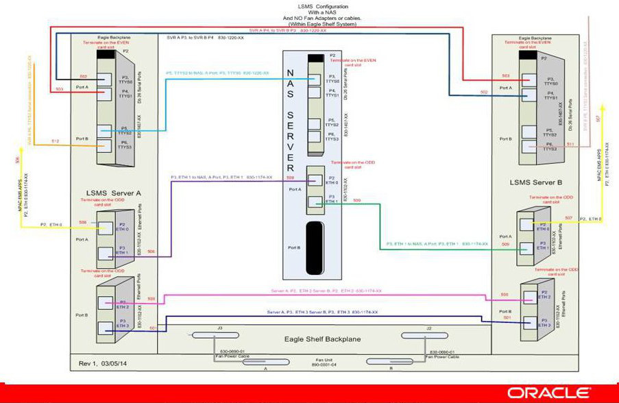
Figure 2-1 shows the LSMS network Single Subnet backplane connections.
Figure 2-1 LSMS Configuration: Single Subnet Backplane Connections
Understanding the Multiple Network Interfaces
Each external interface is connected to each LSMS server. Each interface has a redundant interface that can be used if there is a system failure. These multiple interfaces:
-
Provide network security by establishing a clear boundary between the various external networks
-
Provide dedicated bandwidth for each interface, reducing the risk of congestion while allowing growth
-
Aid in troubleshooting and isolating errors
Understanding the Physical Port Assignments
The number of active Ethernet connections for a server depends on which network configuration is used to implement the redundant connectivity between the servers and with external entities.
-
Single subnet: each server requires four Ethernet connections and five IP addresses (one for the VIP address and two for the cloud)
The following figures and tables show E5-APP-B configuration. Figure 2-2 shows how to connect cables to the server in a single subnet configuration and Table 2-1 defines the physical port assignments.
Note:
A single subnet network configuration is recommended due to the ease of configuration and maintenance.Figure 2-2 Physical Port Assignments - E5-APP-B Single Subnet Configuration
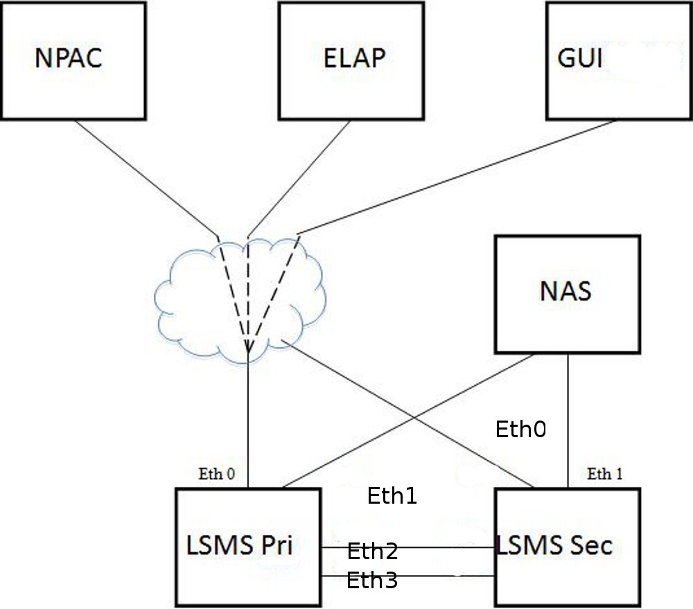
Table 2-1 Physical Port Assignments - E5-APP-B Single Subnet Configuration
| LAN Interface | Connections | Speed |
|---|---|---|
| Eth0 | NPAC, ELAP, GUI, EMS, SSH | Gigabit Ethernet |
| Eth1 | Direct connect to NAS | Gigabit Ethernet |
| Eth2 | Direct connect to Mate for Heartbeat and MySQL replication | Gigabit Ethernet |
| Eth3 | Direct connect to Mate for Heartbeat and MySQL replication | Gigabit Ethernet |
The NAS is directly connected with the LSMS in the single subnet configuration. The NAS is configured using dhcp.
Eth0 is used to configure the NPAC, ELAP and APP (GUI/SSH).
-
Segmented network: each server requires eight Ethernet connections and nine IP addresses (one for the VIP address and six for the clouds)
Note:
There are more switch/router ports required to enable the segmented configuration, which the customer is required to provide. The local switch needs one port for each LSMS Primary, Secondary and NAS. For E5-APP-B, Eth1 is no longer physically connected to the NAS. Eth1 must connect to a local switch for proper NAS performance. The dedicated switch ports must be set to 1Gbps.Figure 2-3 shows how to connect cables to the server in a segmented configuration and Table 2-2 defines the physical port assignments.
Figure 2-3 Physical Port Assignments - E5-APP-B Segmented Configuration

Table 2-2 Physical Port Assignments - E5-APP-B Segmented Configuration
| LAN Interface | Connections | Speed |
|---|---|---|
| Eth0 | NPAC | Gigabit Ethernet |
| Eth1 | NAS, ELAP, GUI, EMS, SSH, Query Server, SNMP | Gigabit Ethernet |
| Eth2 | Direct connect to Mate for Heartbeat and MySQL replication | Gigabit Ethernet |
| Eth3 | Direct connect to Mate for Heartbeat and MySQL replication | Gigabit Ethernet |
Figure 2-4 LSMS Configuration: Segmented Configuration
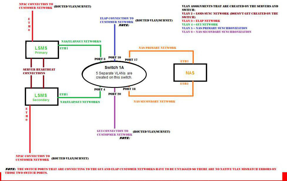
The NAS is connected to Eth1 via switch. The NAS is configured using dhcp.
The two aliases of Eth1 are Eth1:0 and Eth1:1, respectively.
Eth1:0 is used to configure APP (GUI/SSH via switch).
Eth1:1 is used to configure ELAP via switch.
Assigning the IP Addresses
For installation of the LSMS, you must provide a minimum of three IP addresses to configure the LSMS to single subnet configuration:
-
In a single subnet configuration, a minimum of 3 IP addresses (see Table 2-5.
-
In a segmented configuration, a minimum of 9 IP addresses (see Table 2-6.
The servers share the VIP address. During a switchover, the LSMS HA switches the VIP address to the newly active server.
Handling the VIP Address during a Switchover
The Virtual IP (VIP) address is constantly associated with whichever server is active. The VIP is used for the active server on the Application network only.
Note:
All query servers must use the Application Network so that they can continue to replicate from the active server when switchover occurs.For more information about switchover, refer to Alarms and Maintenance Guide.
Table 2-3 compares how IP and MAC addresses are used in LSMS 9.0 or later and how they were used in previous releases of LSMS.
Table 2-3 Comparing LSMS 7.0 and 9.0 or later Addresses
| Address | LSMS 7.0 | LSMS 9.0 or later | ||
|---|---|---|---|---|
| Configuration required | How treated during switchover | Configuration required | How treated during switchover | |
|
Server MAC addresses |
Changed ha.env file to configure FirstWatch with server MAC addresses |
When switchover occurred, both the MAC addresses and the IP addresses were swapped between the primary server and the secondary server |
(Not used for switchover) |
|
|
IP address for primary server |
Changed ha.env file to configure FirstWatch with primary server IP address |
When switchover occurred, both the MAC addresses and the IP addresses were swapped between the primary server and the secondary server |
Use |
Assignment not changed (only the VIP address is switched over automatically to the new active server) |
|
IP address for secondary server |
Needed to configure FirstWatch with secondary server IP address |
When switchover occurred, both the MAC addresses and the IP addresses were swapped between the primary server and the secondary server |
Use |
Assignment not changed (only the VIP address is switched over automatically to the new active server) |
|
VIP (Virtual IP) address |
N/A |
N/A |
Use |
During switchover, VIP address is assigned to whichever server is active |
|
NOTE: The server in the upper position in the frame is called server A and, by default, is assigned the hostname lsmspri; the other server is called server B and is assigned the hostname lsmssec. These hostnames can be changed. In LSMS 9.0 or later, lsmspri and lsmssec are merely hostnames; they do not indicate a primary/secondary relationship. In LSMS 9.0 or later, the servers are peers. |
||||
Assigning IP Addresses in LSMS 9.0 or later
The VIP address is another address, in addition to the IP addresses for each specific server. If customers desire to use the same IP addresses that they used for previous releases of LSMS, it is recommended that they configure the LSMS to use the IP address that was previously assigned to the primary server as the new VIP address, and assign the new IP address to one of the servers, as shown in Table 2-4.
Using the IP address that was previously used for the primary server as the VIP address prevents customers from having to reconfigure various applications that were configured to use that IP address.
Table 2-4 Reusing Existing Server IP Addresses
| IP Address | In LSMS 7.0, was assigned to: | In LSMS 9.0 or later, assign to: |
|---|---|---|
|
IP Address 1 |
lsmspri server |
VIP |
|
IP Address 2 |
lsmssec server |
Either server |
|
IP Address 3 |
N/A |
Either server |
Simplified Configuration Procedures
Most configuration procedures are performed by Oracle Communications employees. Details of the configuration tasks they perform are described later in this chapter. After initial configuration has been performed, customers may choose to use the lsmsmgr text interface to change some configuration details, such as changing NTP (Network Time Protocol) servers.
Query Server Configuration
Because the LSMS now uses database replication instead of shared storage systems, a variety of changes have been made to ensure that query servers always connect to the active server and that any database replication is performed properly. Some query server configuration procedures have changed.
For detailed information about how to configure the query server, refer to Configuring the Query Server.
Netmask and Broadcast
The LSMS netmask defaults to a mask matching the address class assigned to each interface. In the event of a class “C” interface, the default broadcast address is the interface address ORed with a mask of x000000FF. For example, an IP address of 192.168.89.40 would have a broadcast address of 192.168.89.255.
IP Address Provisioning
Table 2-5 and Table 2-6 details the addresses required for LSMS and their assignment to interfaces. In the following tables, interfaces marked with a dagger (†) are generally visible outside the immediate LSMS area (the customer-provided network), that is, typically they pass through routers and firewalls.
Table 2-5 IP Address Provisioning (Single Subnet Configuration)
| IP Address | Protocol | Speed | Assigned to |
|---|---|---|---|
|
Active NPAC, EMS, and Application Network † |
Q.3 or TCP/IP |
Gigabit Ethernet |
Active LSMS Server |
|
Inactive NPAC, EMS, and Application Network |
TCP/IP |
Gigabit Ethernet |
Inactive LSMS Server |
Table 2-6 IP Address Provisioning (Segmented Configuration)
| IP Address | Protocol | Speed | Assigned to |
|---|---|---|---|
|
Active NPAC network † |
Q.3 |
Gigabit Ethernet |
Active LSMS server |
|
Active NAS, EMS network † and Application Network |
Q.3 or TCP/IP |
Gigabit Ethernet |
Active LSMS server |
|
Direct connect to Mate for Heartbeat and MySQL replication |
TCP/IP |
Gigabit Ethernet |
Active LSMS server |
|
Inactive NPAC network † |
TCP/IP |
Gigabit Ethernet |
Active LSMS server |
|
Inactive EMS † and Application Network |
TCP/IP |
Gigabit Ethernet |
Active LSMS server |
|
Inactive Application Network |
TCP/IP |
Gigabit Ethernet |
Active LSMS server |
Adding Additional Routes
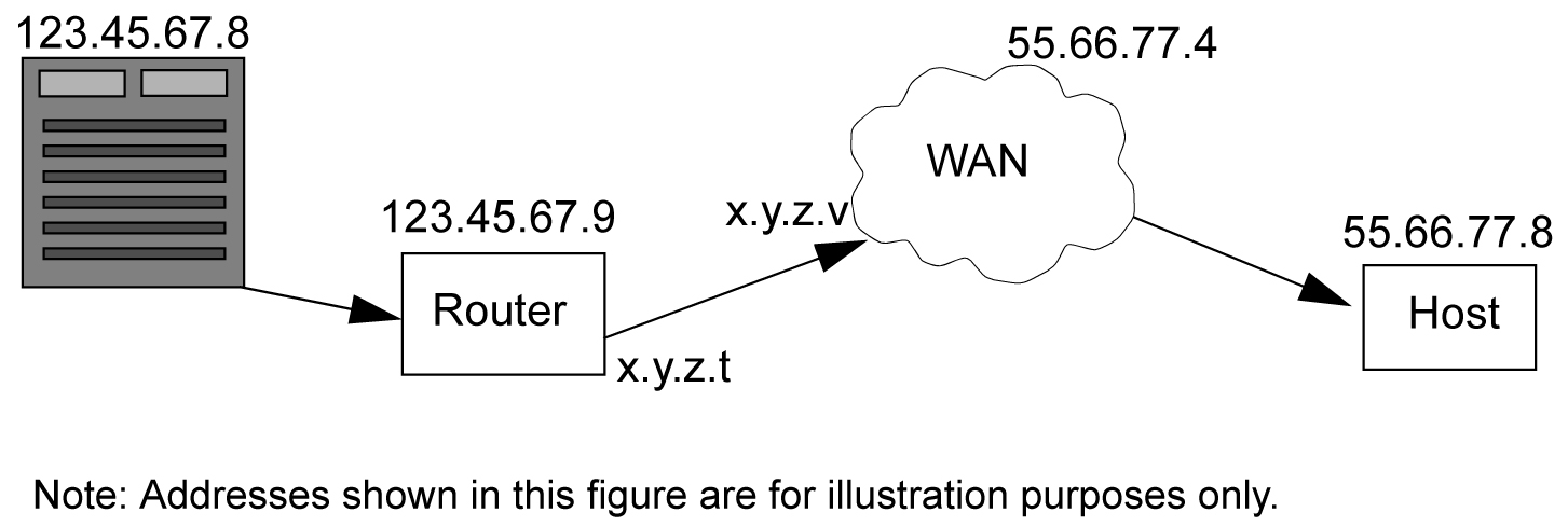
If you use a multiport router or an Ethernet switch in your network, it is your responsibility to ensure that the network connection receiving packets for the destination end (typically the NPAC or EMS networks) has an address on the same subnet as each interface. Figure 2-5 illustrates the routing methodology.
Figure 2-5 LSMS Interface Routing in a Segmented Configuration
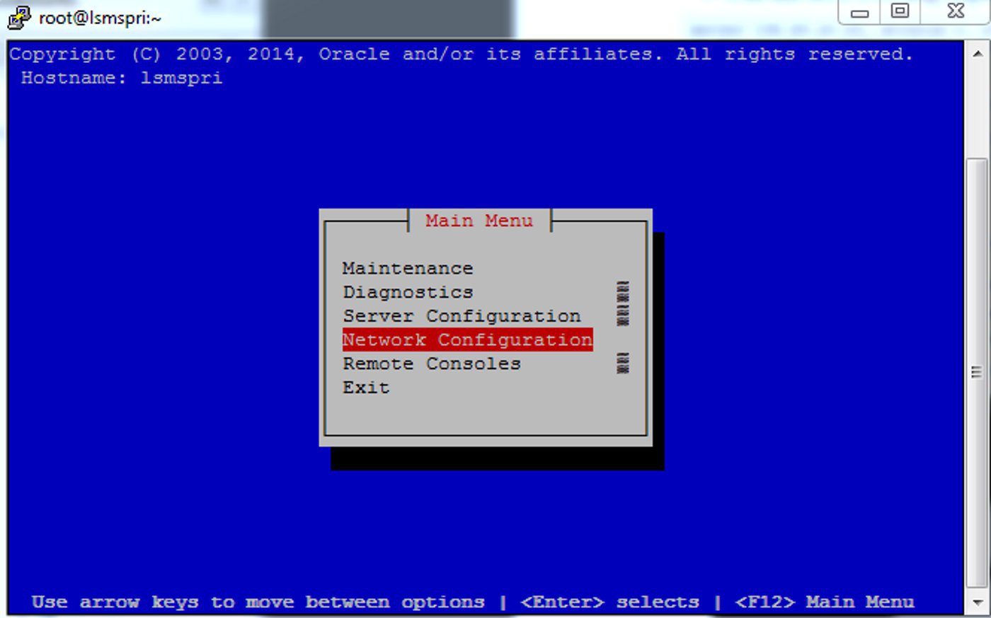
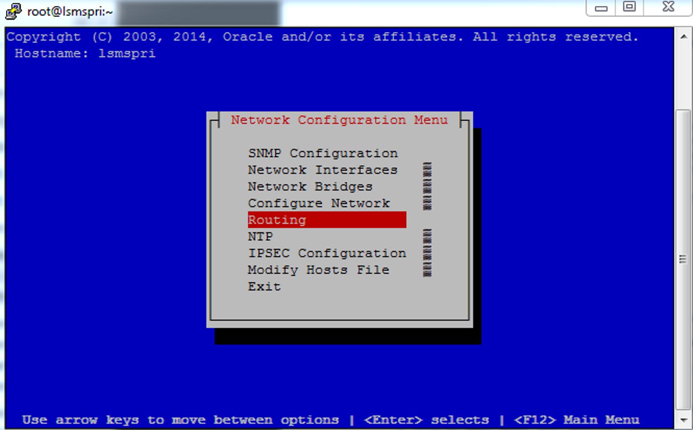
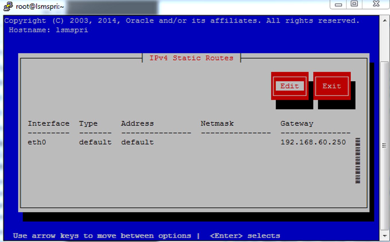
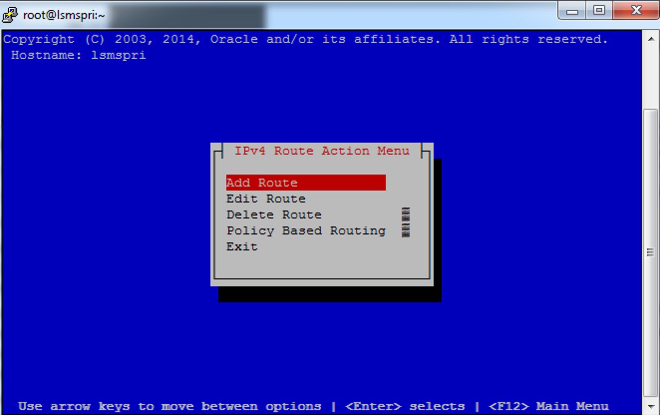
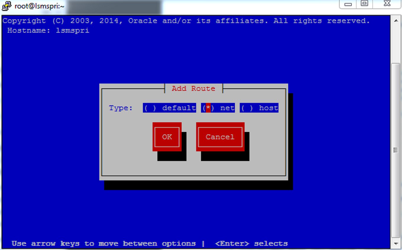
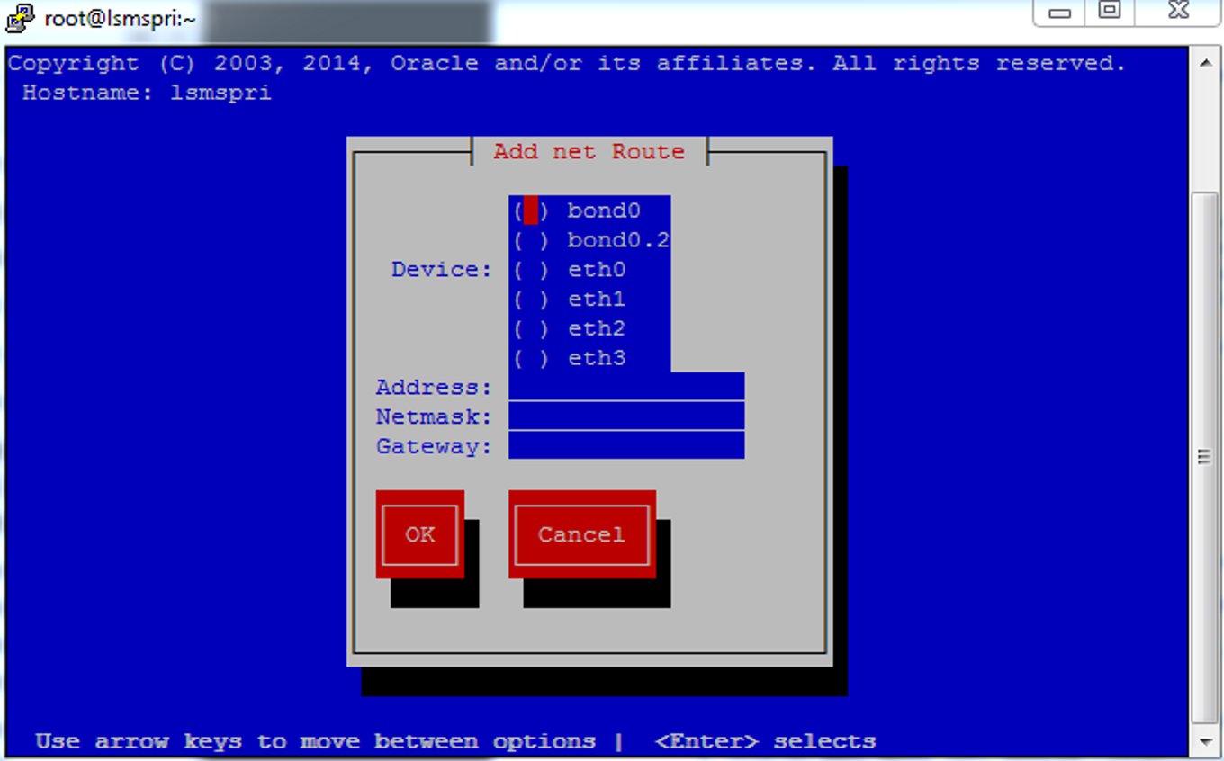
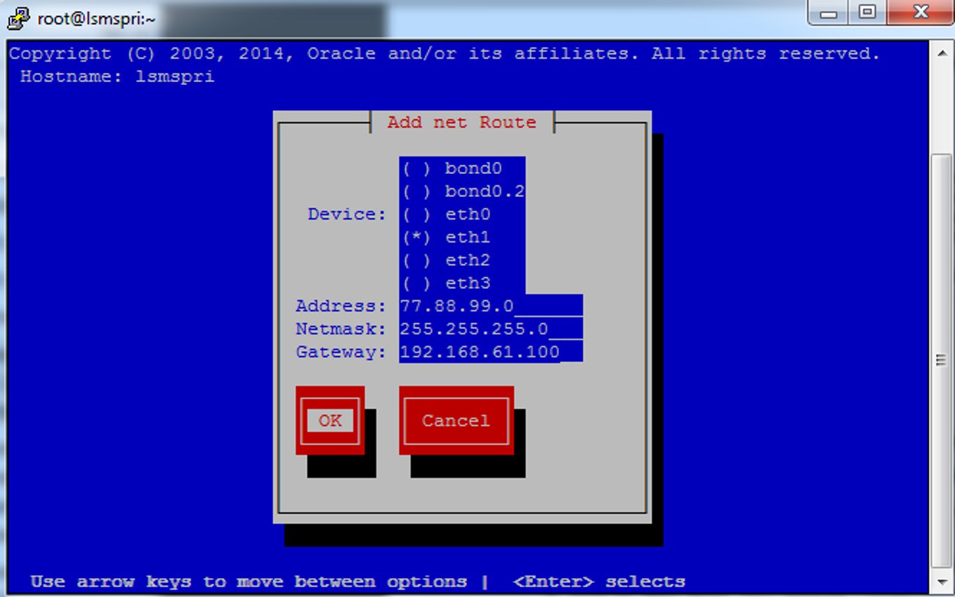
For more routes for your network, use this procedure to define additional routes.
Understanding Firewall and Router Filtering
Firewall protocol filtering for the various interfaces is defined in the following table:
Table 2-7 LSMS External Ports and Their Use
| Interface | TCP/IP Port | Use | Inbound | Outbound |
|---|---|---|---|---|
|
To NPAC 100BASE-TX (eth0) |
102 |
Yes |
Yes |
|
|
20 |
FTP data1 |
No |
Yes |
|
|
21 |
FTP1 |
No |
Yes |
|
|
22 |
TCP (ssh, sftp) |
Yes2 |
Yes |
|
|
To EMS 100BASE-TX (eth0) |
1030 |
TCP |
Yes |
Yes |
|
22 |
TCP (ssh, sftp) |
Yes4 |
Yes |
|
|
123 |
NTP |
Yes |
Yes |
|
|
80 |
Apache |
Yes |
No |
|
|
8001 |
suEXEC |
Yes |
No |
|
|
443 |
HTTPS/Apache |
Yes |
No |
|
|
8473 |
GUI Server |
Yes |
Yes |
|
|
1030 |
LSMS Bulk Download and High Speed Audit |
Yes |
Yes |
|
|
7483 |
LSMS Provisioning Data |
Yes |
Yes |
|
|
9691 |
Watcher Port (diagnostics) |
Yes |
Yes |
|
|
To Application Network 100BASE-TX (eth0) |
123 |
NTP (time synchronization) |
Yes |
Yes |
|
102 |
OSI - TSAP3 |
Yes |
Yes |
|
|
22 |
TCP (ssh, sftp) |
Yes4 |
Yes |
|
|
162 |
SNMP Trap |
No |
Yes |
|
|
N/A |
X Window Packets |
Yes |
Yes |
|
|
20 |
FTP data2 |
No |
Yes |
|
|
21 |
FTP2 |
No |
Yes |
|
|
162 |
SNMP Trap |
No |
Yes |
|
|
7079 |
Web GUI |
Yes |
Yes |
|
|
7080 |
Web GUI |
Yes |
Yes |
|
|
8200 |
Application |
Yes |
Yes |
|
|
To Query Server (only if Query Server Package is enabled) |
3306 |
LSMS Database Replication |
No |
Yes |
| 1FTP data normally is received from the NPAC. The option is left for the LSMS to transfer data with the NPAC and EMS. This assumes the firewall automatically opens the high numbered return port (the default behavior of firewalls such as Firewall-1). If you are using a basic packet filtering router, contact My Oracle Support (MOS)).
2The two-way TCP communication channel endpoints are the port number 22 and the Server spawned random port value. 3OSI transactions on the application network are used only to support Service Assurance. 4The two-way TCP communication channel endpoints are the port number 22 and the Server spawned random port value. Note: For a segmented configuration, eth1 is used for EMS/APP connections. |
||||
Changing Additional Network Information
There are additional changes to the network information that you may wish to define, including:
-
Changing LSMS System IP Addresses - If there are conflicts with defaults of IP addresses assigned to private networks, you can modify the system IP addresses.
-
Modifying a Netmask - If the netmask for a given network is different from the default for that network class (i.e., 255.255.255.0 for a Class C network), you can modify the netmask.
-
Configuring Critical Network Interfaces - Specify any network interface as a critical interface. Whenever the Surveillance feature determines that a critical interface on the active server cannot be reached, the automatic switchover feature switches over to the standby server (for more information, refer to the Alarms and Maintenance Guide).
To make any of these changes to your network information, use the following procedure (the entry of data changes occurs in 6)
