3 Completing Configuration and Starting Connections
This chapter explains how to create and start databases, configure Service Provider contact information, work with key lists, and configure and start NPAC components, EMS components, LSMS components.
Overview
This chapter explains how to create and start databases, configure Service Provider contact information, work with key lists, and configure and start NPAC components, EMS components, LSMS components.
- Midwest
- MidAtlantic
- Northeast
- Southeast
- Southwest
- Western
- WestCoast
- Canada
LSMS can support all eight NPACs simultaneously. The LSMS acts as the interface between one or more NPACs and one or more network elements (NEs). Each NE is accessed through its Element Management System (EMS).
After you have installed the LSMS (for more information, refer to the LSMS Hardware Reference Manual) and integrated it into your network (see Integrating EAGLE Application B Card (E5-APP-B) into the LSMS Network), perform the remaining configuration procedures, as shown in Table 3-1 and Table 3-2.
Completing Configuration
Perform the procedures shown in Table 3-1 in the order shown, depending on whether you are installing LSMS for the first time or adding an NPAC region at a later time. In either case, the last step in Table 3-1 directs you to perform the steps in Table 3-2.
Table 3-1 Recommended Order of Configuration Procedures
| Recommended Order for Initial Installation | Recommended Order for Adding New Region After Installation | Procedures |
|---|---|---|
|
1 (Only if needed) |
1 |
|
|
2 |
(Not needed) |
Log into the LSMS GUI for the first time (see "Starting an LSMS GUI Session" in the Alarms and Maintenance Guide). |
|
3 |
(Not needed) |
Create a service provider entry for the LSMS owner in the LSMS database by performing the procedure “Adding Service Provider Contact Information”. |
|
4 |
(Not needed) |
Select and log in with the SPID you created in the previous step. |
|
5 |
2 (if needed) |
For each additional SPID that you desire to allow access to LSMS data, create a supported service provider entry in the LSMS database by performing the procedure “Adding Service Provider Contact Information”. |
|
6 |
(Not needed) |
Modify the LSMS component by performing the procedure Modifying LSMS Configuration Components. |
|
7 |
(Not needed) |
For each EMS to be supported, create an EMS component by performing the procedure Creating an EMS Configuration Component. |
|
8 |
3 |
For each NPAC, perform the list of procedures described in Table 3-2. |
|
9 |
4 |
If desired, change the default TT/SSN values by performing the procedure “Modifying Default TT/SSN Values”. |
Completing Configuration and Associating with Each NPAC Region
Either as part of initial installation or to add an additional region after the initial installation, perform the procedures in the order shown below once for each NPAC region you need to support.
Table 3-2 Configuring and Associating Each NPAC Region
| Step | Procedure to Perform |
|---|---|
|
1 |
Perform the procedure “Generating a Key List”. |
|
2 |
Select to load the NPAC public key list into the LSMS database by performing the procedure Loading an NPAC Key List. For the Key File field, type the following value in the Key List File field, where
|
|
3 |
Select to load the LSMS private key list into the LSMS database by performing the procedure Loading an LSMS Key List. For the Key File field, type the following value in the Key List File field, where
|
|
4 |
Select to create a secondary NPAC component and enter the information described in “Modifying an NPAC Component”. Ensure that the Activate Region checkbox is empty. For the Component ID field, a value that is one greater than the value entered in the procedure in row 5 is suggested. |
|
5 |
Click the icon that corresponds to this region so that the icon is highlighted, and select to create a primary NPAC component. Enter the information described in “Modifying an NPAC Component”. Ensure that the Activate Region checkbox is filled in. When you click the OK button, the sentry utility will automatically attempt to associate with the NPAC. |
Creating Databases
If you are adding a region to be supported, use the following procedure to create the database for the new region:
Service Provider Contact Information
Use the following procedures to add, modify, view, and delete service provider contact information.
Adding Service Provider Contact Information
To add service provider contact information into the LSMS database, use the following procedure.
- From the LSMS Console window, select .The Create LSMS Service Provider window displays.
Figure 3-1 Configure Service Provider Selection

Figure 3-2 Create LSMS Service Provider Window

- When finished, click OK to apply the changes and return to the LSMS Console window, or Apply to apply the changes and remain in the current window. Click OK in the message window:
Figure 3-3 Create Successful

Modifying Service Provider Contact Information
To modify service provider contact information, use the following procedure.
- From the LSMS Console window, select .
Figure 3-4 Modify LSMS Service Provider Window

- When finished, click OK to apply the changes and return to the LSMS Console window, or Apply to apply the changes and remain in the current window. Click OK in the message window:
Figure 3-5 Modify Successful

Viewing Service Provider Contact Information
To view service provider contact information, use the following procedure.
- From the LSMS Console window, select .The information in this window is read-only and cannot be modified.
Figure 3-6 View LSMS Service Provider Window

Deleting Service Provider Contact Information
To delete service provider contact information, use this procedure.
- From the LSMS Console window, select .
Figure 3-7 Delete LSMS Service Provider Window

- When finished, click OK to apply the changes and return to the LSMS Console window, or Apply to apply the changes and remain in the current window. In either case, the Delete Confirmation window displays.
Figure 3-8 Delete Confirmation Window

LSMS Configuration Components
Use the following procedures to manage LSMS configuration components:
Modifying LSMS Configuration Components
Use the following procedure to create or modify LSMS configuration components.
- From the main menu, select .The Modify LNP System LSMS window displays. In this example, the Primary was selected. The window usually opens with the Component Info tab displayed; if the Component Info tab is not displayed, click its tab to display it.
Figure 3-9 LNP System Menu – Modify LSMS

Figure 3-10 Modify LNP System LSMS Component Info Tab

- Click the Contact Info tab.
Figure 3-11 Modify LNP System LSMS Contact Info
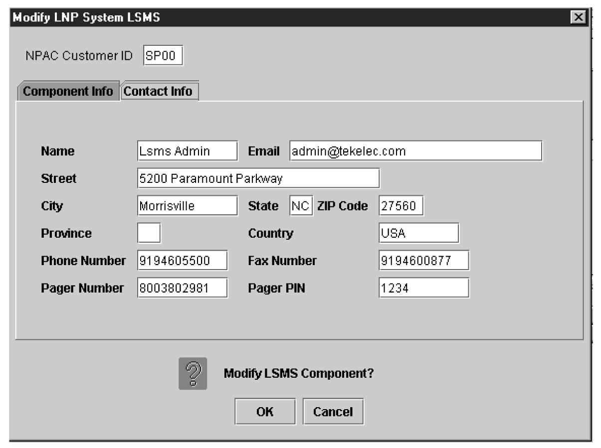
- When finished, click OK to apply the changes.
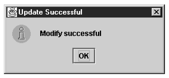
- If the following message appears, click OK in the message window and the GUI will return to the main console window.
Figure 3-12 Modify Successful
- If a message similar to the following appears, a mandatory field is empty or a field is not properly configured.
Figure 3-13 More Fields Needed
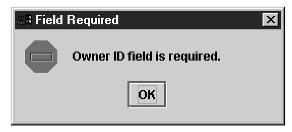
Click OK in the message window and correct the appropriate field. Repeat this step until the message in Figure 3-12 displays.
- If the following message appears, click OK in the message window and the GUI will return to the main console window.
Viewing a Configured LSMS Component
To view configured LSMS component information, use the following procedure.
- From the main menu, select .The View LNP System LSMS window displays. The window usually opens with the Component Info tab displayed.
Figure 3-14 LNP System Menu – View LSMS
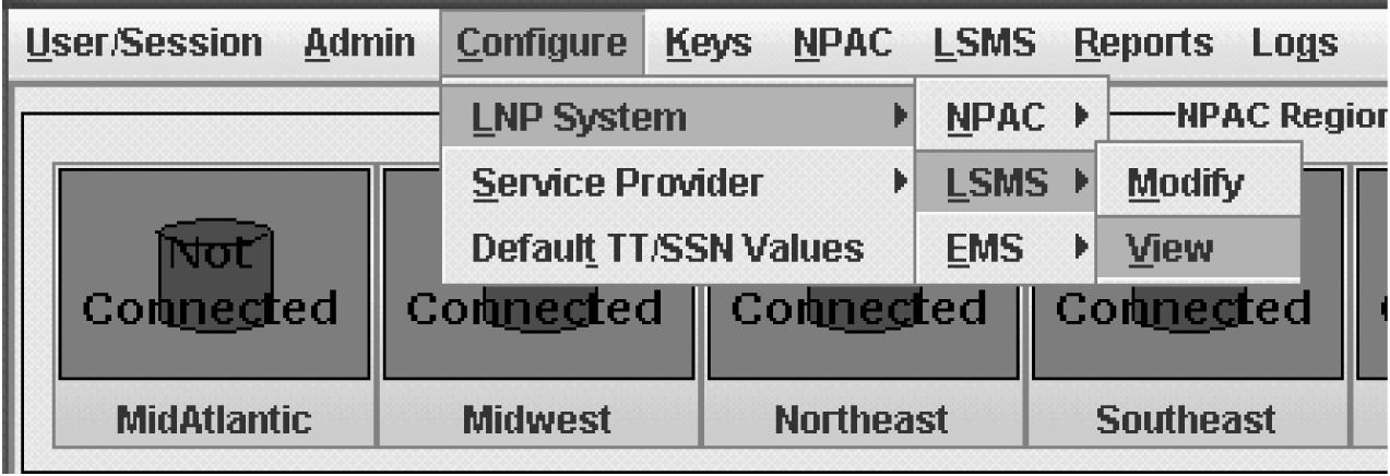
Figure 3-15 View LNP System LSMS Window

EMS Configuration Component
Use the following procedures to manage TekPath or ELAP EMS configuration components:
Creating an EMS Configuration Component
For each network element to be supported by the LSMS, create an EMS configuration component using the following procedure.
Note:
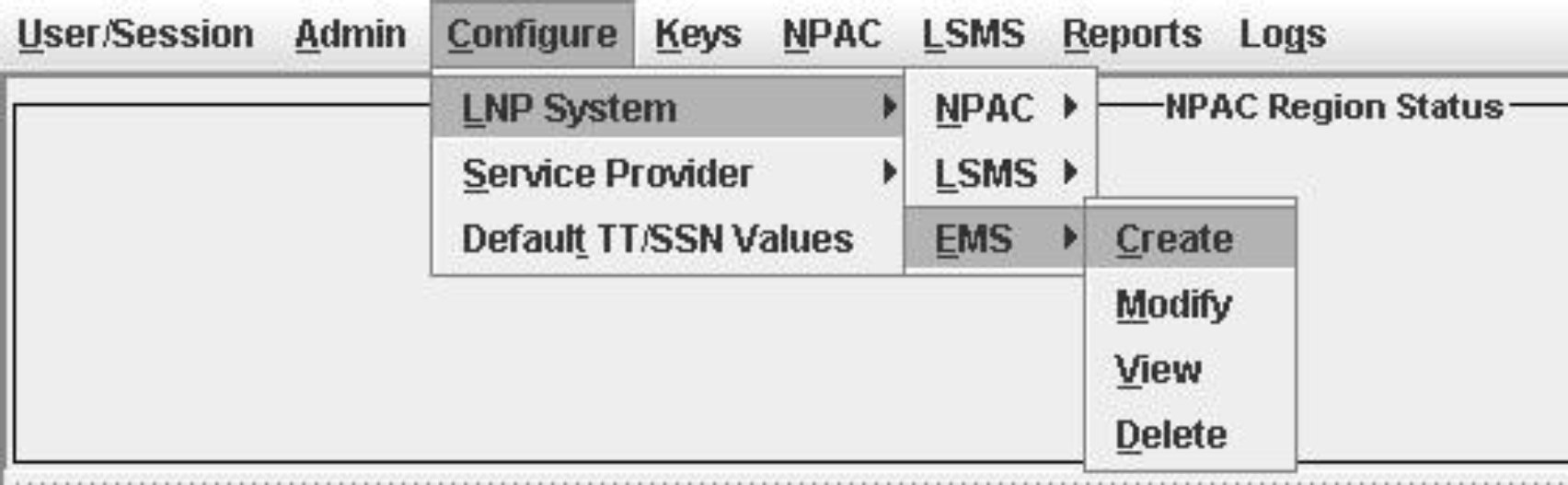
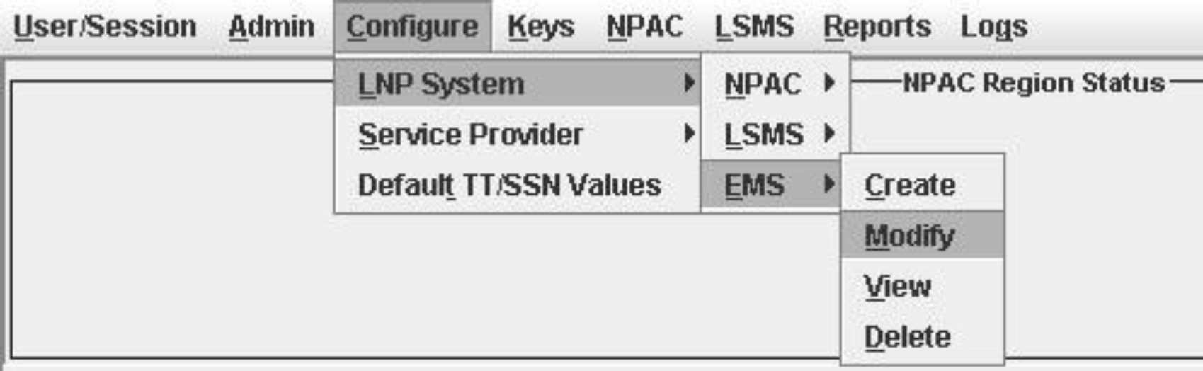
For each EMS configuration created, you must perform a bulk download to the associated EMS/network element. Refer to the LNP Database Synchronization User's Guide for bulk loading procedures.- From the LNP System menu, shown in Figure 3-16, select .
Figure 3-16 LNP System Menu – Create EMS
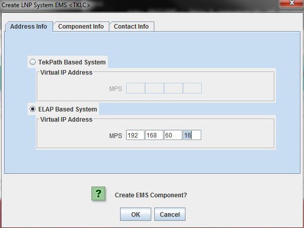
The EMS Configuration Component window, Figure 3-17 displays. The window usually opens with the Address Info tab displayed; if the Address Info tab is not displayed, click its tab to display it.
Figure 3-17 Create LNP System EMS Address Info Tab
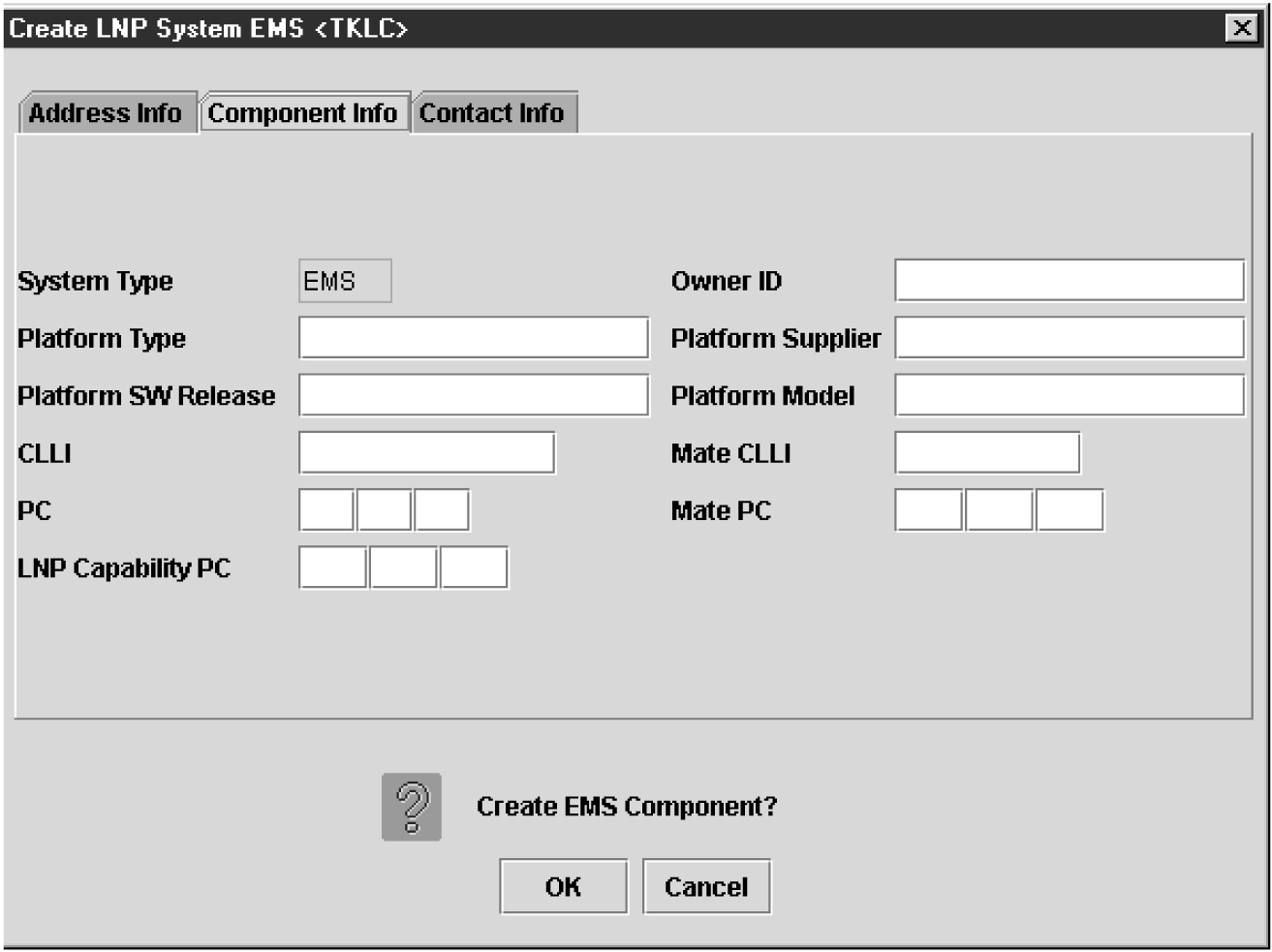
- Click the Component Info tab, shown in Figure 3-19.
Figure 3-18 Create LNP System EMS Component Info
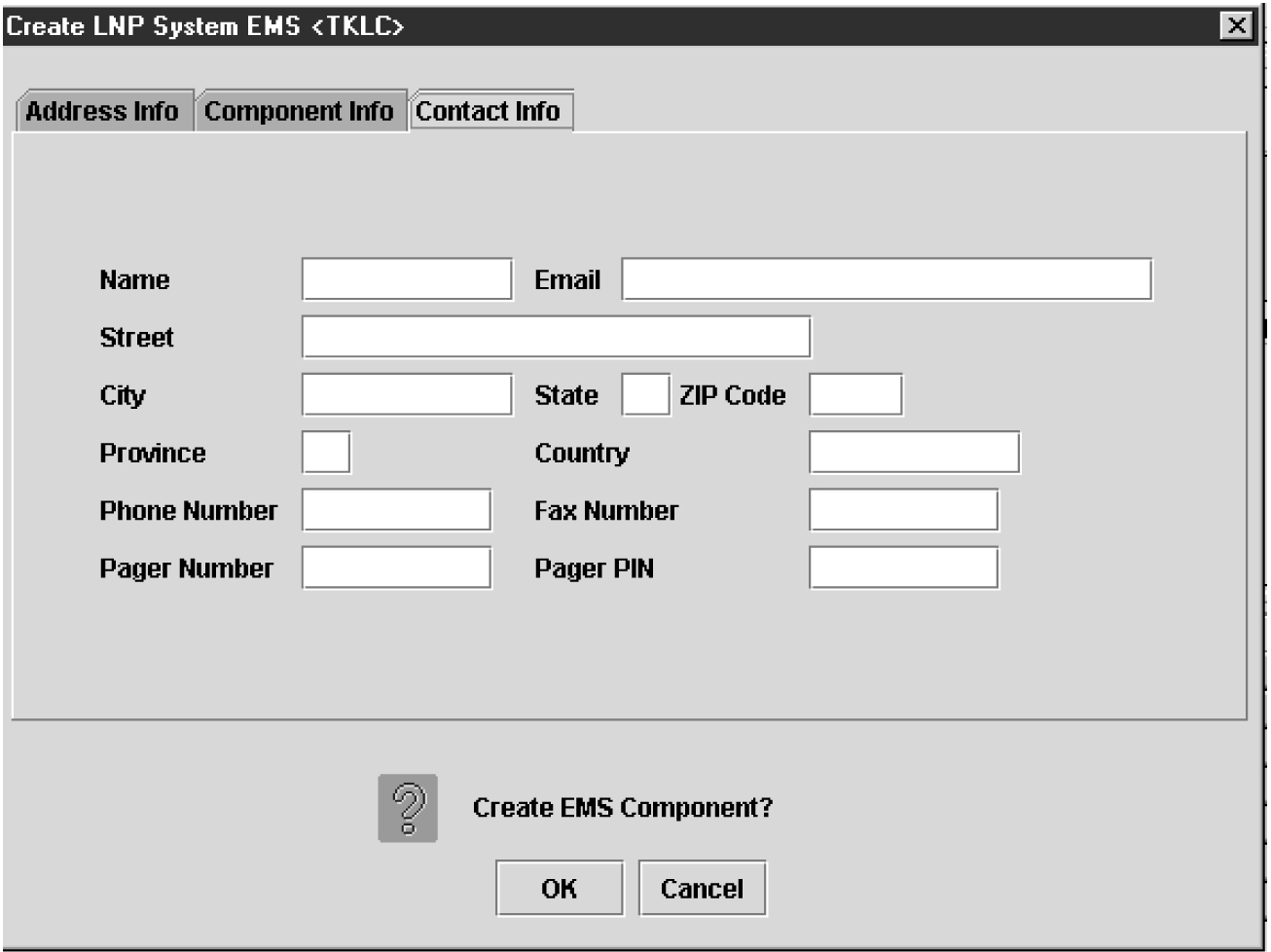
- Click the Contact Info tab, shown in Figure 3-18.
Figure 3-19 Create LNP System EMS Contact Info
- When finished, click OK to apply the changes.
-
If the Update Successful dialog, Figure 3-20 appears, click OK. The GUI returns to the main console window.
Figure 3-20 Update Successful Dialog
-
When a mandatory field is empty or a field is not properly configured, the Field Required Figure 3-21 dialog displays.
Figure 3-21 Field Required Dialog
Click OK and correct the appropriate field.
Repeat this step until you receive an Update Successful notification.
-
Modifying an EMS Configuration Component
To modify an existing EMS configuration component, use the following procedure.
Note:
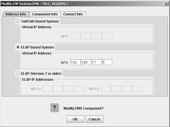
For each EMS configuration created, you must perform a bulk download to the associated EMS/network element. Refer to the LNP Database Synchronization User's Guide for bulk loading procedures.- From the Main Menu, select , as shown in Figure 3-22.The Modify LNP System EMS window, Figure 3-23, appears.
Figure 3-22 LNP System Menu – Modify EMS
 The window usually opens with the Address Info tab displayed; if the Address Info tab is not displayed, click its tab to display it.
Figure 3-23 Modify LNP System EMS Window
- Click OK.The EMS Routing dialog appears, Figure 3-24 .Click OK.
Figure 3-24 EMS Routing Dialog
The Update Successful dialog displays, Figure 3-25.
Figure 3-25 Update Successful Dialog
Figure 3-26 More Fields Needed Dialog

Click OK and correct the appropriate field.
Repeat this step until you receive an Update Successful notification.
Note:
Changes do not take effect until theeagleagent is restarted (refer to "Manually Verifying and Restarting the Eagle Agents" in the Alarms and Maintenance Guide).
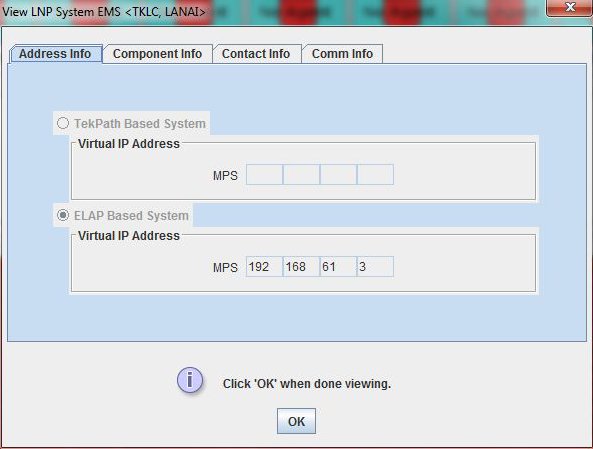
Viewing an EMS Configuration Component
To view EMS configuration component information, use the following procedure.
- From the Main Menu, select .
Deleting an EMS Configuration Component
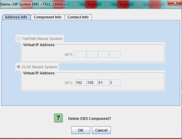
To delete an EMS configuration component, use the following procedure.
- From the Main Menu, select .
- Click OK or Cancel.
- If you click Cancel, you are returned to the LSMS console window.
- If you click OK, the Update Successful dialog displays, Figure 3-29.
Figure 3-29 Update Successful Dialog
Using Key Lists
LSMS maintains a list of keys for each NPAC Service Management System. You use a key list to secure encrypted communications between the LSMS and its associated NPACs.
Key lists are loaded whenever one of the following occurs:
-
LSMS is initially configured
-
The system administrator issues the appropriate key list commands
The LSMS system administrator can view any key list in his system. Key lists can be exchanged off-line to ensure security. Each key list has an assigned expiration date.
During an LSMS GUI session configuration, you load these lists as directed by the LSMS system administrator. You must fully configure one GUI session (including loading key lists) for each NPAC associated with the LSMS.
Use the following procedures to generate a key list, load an NPAC key list, and load an LSMS key list.
Generating a Key List
Each NPAC and LSMS generates a key list for use by the other side. That is, each NPAC generates a key list to be transferred to LSMS for decrypting the message signature sent from NPAC. The LSMS generates key lists that are transferred to the NPAC for decrypting LSMS message signatures sent from LSMS.
The keys in a key list are actually the public key component of a private/public key pair. The originating side keeps the private key component for encrypting the signature when transferred to the receiving side.
A key list contains exactly 1000 keys. Before an originating side can communicate with a receiving side, the receiving side must acknowledge the keys within a key list. For example, if LSMS sends a set of keys to the NPAC, the NPAC creates a file with a checksum for each of the 1000 keys in the list. This newly created file can then be used to acknowledge the keys in the list that were sent to the NPAC.
The following procedure explains how to generate a key list for the NPAC. An overview of the key list creation process is shown below.
Figure 3-30 Flowchart for Generating a Key List

Loading an NPAC Key List
To load an NPAC public key list into the LSMS database, use either of the procedures described in the following sections:
Using the keyutil Command to Load an NPAC Key List
To use the keyutil command to load an NPAC public key list into the LSMS database, use this procedure. Use this command once for the active server; the standby server will be updated with the replicated list automatically.
Using the GUI to Load an NPAC Key List
To use the GUI to load an NPAC public key list into the LSMS database, use this procedure.
- From the main menu, select .The Load NPAC Keys window displays.
Figure 3-31 Keys System Menu – Load NPAC

Figure 3-32 Load NPAC Keys Window
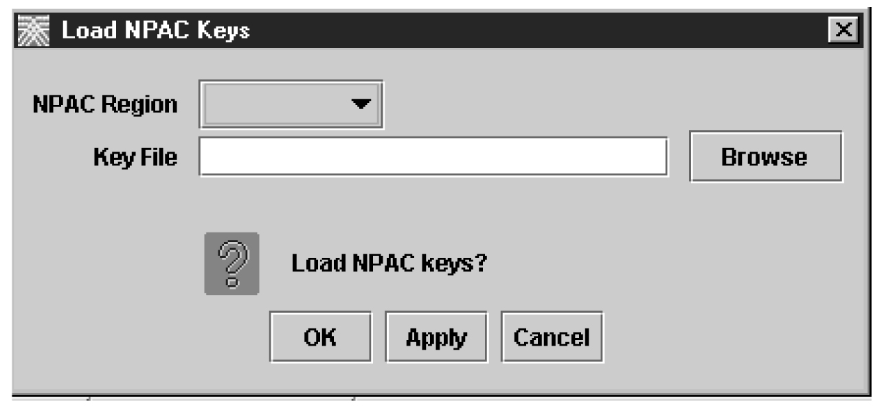
- Click the down arrow shown in the NPAC Region field to display the regions. Then click the region for which you want to load keys.
Figure 3-33 Load NPAC Keys, Select Region Window

Loading an LSMS Key List
To load an LSMS public key list into the LSMS database, use either of the procedures described in the following sections:
Using the keyutil Command to Load an LSMS Key List
To use the keyutil command to load an NPAC public key list into the LSMS database, use the following procedure.
Using the GUI to Load an LSMS Key List
To use the GUI to load an LSMS private key list into the LSMS database, use the following procedure.
- From the main menu, select .The Load LSMS Keys window displays.
Figure 3-34 Load LSMS Keys Window
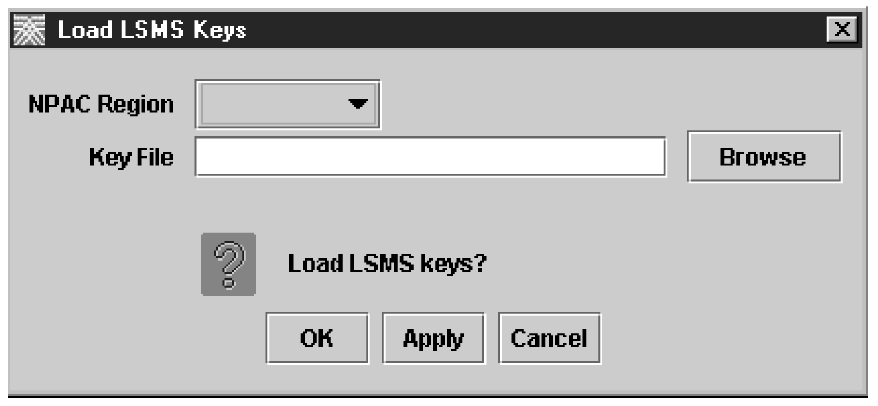
- Click the down arrow shown in the NPAC Region field to display the regions. Then click the region for which you want to load keys.
Figure 3-35 Load LSMS Keys, Select Region Window

NPAC Component Configuration
Use the following procedures to manage NPAC component configuration:
Configuring iconectiv NPAC
The iconectiv NPAC compatibility feature makes the LSMS compatible with the iconectiv NPAC. Configurable options allow the user to specify if a region is connected to Neustar or iconectiv NPAC. The default value of the new configuration option is "N" to signify Neustar NPAC. The end user is able to set the value of the new configuration option per region to Y (for iconectiv).
The format is as follows: <Region Name>_ICONECTIV (for example, MIDWEST_ICONECTIV). To enable a region to connect to iconectiv NPAC, complete the following steps:
There is an audit script to identify the number of NPACs that are connected to iconectiv and Neustar. See Database Administrator's Guide for the NPAC Audit Report.
Modifying an NPAC Component
Use the following procedure to create or modify component configuration for an NPAC. Create components for both the primary NPAC SMS and the secondary NPAC SMS of the regional NPAC.
- If you are creating an NPAC for the first time, perform this step and step 3. (Otherwise, skip to step 4.) Right-click anywhere in the NPAC status area; the pop-menu shown in Figure 3-36 displays.
Figure 3-36 Displaying Inactive Regions
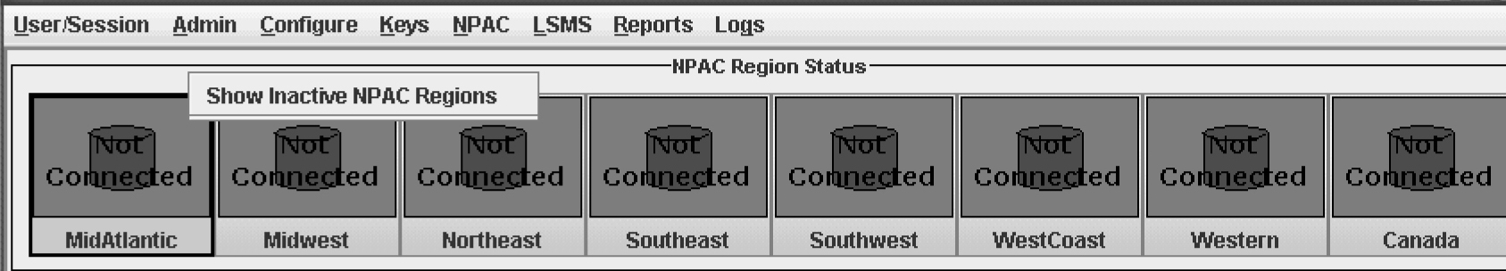
- Click a region for which you have purchased support. The main console window displays.
Figure 3-37 NPAC Status Icons Displayed
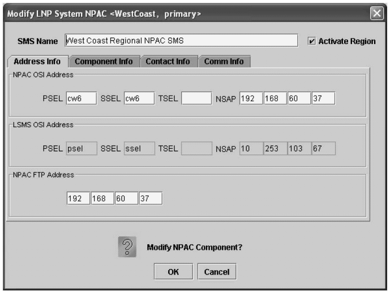
- From the main menu, select or .The Modify LNP System NPAC window displays. In this example, the Primary was selected. The window usually opens with the Address Info tab displayed; if the Address Info tab is not displayed, click its tab to display it.
Figure 3-38 LNP System Menu – Modify NPAC
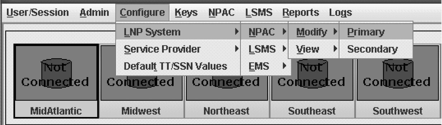
Figure 3-39 Modify LNP System NPAC Address Info Tab
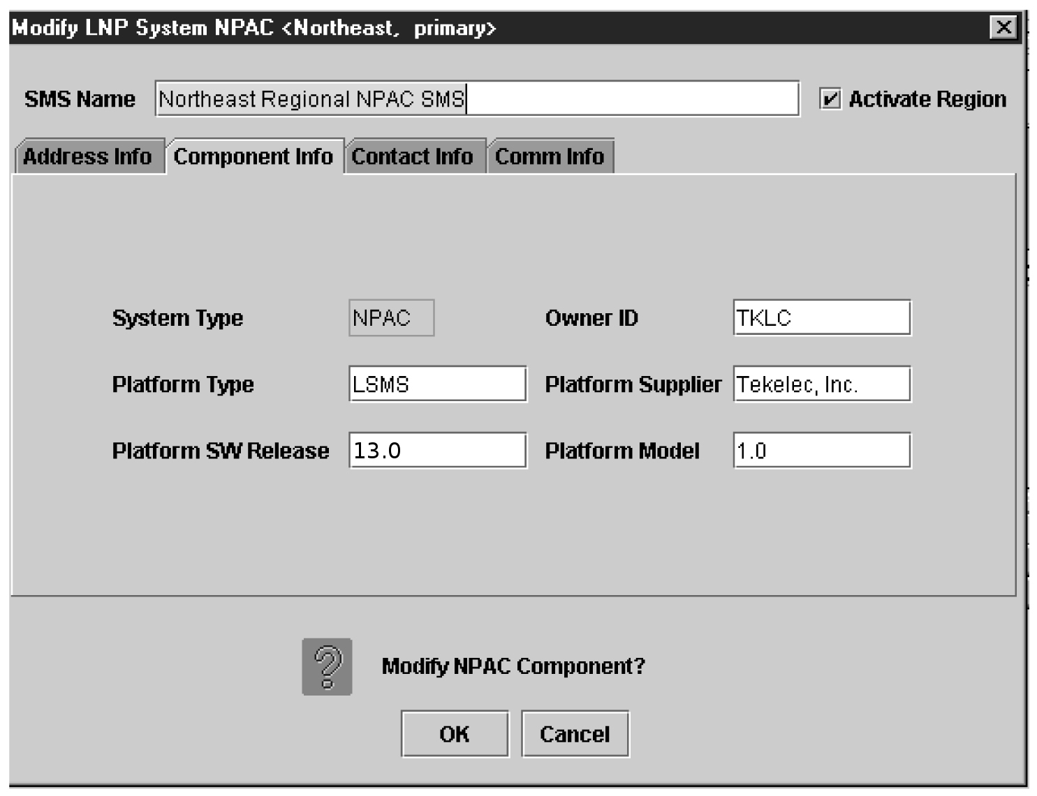
- Click the Component Info tab.
Figure 3-40 Modify LNP System NPAC Component Info
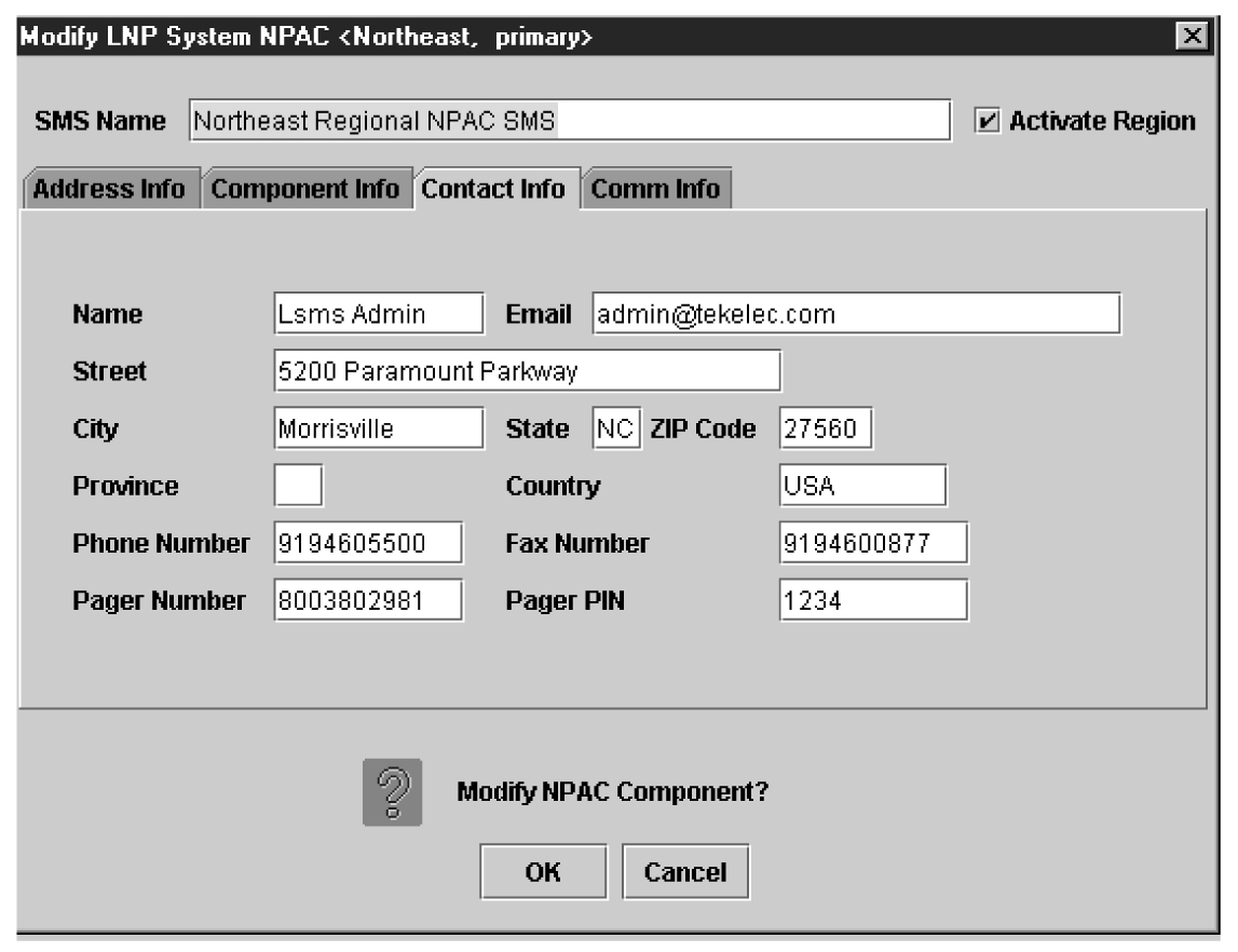
- Click the Contact Info tab.
Figure 3-41 Modify LNP System NPAC Contact Info
- The Comm Info tab is for display purposes only to provide the following information. You cannot modify these fields.
Figure 3-42 Modify LNP System NPAC Communication Info
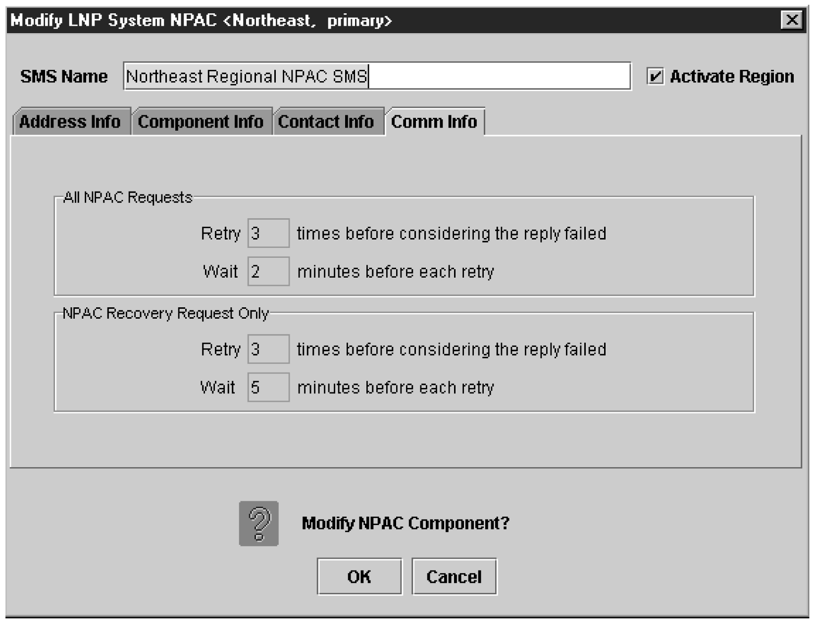
- All NPAC Requests
- Retry—How many times the LSMS will retry a request that the NPAC fails to respond to
- Retry—How long the LSMS will wait for the NPAC respond to a request
- NPAC Recovery Request Only
- Retry—How many times the LSMS will retry a recovery request that the NPAC fails to respond to
- Retry—How long the LSMS will wait for the NPAC respond to a recovery request
- All NPAC Requests
- When finished, click OK to apply the changes.
- If the following message appears, click OK in the message window and the GUI will return to the main console window.
Figure 3-43 Modify Successful
- If a message similar to the following appears, a mandatory field is empty or a field is not properly configured.
Figure 3-44 More Fields Needed
Click OK in the message window and correct the appropriate field. Repeat this step until the message in Figure 3-43 displays.
Note:
If you changed values on the Address Info tab, you must abort and reassociate the NPAC association in order for the modifications to take effect.
- If the following message appears, click OK in the message window and the GUI will return to the main console window.
Viewing a Configured NPAC Component
To view configured NPAC component information, use the following procedure.
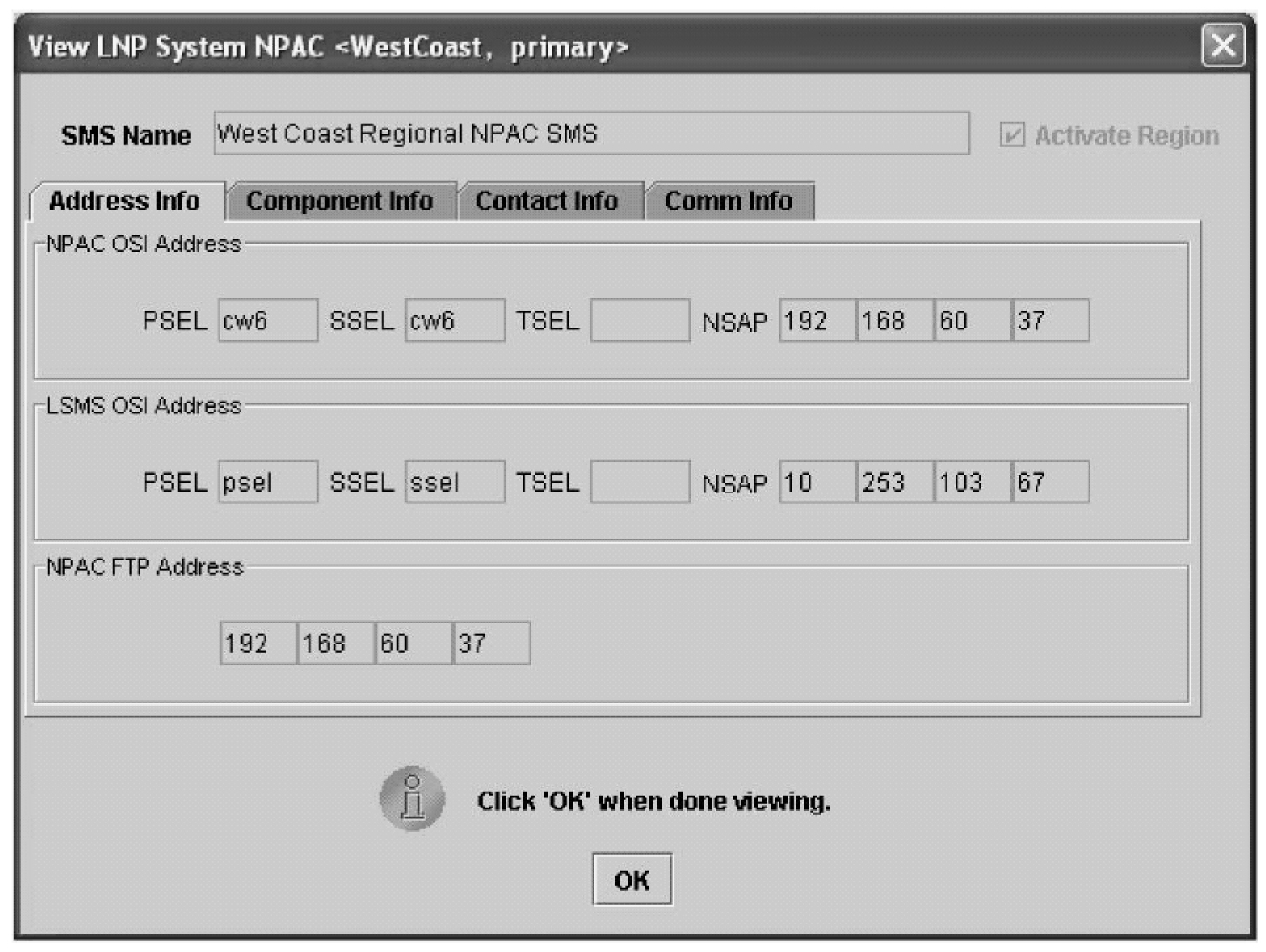
- From the main menu, select or .The View LNP System NPAC window displays. In this example, the Primary was selected. The window usually opens with the Address Info tab displayed.
Figure 3-45 LNP System Menu – View NPAC
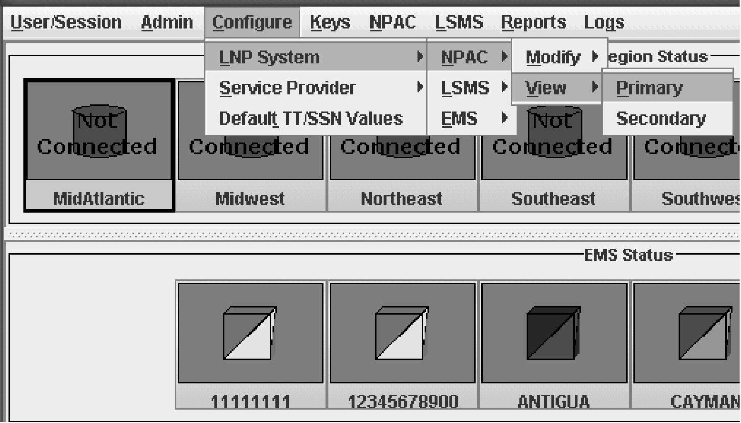
Figure 3-46 View LNP System NPAC Window
Removing a Region
Note:
All the examples are shown for the Southeast region. Southeast can be replaced with <Region name>, which you want to remove.Perform the following steps to remove a region from the LSMS system:
- Deactivate the region from the LSMS GUI:Modify the NPAC configuration:
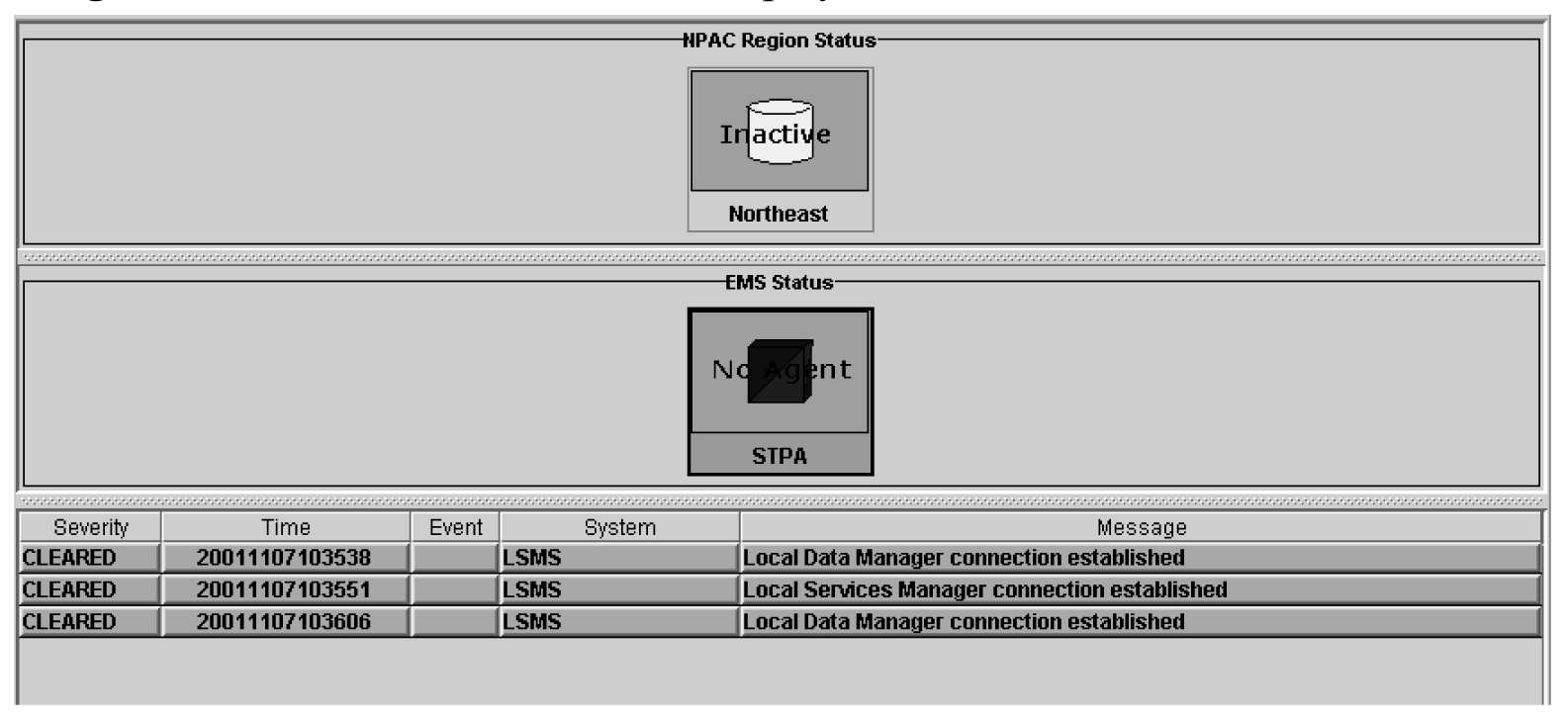
Figure 3-47 LSMS Console

Uncheck Activate region and press OK
Figure 3-48 Modify LNP System NPAC

The NPAC region status will get changed to Inactive.
Figure 3-49 NPAC Region Status

Modifying Default TT/SSN Values
If desired, use the following procedure to modify the default Translation Type (TT) and SS7 Subsystem Number (SSN) values for a given GTT group. Using default settings can simplify the amount of data entry required when creating Default GTTs and Override GTTs (for information about managing Default GTTs and Override GTTs, refer to the Database Administrator's Guide).
- From the main menu, select .The Default TT/SSN Values window displays.
Figure 3-50 Modify Default TT/SSN Values

Figure 3-51 Default TT/SSN Values Window
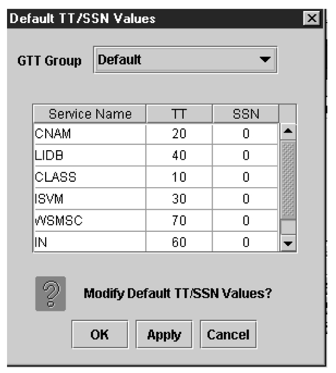
- To change any TT or SSN value, click in the desired table cell; the cell is highlighted while the rest of the row displays in a darker shade, as shown in the example in Figure 3-52.The TT and SSN values must be as follow:
Figure 3-52 Changing Default TT/SSN Values

- TT —Range 1–255
- SSN —Range 0–255, excluding 1 (0 indicates no SSN translation)
- When you are finished, click Apply to apply the changes and stay in this window, or click OK to apply the changes and return to the LSMS Console window.
- If the following message appears, click OK in the message window and the GUI will return either to the Default TT/SSN Values window or to the main console window.
Figure 3-53 Modify Successful

- If a message similar to the following appears, a mandatory field is empty or a field is not properly configured.
Figure 3-54 More Fields Needed

Click OK in the message window and correct the appropriate field. Repeat this step until the message in Figure 3-53 displays.
Working with NPAC Associations
Ordinarily, NPAC associations are managed automatically by the sentry utility, according to the setting of the Activate Region checkbox in the Modify LNP System NPAC window (see Figure 3-39). This section explains how to manually create or abort NPAC associations. You can use the LSMS GUI interface to perform both of these procedures. You can also use the command line utility, lsmsclaa, to create and abort NPAC associations.
The following topics are covered in this discussion of the NPAC associations:
Creating an NPAC Association
Creating an NPAC Association Using GUI
To create an NPAC association with the LSMS using the GUI, perform the following procedure:
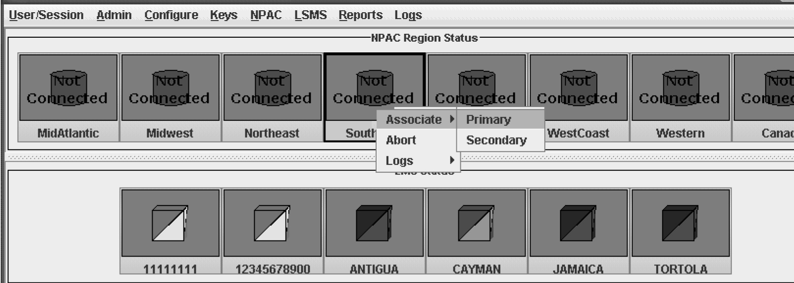
- Click the icon that represents the NPAC that you wish to associate with; then right-click and select Associate.When the LSMS has finished associating with the NPAC, the NPAC status icon displays the text “Associated.”
Figure 3-55 Associate with NPAC
Aborting an NPAC Association
The abort function breaks the association attempt between the LSMS and the NPAC by transmitting the abort command to the NPAC.
- “Aborting an NPAC Association Using GUI”
- “Aborting an NPAC Association Using Command-Line Interface”
lsmsadm or lsmsall user.
Aborting an NPAC Association Using GUI
To abort an NPAC association with the LSMS using the GUI, perform the following procedure:
- Log in to LSMS as a member of the permission group that is authorized to perform this operation.
- Click the icon that represents the NPAC whose association you wish to abort; then right-click and select Abort.
- When the LSMS has finished aborting the association with the NPAC, the NPAC status icon displays the text “Not Connected.”
Postfix
Postfix is an alternative mail program to the Sendmail program.
Note:
The Postfix daemon must be restarted manually after any operation that causes the host to reboot. Postfix is disabled by default.The normal configuration of Postfix requires DNS (Domain Name System). Postfix uses fully qualified hostnames for source and destination resolution.
Note:
The Postfix configuration affects only the local server.The following topics are covered in this discussion of Postfix.
Configuring Postfix
Modifications to the Postfix configuration files or aliases database require the Postfix utility to be restarted. To configure Postfix, perform the following procedure:
Caution:
Loss of data can result if you do not properly configure Postfix. For technical assistance, call the Customer Care Center.Starting and Stopping Postfix
To start Postfix, use this command:
# /usr/sbin/postfix start
To stop Postfix, use this command:
# /usr/sbin/postfix stop
Note:
The user must be root to start and stop Postfix.