4 Working with Projects, Data Schemas, and Data Elements
This chapter provides information about Design Studio projects, data schemas, and data elements. Also, it provides high-level information about modeling data elements.
Working with Projects
Design Studio projects contain artifacts (entities, data, rules, code, and so forth) that you use to model and deploy Design Studio cartridges. Your solution uses various types of projects. For example, you use projects to build cartridges that can be deployed to a server, for version management, for sharing, and for resource organization.
You can create various types of projects and you can extend cartridges that you purchase with your own projects. Oracle Communications supports a library of extensible cartridges that are fully compatible with Design Studio and provide a basis from which to assemble solutions.
The most common types of projects you use in Design Studio are:
-
Model projects, which contain data common to multiple cartridge projects.
-
Cartridge projects, which contain collections of entities and supporting artifacts that represent a cartridge deployed to a run-time environment.
-
Environment projects, which you use to manage attributes associated with your run-time environments.
In each project, you can model the data necessary to achieve your solution (and share that data across all projects in the workspace) build and package the projects, and test them in run-time environments.
Application integration and cross-product modeling and data sharing reduce the effort and time to deploy solutions. Design Studio supports the design-time configuration for integrated (or standalone) service fulfillment solutions and for network resource management solutions.
Importing Projects
One way to start working in Design Studio is by importing domain-specific and vendor cartridges into Design Studio and using these cartridges as the foundation for your new solutions. For example, if you have obtained cartridges from Oracle, you can import them into Design Studio and reuse their components to create your own cartridge projects.
There are multiple methods for importing data into Design Studio. The methods depend on your own preferences and on the applications with which you are working. For example, Oracle Communications ASAP enables you to import data directly from an existing ASAP run-time environment, and Oracle Communications Order and Service Management (OSM) enables you to import existing XML data models. When importing data for Design Studio application plug-ins, it may be necessary to refer to the Help specific to the application for more information.
Note:
Importing from ASAP run-time environments and from OSM XML models is intended for migration purposes only.
When importing Design Studio for Inventory cartridge projects that include changes to tool tips or characteristic display names, you must redeploy the Oracle Communications Unified Inventory Management (UIM) application server when you deploy the cartridge that contains the changes.
When you import a cartridge, it becomes a project in the current workspace. Some cartridges are sealed, meaning that they are read-only. Sealed cartridges cannot be modified without first being unsealed.
Some projects reference entities in other projects, and these references create dependencies among the projects. If you import a cartridge project that has dependencies on other cartridge projects that are not in the current workspace, Design Studio displays an error. Import all dependent cartridges, then clean all projects to remove the errors. See "Working with Project Dependencies" for more information.
Upgrading Projects
When working in a new version of Design Studio, you must upgrade projects from the previous Design Studio version to the latest Design Studio version. Additionally, you must obtain and import the latest versions of all sealed productized versions if you want to use the cartridge in the updated version. During the upgrade process, Design Studio automatically detects old project versions and completes all necessary project upgrades in the workspace.
See Design Studio Installation Guide for more information about upgrading projects.
Controlling Project Visibility in a Workspace
Design Studio solutions can contain large numbers of productized, sealed, and application-specific projects that are not directly related to your work. You control which projects appear in your workspace by creating and applying a filter, called a working set.
The projects that a working set filters out exist in the workspace and remain open but do not appear in the Studio Projects view. Also, you can define a separate working set for the Solution view to control visibility of project entities at the root level.
For example, you can facilitate design modeling and workspace navigation by creating a working set that displays only those projects related to your present design work. The working set can filter projects based on the project type and based on a tag that you associate with a project. Working set filters are limited to the workspace in which they are defined.
One working set is delivered with Design Studio and is applied to the Studio Projects view when you install Design Studio. This working set is named Exclude Base Projects, and it excludes from display all Design Studio base projects, any projects associated with the Base Project tag, and all non-Design Studio projects (such as Eclipse projects and Java projects). The Exclude Base Projects working set is not editable, but you can deactivate this working set filter. See the Design Studio Help for information about deselecting a working set and for more information about controlling which projects appear in your workspace.
Working with Model Projects
Model projects are collections of data elements intended to be referenced by other projects in a workspace to fulfill a solution. Model projects include simple data elements and structured data elements that are not specific to any one Oracle Communications application and that enable you to share that data across a solution.
Entities in Design Studio application projects can reference data in a model project. You can model these data elements once, then configure different applications to reference these data elements, as appropriate. This modeling strategy enables you to identify which entities in a solution share the data elements in the solution.
For example, an Activation project entity, an OSM project entity, and an Inventory project entity can all share the same data elements (for example, the data elements Caller ID, Call Waiting, and Call Forwarding) created and saved in a model project.
Working with Cartridge Projects
Cartridge projects contain collections of entities that you can deploy to a run-time environment to support your business processes (for example, cartridges deployed to Oracle Communications Order and Service Management run-time environments provision services requested on incoming sales orders). When modeling application-specific entities in Design Studio, you configure all entities in a cartridge project.
Cartridge projects can have design-time dependencies on other cartridge and model projects. During project builds, Design Studio adds the necessary design artifacts from any dependent projects to your cartridge project.
Cartridge projects can be built and packaged into deployable cartridges. A cartridge is a collection of entities packaged into an archive file, which you can deploy to a run-time environment.
You can create the following cartridge projects:
-
Activation IPSA project
-
Activation project
-
Activation SRT project
-
Integrity project
-
Inventory project
-
Order and Service Management Composite project
-
Order and Service Management project
See the Design Studio Help for more information about these cartridge projects.
Working with Environment Projects
Environment projects enable you to manage the attributes associated with your run-time environments, including connection attributes, projects ready to be deployed, projects previously deployed, and associated project attributes such as the version and build numbers.
You must create at least one environment project. Environment projects can be shared among all team members who use the same test environment. You work with environment projects and their entities in the Environment perspective.
Working with Project Dependencies
Projects have dependencies on other projects when entities in one project reference entities in another project. These dependencies enable you to share data elements and entities across applications. For example, an OSM project entity might reference the Caller ID, Call Waiting, and Call Forwarding data elements in a model project.
Defining dependencies among projects helps eliminate circular dependencies and duplicate data elements from your data solution, and enables you to better understand how projects are related. Defining project dependencies ensures that all of the data a cartridge project requires is available when you deploy the cartridge project to a run-time environment.
When defining project dependencies, you can specify whether the dependency is required in the Design Studio workspace or whether the dependency is required in the Design Studio workspace and in the target run-time environment.
When you build a project, Design Studio ensures that all entities that are referenced in but defined outside of the project are declared. Design Studio saves the project dependency information and uses this information to validate dependencies at deployment.
Note:
Oracle recommends that you plan relationships between projects and configure project dependencies early in your development cycle.
Project Dependency and Data Modeling
Project dependencies control the data that is available when you model cartridge projects. Design Studio restricts the data that is available (in data selection dialog boxes and in views) to data defined in the project and in dependent projects only. Filtering the data that is available helps prevent circular dependencies and unintended model reuse.
Project Dependency Warnings and Errors
If you configure a cartridge project to reference content in other cartridge projects without declaring project dependencies, Design Studio creates an error or a warning. You control this level of severity, based on how you define the diagnostic level in the Project editor. See the Design Studio Help for more information.
Project Dependency and Cartridge Deployment
The dependencies defined for a project impact the order in which you deploy cartridge projects. You must deploy all dependent cartridges first. For example, if project A depends on project B and project C, and project B depends on project C, when you deploy project A, Design Studio determines that you must deploy projects C and B first (and in that order).
Working with Data Schemas
A data schema is a formal description of a data model, expressed in terms of constraints and data types governing the content of elements and attributes.
You use data schemas when defining products, services, and resources, including the associated actions and the information necessary to perform the processes and tasks for those actions, as well as the interface definitions for integrating between applications.
All data elements are created and saved in data schemas, which can be accessible across all projects in a workspace. Design Studio automatically creates a project-specific data schema when you create a cartridge project (for example, an OSM, Activation, Inventory, or Network Integrity project). You can use this default schema to contain the data you require to model the project, you can create multiple schemas in the same project, or you can create schemas in common projects. You can model your cartridge project using data from any combination of these data schemas.
Model project data schemas include data elements that you want to use across a fulfillment solution. They are product-agnostic; that is, the data elements stored in a model schema are independent of any application project.
<?xml version="1.0" encoding="utf-8"?>
<xs:schema elementFormDefault="qualified"
   targetNamespace="http://www.oracle.com/ServiceActivation/MobileGSMActivation"
   xmlns="http://www.metasolv.com/ServiceActivation/MobileGSMActivation"
   xmlns:mca-serviceentities="http://www.oracle.com/MCA/ServiceEntities"
   xmlns:xs="http://www.w3.org/2001/XMLSchema">
<xs:import namespace="http://www.metasolv.com/MCA/ServiceEntities"/>

<xs:element name="C_ACME-GSM_1.0.0_ADD_GSM_SUBSCRIBER">
   <xs:complexType>
      <xs:sequence>
         <xs:element name="TelephoneNumber_TN" type="TelephoneNumber_TNType"/>
        <xs:element name="TelephoneNumber_TNType"
            type="TelephoneNumber_TNTypeType"/>
        <xs:element name="callDisplay" type="callDisplayType"/>
      </xs:sequence>
   </xs:complexType>
</xs:element>

<xs:simpleType name="callDisplayType">
   <xs:restriction base="xs:string">
      <xs:maxLength value="255"/>
   </xs:restriction>
</xs:simpleType>
<xs:simpleType name="TelephoneNumber_TNType">
   <xs:restriction base="xs:string">
      <xs:maxLength value="255"/>
   </xs:restriction>
</xs:simpleType>
<xs:simpleType name="TelephoneNumber_TNTypeType">
   <xs:restriction base="xs:string">
      <xs:maxLength value="255"/>
   </xs:restriction>
</xs:simpleType>
</xs:schema>
Working with Data Elements
There are two types of data elements, simple data elements and structured data elements. Simple data elements are reusable data types that contain no child dependencies. A simple data element has no structure, and is associated (directly or indirectly) to a primitive data type (Integer, Boolean, String, and so forth). See "About Primitive Data Types" for more information.
Structured data elements are reusable data types that include embedded data types and are containers of simple data elements and other structured data elements. For example, you might create a structured data element called building that contains the floor, room, aisle, rack, and shelf child data elements.
About Primitive Data Types
Design Studio supports primitive types defined by the XML Schema specification.
Table 4-1 lists the full set of supported types and their formats. These types represent the foundation from which all data elements in Design Studio are derived.
Table 4-1 Primitive Data Types Supported in Design Studio
| Type | Format |
|---|---|
|
Structure |
Hierarchical construct of structures and simple data elements. |
|
Boolean |
true or false |
|
Date |
yyyy-mm-dd For example: 1971-05-21 |
|
Date Time |
yyyy-mm-ddThh:mm:ss.szzzzzz where zzzzzz represents a time zone, .s represents fractional seconds Fractional seconds and time zone are optional. Use Z for Coordinated Universal Time (UTC), or UTC relative form (+ | -) hh':'mm For example: 1971-05-21T14:22:35.2Z, 1971-05-21T14:22:35+05:00 |
|
Time |
hh:mm:ss For example: 14:22:35 |
|
Integer |
Infinite set {..., -2, -1, 0, 1, 2, ...} using decimal digits |
|
Long |
Between -9223372036854775808 and 9223372036854775807, inclusive |
|
Float Double Heximal |
Lexical representation consisting of a significand and an optional exponent. For example: -1E4 1267.43233E12 12.78e-2 12 |
|
Hex Binary |
[0-9a-fA-F] tuples Must have an even number of hexadecimal digits. Hex binary allows length restriction. For example: A1, 80FF, 18A2C797 |
|
String |
Series of UTF-8 characters. String allows length restriction (default 0 to 40). |
About Data Element Icons
Design Studio communicates properties of data elements with associated icons. These icons include problem marker severity, data element multiplicity, and some state details. Data elements that are read-only appear in gray.
Note:
The information conveyed through these icons is also available on the Details tab. The problem marker information is available in the Problems view. See Design Studio Help for more information about the Details tab fields and Problems view.
Figure 4-1 displays a list of icons and the manner in which they appear with data elements.
Figure 4-1 Design Studio Data Element Icons
Description of "Figure 4-1 Design Studio Data Element Icons"
Modeling Data Elements
This section describes the features and functionality you use in Design Studio to model solutions for and share data across service fulfillment and network and resource management business solutions.
About the Data Modeling Tabs
Some Design Studio editors include tabs in which you can model information about data elements. These tabs appear in multiple Oracle Communications applications and enable you to configure entities by modeling a data tree to hierarchically represent all associated data elements. These tabs facilitate reusing data elements within a modeling solution and provide tools for locating and using existing data elements.
The tabs consist of a data tree and subtabs. You select a data element in the data tree to review and model details of the selected data element. You open a context menu from the data tree to perform various types of refactoring operations on the data elements.
About the Details and Attributes Tabs
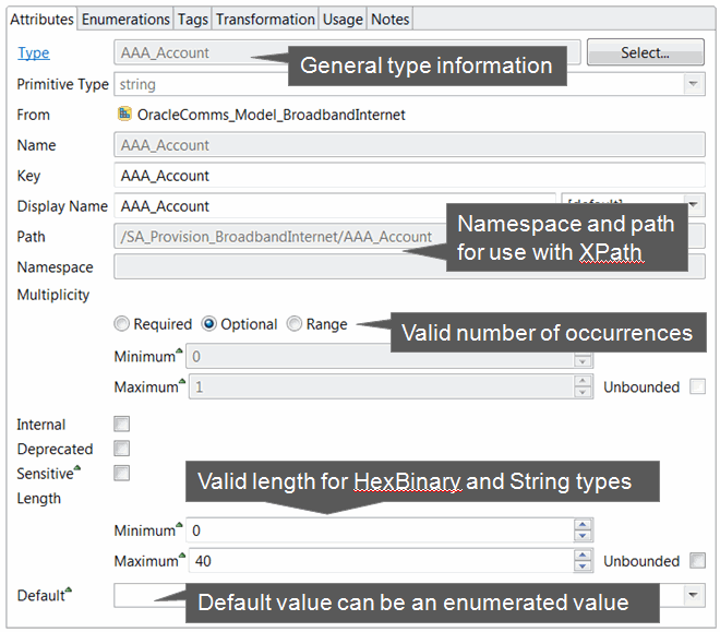
You use the Details tab and the Attributes tab to define attributes of a data element (such as the name and primitive type), as well as specific constraint values for a data element.
About the Enumerations Tab
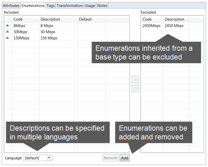
You use the Enumerations tab to define sets of valid values for data elements.
Enumerations define values for data elements that are available for selection in a run-time environment. For example, you can define a set of values that appear as lists in the run-time environment.
About the Tags Tab
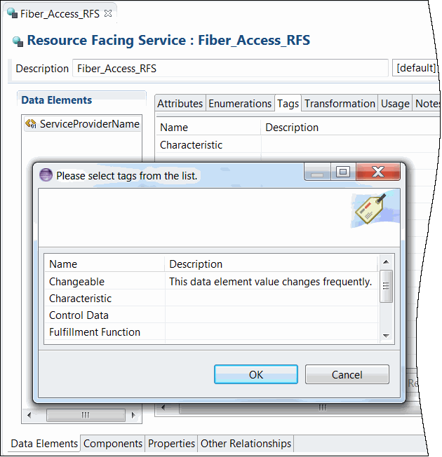
You use the Tags tab to characterize data elements by associating the data elements with predefined keywords called tags. Tags help you filter and search for data elements that are associated with specific Oracle Communications applications.
The tags delivered with Design Studio cannot be inherited.
About the Usage Tab
You use the Usage tab to review the projects and entities in which a data element is used and to review all references to a specified data element.
About the Notes Tab
Use the Notes tab to annotate data elements with descriptions or other applicable information to support the data element.
Design Studio supports multiple languages for this tab. The field at the top of this tab displays your list of languages. If your preferences are set up to work in one language only, the system displays only [default].
Data Element Application Details
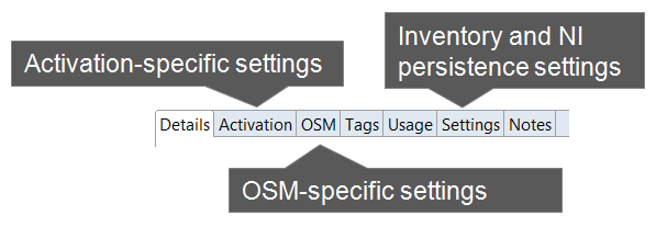
You can define for data elements application-specific properties, which you configure using the application-specific data element tabs. For example, you can define information for data elements that are tagged as Inventory characteristics, or you can define behaviors for data elements that will appear in an OSM run-time environment.
About Data Modeling Strategies and Techniques
Design Studio enables you to:
-
Create new data elements that obtain attributes from other data elements. See "Leveraging Information from Existing Data Elements" for more information.
-
Use components and features to search for and organize data elements. See "Organizing and Searching for Data Elements" for more information.
-
Use the refactoring tools to normalize data models. See "Refactoring Data Models" for more information.
Leveraging Information from Existing Data Elements
To increase modeling efficiency, Design Studio enables you to create new data elements that obtain attributes from other data elements. In Design Studio, you can leverage information using two methods:
-
Deriving from a base type element (where the new element automatically obtains the information in the base element
-
Extending entities
Deriving from Base Type Elements
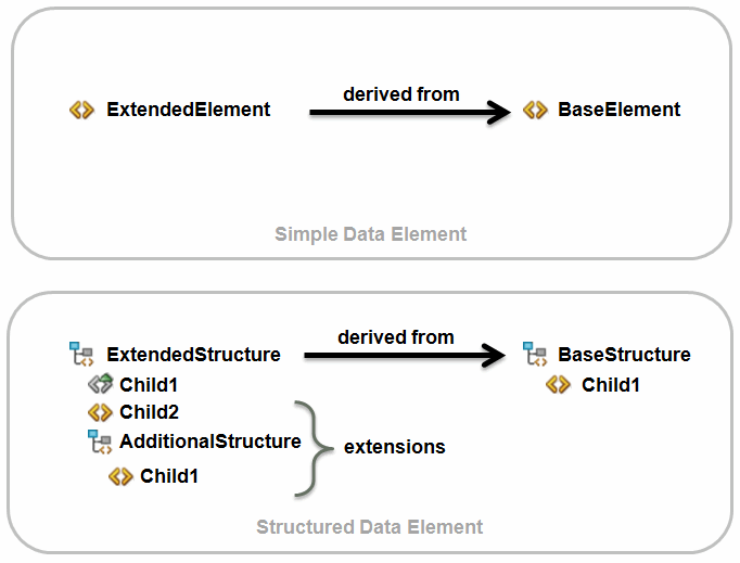
Leveraging information already defined for base types enables you to define attributes once, share the common attributes among multiple entities, and edit those entities in a single location. Changes that you make to a base type are automatically saved to all entities that derive from that base type.
For example, if a structured data element person contains the first_name, last_name, and social_security_number child elements, you can leverage the information defined for person by using it as a base type for a new structured data element called employee. You can add to employee the employee_number, hire_date, and department child elements. If you make changes to person, Design Studio automatically updates employee with the same changes.
You can override some of the information derived from the base type element. When you override these fields, Design Studio does not automatically update that value when the base type value is changed. Rather, Design Studio retains the override value that you defined for the subtype field.
Attributes that you can override include the minimum and maximum number of times the element can appear as a field in a run-time environment, the default value defined for the element, the length defined for string and HexBinary data elements, internal documentation for the element, and so forth.
Aliased Data Elements
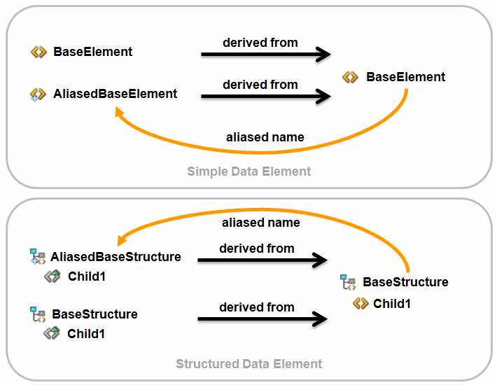
Typically, derived data elements inherit the name of their base type. If you want to give a derived data element a unique name, you can define an alias for the data element. You can use an alias to give context to the specific use of a data element or to distinguish multiple data elements derived from the same base type.
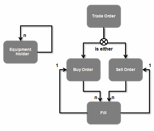
Data Element Recursion
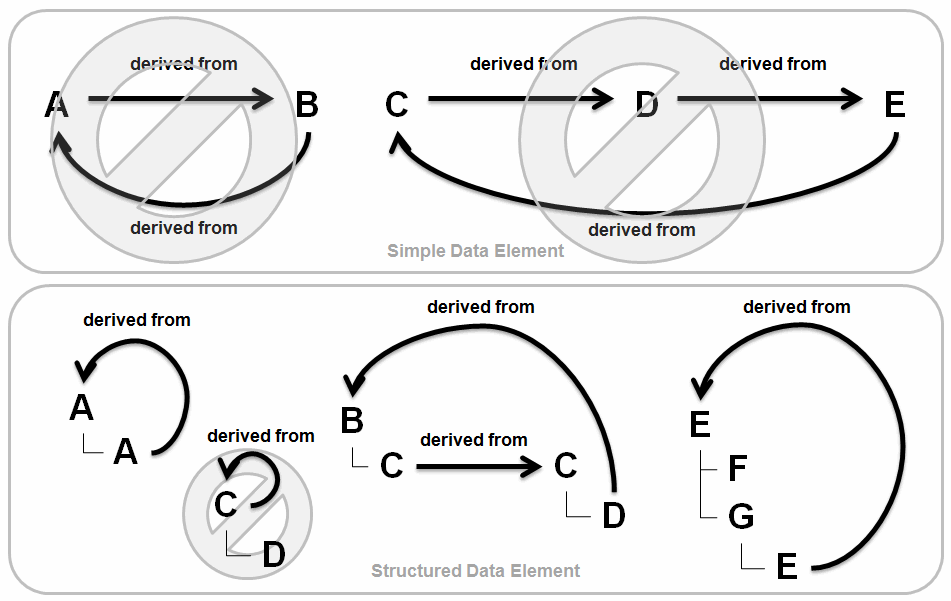
Data element recursion refers to a pattern where a data element repeats in the ancestry of derived data elements. Recursion provides useful patterns for data modeling, and Figure 4-8 demonstrates some of these patterns. When recursion is present, the point of recursion starts an infinite nesting of inherited data elements. Most variants of structured data element recursion are valid in Design Studio.
Simple data element recursion, however, is not valid in Design Studio models because a data element can never resolve to a primitive type. Design Studio validates base type selection to prevent you from defining simple data elements as recursive. If an invalid recursion occurs, Design Studio generates an error marker during the build process.
Structured data elements with recursion inherit the data elements of the base type. The Design Studio user interface expands to display a finite number of recursion levels (the number of levels is configurable in the workspace preferences). All structured data elements, including derived structured data elements, can be extended to include additional child data elements.
A recursive reference can be indirect when two structures have data elements that derive from each other. Indirect relationships can be realized through multiple levels of derivation and are not immediately apparent. Figure 4-9 illustrates two different data models using recursion.
Figure 4-9 Data Models Illustrating Recursion
Description of "Figure 4-9 Data Models Illustrating Recursion"
Entity Extensions
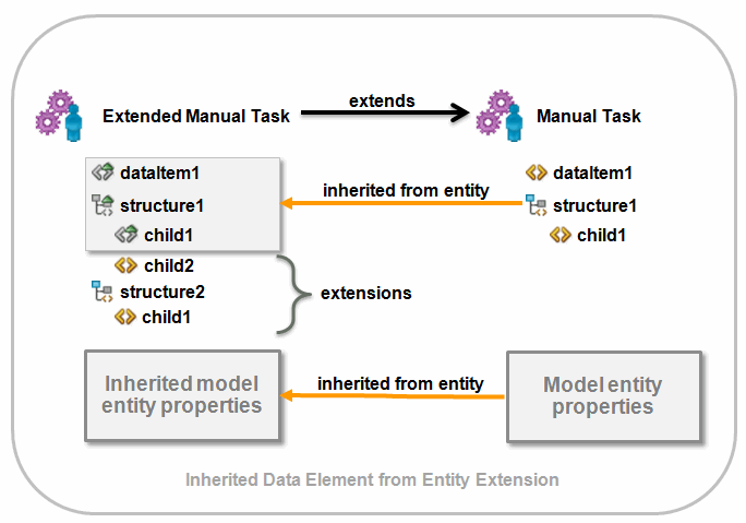
You can increase your modeling efficiency by extending entities. Data extensibility enables you to leverage data when building new, similar entities. For example, you can extend orders and tasks. When you extend one entity from another, the target entity inherits all of the data elements defined for the extended entity.
If you extend an entity that includes structured data elements, you can add any number of additional simple and structured child elements (the inherited data elements are read-only).
Inheritance
When you extend one entity from another, the target entity inherits all of the data elements defined for the extended entity. These inherited data elements are read-only. Unlike data elements inherited from a base type, the inherited data elements can be extended at any level of the inherited data element.
For example, an OSM manual task can extend another manual task. The data elements modeled on one manual task are extended to another manual task. The target entity can include data elements in addition to those data elements the target entity inherits from the extended entity.
Organizing and Searching for Data Elements
Design Studio helps you keep your data models organized and locate specific data elements during model configuration.
Data Model Hierarchies
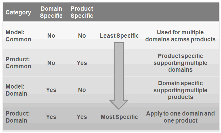
Figure 4-11 defines the categories of projects in which you can model data schema entities. Understanding to which category a project belongs will help keep your model organized and efficient. When determining the location for data elements, consider how specific that data element is to a product or to a domain.
For example, common product projects are often sealed models provided by the product teams for solution development, whereas domain-specific model projects are ideal for domain-specific content.
Oracle recommends that you always model in the most generic category possible.
Dictionary View
You can use the Dictionary view to facilitate data modeling. The Dictionary view presents a view of the Data Dictionary, including all reusable data elements contributed by entities in the workspace.
The Dictionary view includes an option to filter data elements visible only to the active editor, which enables you to hide those elements in the Data Dictionary that are not intended to be used by specific entities. Additionally, you can filter this view to display only those entities flagged with a specific tag or defined by a specific entity type.
Search fields provide an additional mechanism to locate data elements.
Navigation and Modeling Tips
Design Studio includes shortcuts for navigation. When switching between views and editors, these shortcuts help minimize modeling time and effort.
For example, you can double-click any editor or view tab to maximize the editor or view area. Double-click the tab again to return it to the original size. From the Dictionary view, double-clicking a data element opens the related entity. Double-clicking a data element in an editor opens the base type data element. Clicking the Type field link in the Data Schema editor Details tab opens the base type of an element.
Also, you can drag data elements from the Dictionary view to an editor data tree when modeling your solution.
Refactoring Data Models
In Design Studio, refactoring is the process of changing data elements without modifying the external functional behavior of a solution.
Refactoring in Design Studio enables you to propagate data model changes across the entire solution without sacrificing model integrity. You can rename, change the location of, copy, and move data elements. Additionally, refactoring enables you to copy data elements to create similar data entities, and to create modular and reusable data structures. See the Design Studio Help for more information.
The following sections include additional information about some of the refactoring actions, all of which are available from the Refactoring option in content menus.
Renaming Entities and Data Elements
The rename refactoring option ensures that all references are properly updated when you rename an entity or a data element, and that all aliased names are maintained.
Design Studio displays a detailed list of all the changes to be performed against the workspace that you can review.
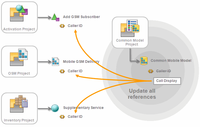
In Figure 4-12, a data element named Caller ID is renamed to Call Display. The Rename refactoring functionality ensures that the entities that reference the data element (in this example, an atomic action called Add GSM Subscriber, an OSM order called Mobile GSM Delivery, and an Inventory supplementary service called Supplementary Service) are updated with the new data element name, Call Display.
Figure 4-12 Refactoring Solutions Using Renaming
Description of "Figure 4-12 Refactoring Solutions Using Renaming"
Removing Entities and Data Elements
When you remove entities or data elements from the workspace, Design Studio locates and removes all referenced instances. When you remove entities or data elements, ensure that other constructs in the solution are updated appropriately.
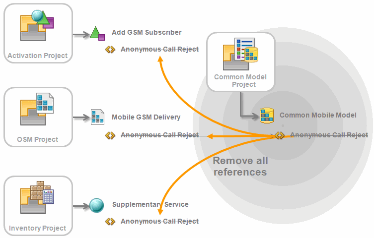
In Figure 4-13, a data element named Anonymous Call Reject is deleted. The Design Studio refactoring functionality ensures that the data element is also deleted from all entities that reference the data element (in this example, an atomic action, an OSM order, and an Inventory supplementary service).
Figure 4-13 Refactoring Solutions Using Remove
Description of "Figure 4-13 Refactoring Solutions Using Remove"
Making Data Elements Reusable
When a structure nested inside a structure is identified as a data element suitable for reuse, you can convert that structure into a reusable root level structure.
Often, the action to make an element reusable is combined with an action to move the data element to a generic location, such as a common data schema entity. In Figure 4-14, the Subscriber structure will be converted into a reusable data element. The original structure is a new, derived structure of the same hierarchy.
Figure 4-14 Refactoring using Make Reusable
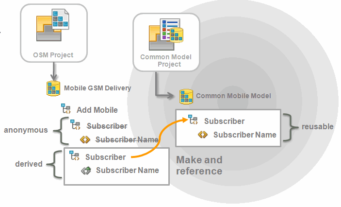
Description of "Figure 4-14 Refactoring using Make Reusable"
Replacing Data Elements
Figure 4-15 demonstrates how a data element can be replaced with another compatible data element to normalize the solution data model, or to migrate to a newer representation. Depending on the purpose of the replacement, the original data element may be deprecated or removed after the replacement is complete.
Figure 4-15 Refactoring Solutions Using Replace
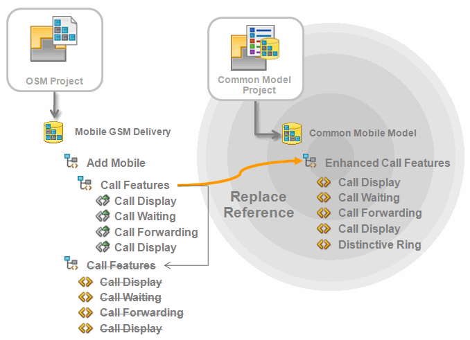
Description of "Figure 4-15 Refactoring Solutions Using Replace"
When you refactor solutions using the replace and resolve actions, Design Studio ensures that suitable substitutions are made and that the overall model integrity is maintained. For example, data element replacements must not break any data element references or introduce primitive type inconsistencies. Replacements must meet the following criteria:
-
Primitive types must match
-
Structure is a match or superset
-
Children of structures must be compatible
-
Proposed data elements are reusable
-
Replacement data element does not create an invalid recursion
-
Replacement data element does not reference the data element being replaced
-
Resolve action proposals are less specific
Working with Predefined Data Models
Predefined data models that are provided by Oracle Communications applications include product definitions to support your solution development. You can use predefined data models as the foundation for your new solutions, and build your own data models to extend and augment the predefined models.
There are two types of predefined data models: productized models and common models.
Productized models are predefined cartridges that you can use as the foundation for your new solutions. For example, Oracle Communications supports a library of extensible service activation cartridges that provide a basis from which to assemble services. You can purchase any of these cartridges, import them into Design Studio, and reuse them to create your own cartridge projects. Productized cartridges include configuration that supports product definitions.
The following common models might also be required by your Design Studio solution:
-
The Activation Routing model includes parameters required to support Design Studio for ASAP routing capabilities in a central schema. This model enables you to modify the routing support for each atomic action without requiring you to define the routing parameters. Design Studio adds this model to the workspace when you create an Activation project.
-
The Order Management Control Data model contains predefined simple data elements and structured data elements necessary for OSM order templates. For example, the ControlData structure is a reserved data area managed by decomposition and orchestration functions. When you create a new OSM project, Design Studio prompts you to add the model if it is not already present in the workspace.
-
The Activation Task Response model contains the Activation response parameters as sent from activation work order requests. You use the data in this model to map activation responses to the OSM task data. When you create a new Activation task in OSM, Design Studio prompts you to add this model if it is not already present in the workspace.
You are required to obtain and import the following common models if you are working with Design Studio for Inventory or Design Studio for Network Integrity:
-
The ora_uim_model common model is a read-only project that represents the UIM model. It supports the ability to define specifications and characteristics and is also used to validate which entity types can be assigned or referenced by configuration items.
-
The ora_uim_mds common model is a read-only project that represents the fields available displayed for entities in UIM. This project enables you to define the layout of fields in entities.
-
The NetworkIntegritySDK common model contains software components and libraries required for creating and extending Design Studio for Network Integrity cartridge projects.
Sharing Data Across Application Projects
When you design your fulfillment solution, you need to develop a model comprised of data for use in multiple applications. For example, you may want to create order templates, atomic actions, and service specifications, and share the data defined for those entities across your OSM, ASAP, Network Integrity, and UIM applications. Design Studio enables you to design integrated solutions that reduce occurrences of design errors when sharing data across applications.
About The Data Dictionary
The Data Dictionary is a logical collection of all data elements and types in a workspace. The Data Dictionary enables you to leverage common definitions across an entire Oracle Communications solution.
Design Studio projects are containers of entities, one of which is a data schema. You save all of your solution data in data schemas (all Design Studio features include data schemas). All data schemas in a workspace at any given time contribute to the Data Dictionary. Some Oracle Communications features enable you to create entities and data elements in specific editors, which are also included in the logical collection. You can review the Data Dictionary logical collection in the Dictionary view.
The Data Dictionary enables you to:
-
Integrate and correlate the data models for multiple applications.
-
Reduce the size and complexity of a solution model.
-
Simplify the application integration by eliminating data translation among applications.
-
Validate data model integrity.
About Data Leveraging
When modeling entities for your solution, you can use configuration from any other entity. Data modeling is not limited to using data elements within data schema entities. Any data configuration that contributes to the Data Dictionary is available for use.
The following sections provide examples of solution modeling using the Data Dictionary.
Example: Activation Leveraging Inventory Data
Figure 4-16 illustrates how an atomic action (Add GSM Subscriber), created in an Activation project, can be defined using the Caller ID, Call Waiting, and Call Forwarding data elements from a service specification created in an Inventory project.
Figure 4-16 Example: Activation Leveraging Inventory Data
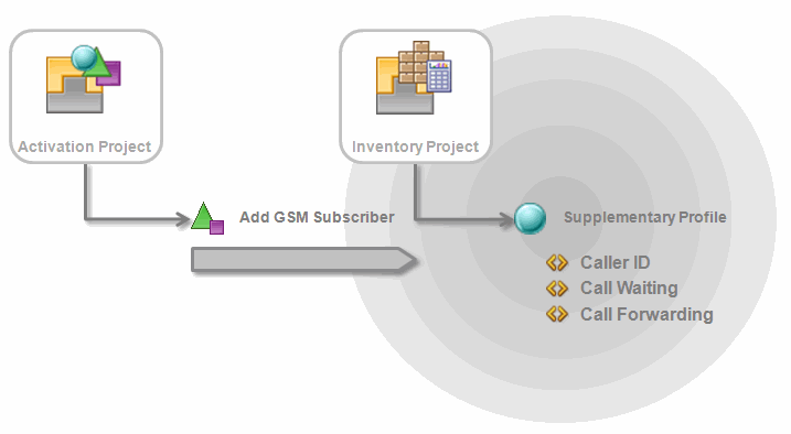
Description of "Figure 4-16 Example: Activation Leveraging Inventory Data"
Example: OSM Leveraging Activation Data
Figure 4-17 illustrates how an order (Mobile GSM Delivery) created in an OSM project can use the TN (telephone number) and TN Type (telephone number type) data elements from a service action modeled in an Activation project.
Figure 4-17 Example: OSM Leveraging Activation Data
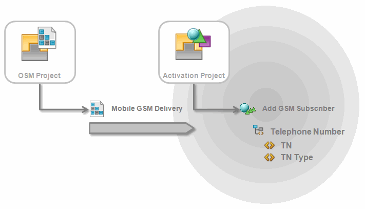
Description of "Figure 4-17 Example: OSM Leveraging Activation Data"
Example: OSM Leveraging Inventory Data
Figure 4-18 illustrates how an order (Mobile GSM Delivery) created in an OSM project can use the Caller ID, Call Waiting, and Call Forwarding data elements from a service specification modeled in an Inventory project.
Figure 4-18 Example: OSM Leveraging Inventory Data
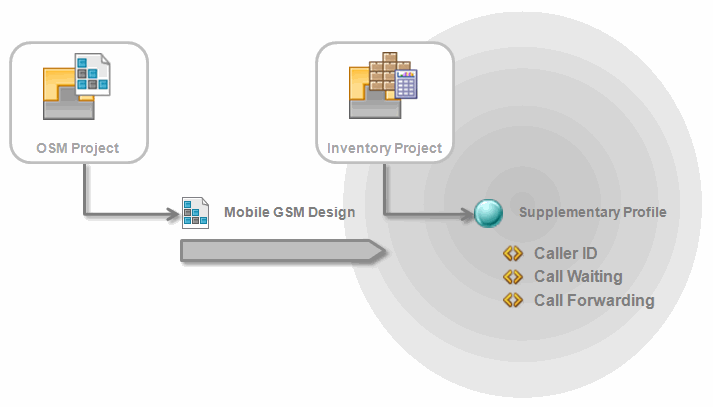
Description of "Figure 4-18 Example: OSM Leveraging Inventory Data"
