11 Equipment and Devices
This chapter describes how to define Equipment specifications in Oracle Communications Design Studio and how to use them to model your equipment in Oracle Communications Unified Inventory Management (UIM).
Understanding Equipment Modeling
In UIM, you can represent equipment in several ways. You can inventory all of your physical hardware resources down to the port level for asset-tracking purposes and you can represent your network elements as logical devices for activation purposes.
UIM enables you to capture the physical structure of your equipment visually. In Design Studio, you can create a prepopulated hierarchical view of your equipment that can be used in UIM to quickly create racks of populated equipment, or you can manually build out racks and shelves in UIM.
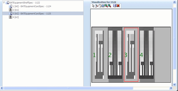
Figure 11-1 shows a shelf with four slots and two cards in UIM. When a module is selected in the tree view, the module is highlighted in the graphical view.
You can also choose to model your equipment logically. Modeling equipment logically enables you to create addressable network elements that can be managed or used with activation applications.
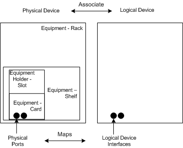
Figure 11-2 shows the physical and logical representations for a rack of equipment. The physical representation consists of racks, shelves, slots, cards, and ports and can be logically grouped into a physical device.
The logical representation consists of a logical device and logical device interfaces. You can associate a physical device to a logical device and map the physical ports to the logical device interfaces so that you can have addressable network elements while inventorying the physical equipment.
Figure 11-2 Physical and Logical Equipment Representations
Description of "Figure 11-2 Physical and Logical Equipment Representations"
Table 11-1 lists the equipment specifications used in Design Studio. Each of these specifications is described in this chapter.
Table 11-1 Equipment Specification Options
| Entity Specifications | Definitions |
|---|---|
|
Logical Device Device Interface Logical Device Account |
Groups equipment logically by function and enables you to create addressable network elements. |
|
Physical Device Physical Port Physical Connector |
Groups multiple pieces of physical equipment so that ports and connectors can be mapped to device interfaces. |
|
Equipment Equipment Holder Physical Port Physical Connector |
Inventories physical equipment, equipment holders, connectors, and ports. |
Understanding Logical Devices
A logical device represents a functional view of a set of resources. The logical device itself is not physical, but it can be supported by one or more physical resources that act together logically to perform one or more functions. Logical devices are understood at the network layer. They provide the ability to be discovered and can support service provisioning.
In the telecommunications industry, logical devices are often called network elements, but the terms are not interchangeable. In UIM, a logical device can also be a non-intelligent device that does not qualify as a network element.
Logical devices can be supported by one hardware item like a desktop router or by many pieces of hardware such as:
-
Central Office (CO) switches
-
Digital Cross-Connect Systems (DCSs)
-
Digital Subscriber Line Access Multiplexer (DSLAMs)
-
Main Distribution Frames (MDFs)
Logical devices can be associated with logical device accounts. For example, a voice mail server modeled as a logical device can be associated with logical device accounts that represent voice mail accounts. These associations are governed by associations between logical device and logical device account specifications. See "About Associating Logical Device Accounts with Logical Devices" for more information.
About Logical Device Hierarchies
Logical devices frequently include hierarchies of other logical devices and device interfaces. For example, a logical device entity that represents a router might include child logical device entities that represent virtual routers.
When you define a Logical Device specification, you can include specification relationships that you identify as Parent or Child. These specification relationships govern which logical devices you can add to logical device hierarchies:
-
If one or more specification relationships exist between logical device specifications, then only those relationships are valid for entities based on those specifications. No other logical devices can be included in that hierarchy. For example, if Logical Device Specification A has a Parent relationship with Logical Device Specification B, then the hierarchy of entities based on Logical Device Specification A can include only logical devices based on Logical Device Specification B.
-
If a logical device does not include any specification relations, its hierarchy can include any logical device that is not itself constrained by specification relationships.
Note:
In previous versions of UIM, specification relationships did not limit which logical devices could be included in a logical device hierarchy.
If you upgrade from a previous version to UIM 7.3 or later, existing specifications that include specification relationships govern hierarchies created after the upgrade. Existing hierarchies will not be affected unless you modify them. If you modify an existing hierarchy after upgrading, the changes are governed by the relationships defined in the affected specifications.
Understanding Device Interfaces and Sub-Interfaces
Logical devices can provide device interfaces. A device interface represents an access point into the device. These device interfaces may be for connectivity, power, timing, or any other means of access into or out of the device.
Some device interfaces correspond to physical ports while others are virtual. The virtual device interfaces are used for transmission (connectivity) purposes and are referred to as sub-interfaces. Device interfaces cannot exist on their own, but they are provided directly or indirectly by logical devices.
A device interface that represents a physical interface or port that can host a physical connection is called a media interface. A media interface must be the root interface in its device interface hierarchy.
You associate Device Interface specifications with Logical Device specifications and specify the minimum and maximum number of device interfaces that can be added to a logical device entity created based on a Logical Device specification.
For example, you can define a Logical Device specification that supports a minimum of 64 Local Area Network (LAN) ports. You can create these ports as device interfaces and specify the minimum quantity as 64. When a logical device based on this specification is created in UIM, 64 LAN ports are automatically created.
Similarly, you configure Device Interface specifications to determine which sub-interfaces they can include along with minimum and maximum quantities.
To create a logical device with device interfaces, perform the following high-level tasks:
-
Define a Logical Device specification for a device.
-
Define Device Interface specifications for the ports or other connectivity into the device.
-
On the Related Specifications tab for the Logical Device specification, relate the Device Interface specification.
-
Modify the properties of the related specification to add a minimum and maximum number of device interfaces to be created in UIM.
If the minimum quantity is not zero, the device interface is required; the minimum number of device interfaces are added automatically when you create a logical device or logical device interface. UIM prevents you from adding more than the specified maximum number of device interfaces, and you cannot remove device interfaces if it violates the minimum number required.
See the Design Studio Help for the steps to define specifications, associate related specifications, and modify relationship properties.
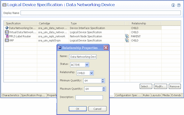
Figure 11-3 shows an example of a Logical Device specification for a Data Networking Device. On the Related Specifications tab, a Device Interface specification is selected. The relationship properties are set to a minimum of 64 and a maximum of 64.
Figure 11-3 DSLAM Logical Device Specification in Design Studio
Description of "Figure 11-3 DSLAM Logical Device Specification in Design Studio"
In UIM, when an entity is created based on the Data Networking Device specification, 64 device interfaces will be created based on the associated Device Interface specification. Because the maximum is set to 64, no additional device interfaces can be added to the logical device.
Associating Rate Codes to Device Interfaces
You can associate rate codes to device interfaces to define their bit rate and technology. The rate code associated to a device interface determines which connectivities can be terminated on the interface. See "About Termination" for more information. (Device interfaces with rate codes can also terminate Pipe entities. See "Configuring and Implementing Pipe Termination" for more information.)
For example, an OC1 rate code designates a 51.840 Mb/s SONET signal, while a DS3 rate code identifies a 44.736 Mb/s T-Carrier signal. See "About Rate Codes" for more information. Device interfaces with those rate codes can terminate only channelized connectivities with matching rate codes.
You associate rate codes with device interface specifications in Design Studio. When you create a device interface based on a specification with a rate code association, the rate code is automatically related to the interface.
The ora_uim_basetechnologies cartridge includes definitions of the supported rate codes. You must define this cartridge as a dependent cartridge for a project in Design Studio before you associate rate codes to device interface specifications. If you do not define the cartridge dependency, rate codes will not be available for selection when you define Device Interface specifications in Design Studio.
See UIM Cartridge Guide for more information about the base cartridge and see the Design Studio Help for more information about associating rate codes to device interface specifications.
About Interface-Bound Cross-Connects
Cross-connects are connectivity entities that participate in the continuity of end-to-end trail connectivity by interconnecting device interfaces within a logical device.
There are two kinds of cross-connects: interface-bound and trail-bound. Interface-bound cross-connects are bound to the life of the interfaces it connects and are created as part of their parent logical devices. See "About Interconnections" for more information.
For example, an interface-bound cross-connect could represent a D4 channel bank's multiplexing function, consisting of fixed internal connectivity from the 24 DS0 drop-side interfaces to the 24 DS0 line-side sub-interfaces provided by a high-speed DS1 line interface. (Line-side and drop-side refer to the high-speed and low-speed sides of a device.)
You create interface-bound cross-connects for device interfaces by selecting pairs of device interfaces in a logical device hierarchy. The device interfaces must have the same rate code. See the UIM Help for more information.
Cloning and Duplicating Logical Devices
You can clone and duplicate logical devices:
-
Duplicating the logical device copies only the entity itself. The duplicated entity is the same as the original except for the entity identifier.
-
Cloning the device copies the entity and (by default) all of its child logical devices, associated physical devices, and associated Equipment entities. By default, a cloned logical device is an exact copy of the original, aside from the entity identifier. You can customize the content of the clone.
By default, the following associations and mappings are copied when you clone a logical device:
-
Device interface hierarchy
-
Mapped physical devices
-
Equipment associations with physical devices
-
Mappings between device interfaces provided by the logical device and ports and connectors provided by physical devices and equipment
-
Cross-connects between device interfaces
You can customize the clone in the following ways:
-
Specifying names of logical device, physical device, and equipment created as part of the cloning operation
-
Assigning the cloned device to a different property location
-
Excluding specific items in the logical device hierarchy
-
Excluding specific physical device mappings and equipment associations
You can begin a logical device cloning operation from physical device search results. In this situation, the logical device associated to the physical device is cloned. If you want to copy only the physical device, you can use the existing Duplicate feature. Equipment entities associated to the physical device are not copied in this scenario, however.
See the UIM Help for more information about duplicating and cloning logical devices.
About Flow Interfaces
A flow interface is a point in a network through which traffic flows. You use flow interfaces to partition media interfaces (device interfaces at the top of their hierarchies) into virtual channels based on bit rate. Flow interfaces are similar to sub-device interfaces, but can have configurations that capture their attributes.
You use flow interfaces to terminate packet connectivity. They specify the termination type of the connectivities terminated on their parent device interfaces. There are four termination types defined by flow interface specifications:
-
Access. Indicates that the purpose of an interface is to terminate connectivity that provides access to a service provider network, such as Ethernet UNI connectivity.
-
Internetwork. Indicates that the purpose of an interface is to terminate connectivity that interconnects two service provider networks, such as Ethernet I-NNI connectivity.
-
Trunk. Indicates that the purpose of an interface is to terminate connectivity that connects equipment and devices in the same network.
-
Unknown. Indicates that the purpose of the interface is unknown.
Flow interface configurations can include references to flow identifiers (such as VLAN IDs) that trace the path of services through the device interfaces and connectivities in multipoint and point-to-point service arrangements. See "About Flow Identifiers" for more information. They can also include references to performance parameters such as bandwiidth profiles and class of service. These performance parameters are modeled in UIM with Custom Object entities. See "Performance Parameters" for more information.
A flow interface configuration is created automatically when you create a flow interface. As with other entities and entity configurations, you specify the flow interface configuration specification in the flow interface specification. Unlike other entities, however, flow interface specifications can be associated with only one configuration specification.
You cannot create flow interfaces directly from the logical device or device interface hierarchy in a Summary page. Rather, you create them in the packet virtual networks that include them. See UIM Help for more information about creating flow interfaces.
Logical Device Configurations
A logical device configuration contains information about how the device is realized in terms of resources that are assigned to it. Logical device configuration items can assign or reference resources such as:
-
Custom network addresses
-
Custom objects
-
Device interfaces
Typically, logical device configurations consume device interfaces that are on a different logical device. Logical devices can consume a network address that can change over time. For example, this could be a route distinguisher address type.
See "Configurations" for more information about configuration specifications.
Understanding Logical Device Accounts
Logical device accounts are a special type of network address that are hosted or managed by a logical device. You can associate logical device accounts to logical devices. For example, email account IDs are considered unique to an email domain, typically managed by a logical domain device. For a mobile wireless service, you can create a logical device account for a subscriber on the Home Location Register (HLR) and Voice Messaging System (VMS). Accounts for accessing content on online music or IPTV servers could also be modeled this way. For a service provider, a logical device account could be a management account, such as a login name for configuring a logical device.
Other examples of logical device accounts include:
-
Instant messaging (IM) accounts
-
RADIUS AAA accounts
-
Voice mail (VM) accounts
-
Element management accounts
You use Logical Device Account specifications to define these accounts in your inventory. The information captured in a Logical Device Account specification depends on the account that you are modeling. For example, you might need to add characteristics for subscriber information such as a login name, mailbox, or accounting record.
About Logical Device Account Configurations
Logical Device Account entities can have configurations. You can use logical device account configurations to maintain a history of subscriber details. For example, subscriber details for a GSM customer can be stored in a logical device account related to a Home Subscriber Server (HSS). As the subscriber details evolve over time, you can use configurations to maintain a history for auditing and validation.
Only telephone numbers and custom network addresses can be assigned to configuration items in Logical Device Account configurations. You can include references to all reference-enabled entities, however.
See "Configurations" for more information about how you use configurations.
About Associating Logical Device Accounts with Logical Devices
You can create associations between logical devices and logical device accounts. For example, you can create an association between a voice mail account (a logical device account) and a voice mail server (a logical device).
When you define Logical Device specifications, you can include Parent specification relationships to Logical Device Account specifications. Similarly, when you define Logical Device Account specifications, you can include Child specification relationships to Logical Device specifications. See Design Studio Help for more information about creating specification relationships.
In UIM, these specification relationships govern which logical devices and logical device accounts you can associate with each other.
-
If one or more specification relationships exist between logical device and logical device account specifications, then only associations based on those relationships are valid. For example, if Logical Device Specification Y has a Parent relationship with Logical Device Account Specification Z, then you can make associations only between entities that are based on these specifications. You cannot make associations between the logical devices based on Logical Device Specification Y and logical device accounts based on any specification other than Logical Device Account Specification Z.
-
If a Logical Device or Logical Device Account specification has no specification relationships, you can create associations freely.
Note:
In releases previous to UIM 7.3, specification relationships did not limit which logical devices and logical device accounts could be associated with each other.
If you upgrade from a previous version to UIM 7.3 or later, existing specifications that include specification relationships govern associations created after the upgrade. Existing associations will not be affected unless you modify them.
Understanding Physical Resources
Your inventory is likely to include physical hardware items such as routers, DSLAMs, interface cards, and so on. To enable you to manage these resources in your inventory, UIM includes several different types of physical resource specifications:
-
Physical Devices: A physical device is a collection of hardware resources that have a common function in the network. It is the physical equivalent to a logical device. This is required to map physical equipment to logical devices.
-
Equipment: Equipment refers to physical units of equipment such as racks, shelves, circuit cards, field-replaceable units (FRUs), or handheld phones.
-
Equipment Holders: Equipment holders are slots or mounting positions that contain cards.
-
Physical Ports: Physical ports are the places where communication begins or ends on a physical device or equipment.
-
Physical Connectors: Physical connectors connect hardware units for signal or power transmission.
You configure these specifications and the entities based on them to reflect the physical resource composition of your inventory.
Configuring Equipment Specifications
Equipment specifications represent physical items of hardware such as racks, shelves, and cards. Shelves can provide slots (modeled with the Equipment Holder specification) that hold cards or modules. Equipment specifications can also model self-contained, independent devices such as routers or desktop modules.
You can model your equipment visually in Design Studio so that it is automatically built out in UIM or you can define the individual Equipment specifications and manually build out your equipment in UIM. This section describes how to build out your equipment specifications in Design Studio so that equipment is automatically built in UIM.
Understanding the Visualization Tab
The equipment category you choose for the equipment specification determines what appears in the Visualization tab. You can select card, shelf, rack, or leave the equipment category blank.
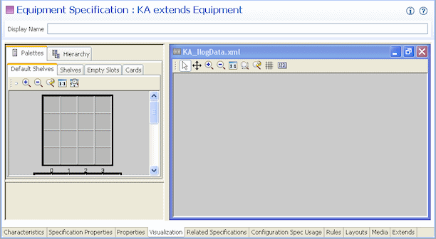
Figure 11-4 shows the Visualization tab for a shelf specification.
The Visualization tab includes several areas that you work in:
-
The Palettes tab contains templates that you use to define the basic structure of the equipment. You drag items from the Palettes tab to the canvas. The Palettes tab contains subtabs that are based on whether the Equipment specification is defined as a card, a rack, or a shelf.
-
The canvas is the area where you configure the equipment by dragging items from the Palettes tab.
-
The Hierarchy tab displays the equipment configuration in tree-view form. It reflects the content of the canvas and is updated when you add new items. When you select an item in the canvas, the corresponding item in the tree view is highlighted. When you select an item in the tree view, the corresponding item in the canvas is highlighted.
Typically the easiest way to build your equipment is to start at the equipment holder and work your way up to cards, shelves, and racks. Model your equipment holders first, then your cards. Create shelves using the existing cards and finally add racks using existing shelves of equipment holders and cards.
You can choose to model the ports and connectors at any time because they are not done through visualization tabs. See "Adding Ports and Connectors" for more information.
Configuring Equipment Holder Specifications
An Equipment Holder specification defines a slot into which cards can be installed. The holder itself does no processing. Equipment holders are provided by equipment and can contain other equipment. For example, a shelf provides an equipment holder. A LAN card can be installed into the equipment holder.
You can limit the cards that slot can contain by creating a parent-to-child relationship between its Equipment Holder specification and one or more Card specifications. In UIM, slots based on the Equipment Holder specification can contain only cards with which it has a child relationship.
Note:
In some cases, an Equipment Holder specification can be a child of a Card specification rather than the reverse. In this situation, UIM does not limit the cards that slots based on the Equipment Holder specification can contain.
Configuring Card Specifications
When you configure a card specification, you assign a template that determines the card's orientation. You can choose a vertical or horizontal orientation. You also determine how many holders the card requires. This number determines how many contiguous slots are required when you add the card to a shelf.
Note:
You must configure a card specification in the Visualization tab before it can be added to shelves.
Configuring a Shelf Specification
When you configure a shelf specification, you define the shelf arrangement by choosing a template or by using an existing shelf. You then add card specifications or empty slot specifications to the shelf.
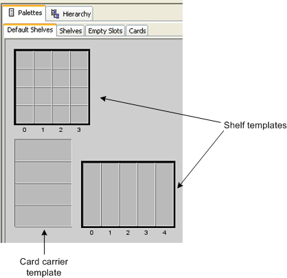
There are two default templates: shelf and card carrier. The shelf template creates a shelf. You can change the number of rows and columns. The card carrier template can be placed on a shelf template to visually change the layout of the shelf when cards need to be grouped in ways that cannot be changed by changing the rows and columns.
Figure 11-5 shows the two shelf templates and the card carrier template.
When you have completed the shelf and card carrier visualization, you can add card specifications and Equipment Holder specifications. When you add a card specification to the shelf, you specify the slot it will occupy and the Equipment Holder specification. If the card specification requires more than one holder, the shelf must have enough contiguous slots beginning with the selected slot.
In UIM, when you create a new shelf entity, it is prepopulated with the cards defined in its specification. You can see the equipment in the Equipment visualization. See the UIM Help for more information about the Equipment visualization.
Configuring a Rack Specification
A rack includes one or more shelves. You can include any of the shelves that have already been defined in the workspace.
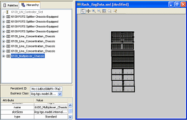
Figure 11-6 shows an Equipment specification for a rack. The Palettes tab lists all available Equipment specifications for shelves, and the Hierarchy tab shows the racks visualized in the canvas. In this case, various shelves were dragged from the Palettes tab to the canvas to create a shelf visualization.
Adding Ports and Connectors
In Design Studio, you can configure an Equipment specification so that entities based on it automatically include physical ports and physical connectors. You must define Physical Port specifications and Physical Connector specifications in Design Studio and then relate them to an Equipment specification on the Related Specifications tab. Physical connectors and physical ports cannot exist on their own, but they are provided by equipment or physical devices.
Note:
Ports and connectors are not shown on the visual canvas in Design Studio or UIM.
For example, you can associate a Physical Port specification for a LAN port to an Equipment specification for a LAN interface card. Because equipment typically has a fixed number of ports and connectors, the minimum and maximum quantity would be the same. The minimum quantity of ports or physical connectors is automatically added to the equipment when an equipment entity is created based on the Equipment specification related to Physical Port or Physical Connector specifications.
In UIM, you can add physical connectors and physical ports to equipment and physical devices. You can also remove connectors and ports. You maintain these associations for equipment using the tree view. You maintain them on physical devices using the Physical Device Summary page.
In the Physical Device Hierarchy section of a Physical Device Summary page, you can see information about the assignment status, conditions, and consumer of a physical port. You can follow a link to go to the Summary page of the consuming entity. For example, if the port is assigned to a configuration item in a Service configuration, the parent service is shown as a link in the tree view. See the UIM Help for more information.
Configuring Physical Port Specifications
A Physical Port specification defines a point of entry for communication. A physical port is where communication begins or ends on a physical device or unit of equipment. Unlike a physical connector, a physical port performs basic processing, such as reading transmission data.
Physical ports are provided by physical devices or equipment such as chassis or cards. For example, a LAN port could be provided by a LAN interface card.
The following are examples of physical ports that can be defined with Physical Port specifications:
-
T1/E1 port
-
LAN port
-
Switch port
-
DSLAM port
Configuring Physical Connector Specifications
You use Physical Connector specifications to model hardware that physically links or connects hardware units for the transmission of signals or power. Unlike physical ports, physical connectors have no built-in intelligence; they simply conduct a signal. Examples include:
-
RJ-45 network connector
-
MDF terminal block connector
-
DB-36 connector
Manually Configuring Equipment in UIM
If you do not build out racks or equipment in Design Studio, you can build your equipment out manually in UIM. You can also add multiple equipment entities at a time in UIM by using the Equipment Range link. See the UIM Help for more information about adding equipment.
In UIM, you can create new equipment and use the tree view to add child equipment. For example, you can create a new shelf and add cards to the shelf.
Configuring Physical Device Specifications
Physical devices are aggregations of physical resources that can include other physical devices and equipment. For example, a physical device can represent a DSLAM that includes one or more multiplexers and splitters. Physical devices can be related hierarchically.
In UIM, you can associate a physical device to a corresponding logical device. When that association is complete, you can map the ports and connectors provided by the physical device or by the equipment associated with the physical device to the device interfaces in a logical device.
In Design Studio, you can include Physical Port and Physical Connector specifications in the Related Specifications tab of a Physical Device specification. Making these associations means that ports and connectors are included automatically in UIM when physical devices are created. See "Adding Ports and Connectors" for more information. In most cases, however, physical ports and connectors are configured with equipment and not with physical devices.
Associating Physical Devices to Logical Devices
A physical device can be associated to one logical device, but a logical device can be associated to one or more physical devices. When a physical device is associated to a logical device, you can map the device interfaces to the physical connectors or ports on the physical device or to the physical ports and connectors of equipment related to the physical device. You can also map the ports and connectors of equipment that is down the hierarchy of the equipment associated to the physical device.
Only top-level device interfaces can be mapped. A device interface can be mapped to multiple ports and connector, but ports and connectors can be mapped to only one device interface. Device sub-interfaces cannot be mapped.
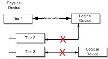
You can associate logical and physical devices at only one tier in the hierarchy. See Figure 11-7 for an example of associations. In this example, a tier 1 physical device is associated to a logical device; therefore, the tier 2 physical devices are not available for association to logical devices.
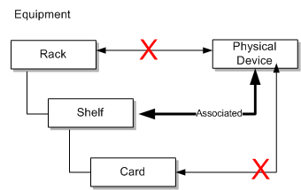
You can associate equipment within a physical device at only one tier within the hierarchy. See Figure 11-8 for an example. In this example, a shelf (tier 2) in a rack is associated with a physical device; therefore, associations cannot be made at the rack (tier 1) or card (tier 3) level.
You can map device interfaces to ports or connectors provided by equipment or physical devices either automatically or manually. See the UIM Help for information about mapping device interfaces to ports and connectors.
Associating Devices and Equipment with Network Locations
You can define the locations of logical devices, physical devices, and Equipment entities by associating them with network locations. A network location is a Property Location entity that has been assigned a network location code. See "Property Locations" for more information.
Network locations are used in modeling channelized connectivity only. The network location associated to a logical device, physical device, or Equipment entity identifies the property location where the entity is physically located.
Note:
Property Location entities are similar to but not the same as Place entities. You can associate a logical device to Place entities to define other kinds of location-oriented relationships, such as the place where the device is managed.
You can associate the network locations directly to the entities. The associations can also be made automatically as the result of propagation downward through hierarchies. See "Understanding Network Location Code Propagation" for more information.
Associating Logical Devices with Network Locations and Network Entity Locations
A logical device that is located at a property location is known as a network device and it can terminate channelized connectivity. See "About Termination" for more information.
Unlike physical devices or Equipment entities, you can associate logical devices with network locations or network entity codes. Network entity codes are used to identify devices that can enable services at a network location. A network location can be associated with more than one logical device, but a network entity code can be associated with only a single logical device.
Typically, network entity codes are applied to logical devices that are managed by a network management system (NMS) and that require some configuration to enable services.
A network entity code is always displayed in combination with the network location code of its related network location and is referred to as a network entity location. See "About Network Locations" for more information.
When network entity codes have been defined for a network location, you see them in the list you use to associate a network location to a logical device. For example, if network location PLANTXUSXA includes a single network entity code (K01) and network location PLANTXUSXB includes two network entity codes (K01 and K02), you see the following choices when you select a network location for a logical device.
- PLANTXUSXA
- PLANTXUSXA.K01
- PLANTXUSXB
- PLANTXUSXB.K01
- PLANTXUSXB.K02
The list excludes network entity location codes that have already been associated to logical devices.
Note:
Network entity codes are optional and are typically not used for devices that do not require activation or management.
When you select a network location, UIM sets a default device identifier that depends on the network location you select:
-
If you select a network entity location code, such as PLANTXUSXB.K01, the device identifier is set to that value.
-
If you select only a network location code, such as PLANTXUSXB, the device identifier is set to the network location followed by a sequential number in parentheses. This pattern enables all devices located at the network location without a network entity code to default to a unique device identifier. For example, the first default device identifier for PLANTXUSXB is PLANTXUSXB (1).
In either case, you can change the device identifier supplied by UIM with one that corresponds to your business practices. The identifier must be unique across all logical devices.
See the UIM Help for more information about selecting network locations and setting device identifiers.
Associating Equipment and Physical Device Entities with Network Locations
You can define the location of an Equipment entity or physical device by associating it with a network location (a Property Location entity that has been assigned a network location code). There are three ways in which these entities can be associated with network locations:
-
By associating a Physical Device or Equipment entity with a logical device that has a network or network entity code or with a logical device in the hierarchy of a parent logical device with such a code.
-
By specifying a network location code when you create the entity. A Network Location field now appears in the Create page for Equipment and Physical Device entities.
-
By editing a Equipment or Physical Device entity to include a network code. A Network Location field appears in the Information page that you see when you edit entities of these types.
Understanding Network Location Code Propagation
Network location codes are propagated downward through physical device and equipment hierarchies. The highest-level entity that has a network location code is the location parent for the hierarchy.
Note:
Equipment and Physical Device entities cannot be assigned network entity codes. Network entity codes are valid only for logical devices.
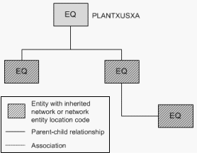
Because equipment hierarchies can include only other Equipment entities, the propagation of network location codes is straightforward. All Equipment entities below the location parent are assigned the network location code assigned to the parent. You cannot change these codes for the child entities unless you also change the code for the parent.
Figure 11-9 illustrates a small Equipment hierarchy. All the entities have the network code PLANTXUSXA.
Figure 11-9 Network Location Code for Equipment Hierarchy
Description of "Figure 11-9 Network Location Code for Equipment Hierarchy"
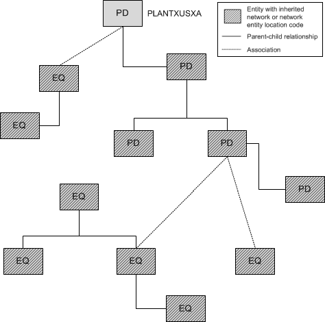
Physical device hierarchies can include other physical devices. In addition, physical devices can be associated with Equipment entities. In this kind of hierarchy, all physical devices in the hierarchy and all Equipment entities associated with physical devices in the hierarchy are automatically assigned the network location code of the parent physical device. You cannot change the automatically assigned network location codes.
Figure 11-10 illustrates a physical device hierarchy in which physical devices are associated with Equipment entities. All of the entities in this hierarchy are assigned the PLANTXUSXA network code of the parent physical device.
Figure 11-10 Network Location Code Physical Device Hierarchy
Description of "Figure 11-10 Network Location Code Physical Device Hierarchy"
Logical device hierarchies can be complex because logical devices can be associated with physical devices, which in turn can be associated with Equipment entities. In addition, logical devices can have network location codes or network entity location codes.
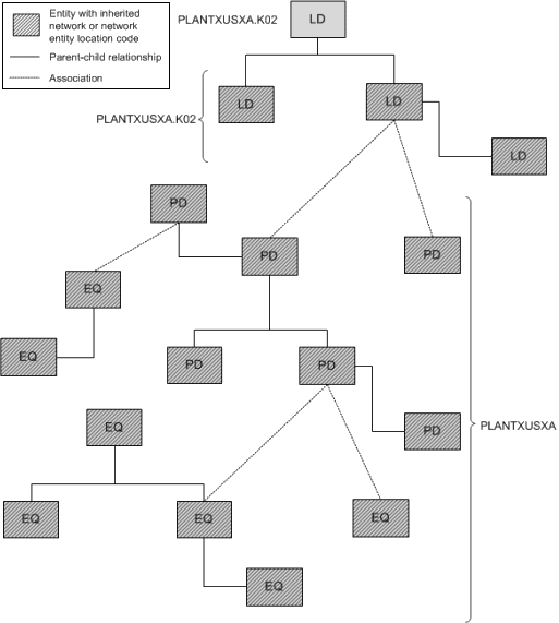
In a logical device hierarchy, child logical devices inherit the network location code or network entity location code of the parent logical device. Physical devices and Equipment entities inherit only the network location code.
In the hierarchy shown in Figure 11-11, the logical devices have inherited the parent logical device's network entity location code (PLANTXUSXA.K02). Physical devices associated with logical devices in the hierarchy inherit only the network location code (PLANTXUSXA). You cannot change any of the automatically assigned network location or network entity location codes.
Figure 11-11 Network and Network Entity Location Codes for Logical Device Hierarchy
Description of "Figure 11-11 Network and Network Entity Location Codes for Logical Device Hierarchy"
Network location associations to Equipment and Physical Device entities cannot be made if the association currently or potentially conflicts with a network location association. The conflict does not necessarily have to be direct: it can result from associations related to hierarchies in which the entity participates.
For example, you cannot directly assign a network location code to an Equipment entity that is associated to a physical device that has inherited a network location from a parent physical device. In this situation, the Equipment entity already has a network location code that it inherits from the associated physical device.
Similarly, you cannot remove or change an inherited network location or network entity location code without either removing the entity in question from its hierarchy or association. Alternatively, you can change or remove the network location or network entity location code from the location parent entity. Removing or changing that code removes or changes it in all entities that have inherited it.
