Front Panel Components

The following figure shows the Oracle Exadata Database Server X8-8 chassis front panel components:
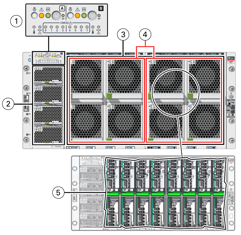

An illustration showing the front of the system with components.

Call Out Component Link

1

Front indicator module (FIM).

  • Chassis/SMOD0 System A controls and indicators:

    Locate Button/LED: white

    Fault-Service Required LED: amber

    System OK LED indicator: green

    On/Standby button, recessed

    SP OK: green

    System Overtemperature Warning LED: amber

    Chassis SMOD0 Rear Fault-Service Required LED: amber

    CMOD0-3 Fault-Service Required LEDs 0, 1, 2, 3: amber

  • SMOD1 System B controls and indicators:

    Locate Button/LED: white

    Fault-Service Required LED: amber

    System OK indicator: green

    On/Standby button, recessed

    SP OK: green

    System Overtemperature Warning LED: amber

    SMOD1 Rear Fault-Service Required LED: amber

    CMOD4-7 Fault-Service Required LEDs 4, 5, 6, 7: amber

Front Indicator Module (FIM) Panel

Controls and Indicators

2

Four power supplies (PS)

Power supplies 0 (bottom) through 3 (top) labeled PS0, PS1, PS2, PS3

PS2 and PS3 power System A. PS0 and PS1 power System B.

Power Supply (PS) Indicators

Power Subsystem

3

Eight fan modules (FM)

Fan modules FM0 through FM7: Top row: 1, 3, 5, 7 Bottom row: 0, 2, 4, 6

SMOD0 System A: FM 0, 1, 2, 3; SMOD1 System B: FM 4, 5, 6, 7

Troubleshooting System Cooling Issues

Cooling Subsystem

4

Two fan frames

SMOD0 System A: FM 0, 1, 2, 3; SMOD1 System B: FM 4, 5, 6, 7

Troubleshooting System Cooling Issues

Cooling Subsystem

5

Eight internal CPU Modules (CMODs). CMOD bays are accessible behind the fan frames.

8-socket mode: CMODs 0-7

CPU Module (CMOD) Overview

For component serviceability, locations, and designations, see Replaceable Components.