Overview of the Oracle ZFS Storage ZS3-2 Controller
This section provides an overview of the Oracle ZFS Storage ZS3-2 controller. For installation instructions, refer to Installing an Oracle ZFS Storage ZS3-2 Controller. For service instructions, refer to Servicing the Oracle ZFS Storage ZS3-2 Controller in Oracle ZFS Storage Appliance Customer Service Manual, Release OS8.8.x.
Oracle ZFS Storage ZS3-2 Physical Specifications
The Oracle ZFS Storage ZS3-2 controller 2U chassis dimensions are as follows:
| Dimension | Measurement | Dimension | Measurement |
|---|---|---|---|
|
Height |
3.44 in./87.4 mm |
Depth |
20.25 in./514 mm |
|
Width |
17.52 in./445 mm |
Weight |
41.23 lb/18.70 kg |
Oracle ZFS Storage ZS3-2 Electrical Specifications
The Oracle ZFS Storage ZS3-2 controller electrical specifications are listed below. The power dissipation numbers listed are the maximum rated power numbers for the power supply. The numbers are not a rating of the actual power consumption of the appliance.
Connectors
-
Two C13 connectors, which work on 110-220v outlets
Input
-
Nominal frequencies: 50/60Hz (47 to 63 Hz range)
-
Nominal voltage range: 100 to 120/200 to 240 VAC
-
Maximum current AC RMS: 6.8 A @ 100-120 V / 3.4 A @ 200-240 V
-
AC operating range: 90-264 VAC
Output
-
3.3 VDC STBY: 3.0A
-
+12 VDC: 86.7A
Power Dissipation
-
Max power consumption: 890 W max
-
Max heat output: 3026 BTU/hr
-
Volt-Ampere rating: 908 VA @ 240 VAC, 0.98P.F.
Oracle ZFS Storage ZS3-2 Acoustic Noise Emissions
In compliance with the requirements defined in ISO 7779, the workplace-dependent noise level of this product is less than 70 db (A).
Oracle ZFS Storage ZS3-2 Configuration Options
The Oracle ZFS Storage ZS3-2 controller is an enterprise-class, rackmount x86 system powered by the Intel Xeon processor. It provides high performance and room for growth with expandable PCIe slots and 16 DIMM slots in a compact 2U footprint. The following table describes the configuration options.
| CPU | Memory | Readzilla | Boot Drive | PCIe Slots | HBA |
|---|---|---|---|---|---|
|
2x8-core, 2.1GHz |
256GB 16x16GB 512GB 16x32GB |
1-4 SAS SSDs |
Two 2.5-inch SAS HDDs |
Two dedicated; four available |
4-port (4x4) SAS-3 12Gb/s external 4-port (4x4) SAS-2 6Gb/s external |
Refer to https://oracle.com/zfsstorage for the most recent component specification.
Oracle ZFS Storage ZS3-2 Front Panel Components
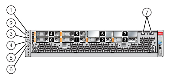
The Oracle ZFS Storage ZS3-2 controller drive slots and front panel components are shown in the following figure.

Drive slots 0 and 1 have two mirrored SAS-2 boot drives. Up to four read cache SSDs fill slots 2 through 5, in order. Slots 6 and 7 are empty and must contain drive fillers.
|
1 Locator LED/button (white) |
2 Service Action Required LED (amber) |
3 Power OK LED (green) |
|
4 Power button |
5 Service Processor OK LED (green) |
6 Fan/CPU/Memory Service Required LED |
|
7 USB 2.0 ports |
Note:
The LEDs below the Fan/CPU/Memory Service Required LED are not currently used.Oracle ZFS Storage ZS3-2 Rear Panel Components
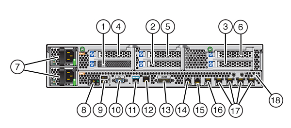
The Oracle ZFS Storage ZS3-2 controller PCIe slots and rear panel components are shown in the following figure.
For more information about PCIe cards, see Oracle ZFS Storage ZS3-2 PCIe I/O Cards in Oracle ZFS Storage Appliance Customer Service Manual, Release OS8.8.x.

|
1 SAS-2 internal HBA (slot 1) |
2 4x4 SAS external HBA (slot 2) |
3 PCIe slot 3 |
|
4 PCIe slot 4 |
5 PCIe slot 5 |
6 PCIe slot 6 |
|
7 AC power supplies PS1 (top), PS0 (bottom) |
8 System status LEDs |
9 USB 2.0 ports |
|
10 SP 15-pin VGA video port |
11 Serial management port |
12 Network management (NET MGT) 10/100 BASE-T Ethernet port |
|
13 Alarm port, DB-15 connector (not used for the ZS3-2) |
14-16 Cluster I/O ports |
17 10-Gbit Ethernet ports |
|
18 Chassis ground post |
Note:
The three Cluster I/O ports (0, 1, and GigE) are reserved for cluster interconnection only.The Oracle ZFS Storage ZS3-2 controller has the following ports:
-
Ethernet Ports - Oracle ZFS Storage ZS3-2 has four RJ-45 10-Gigabit Ethernet (10GbE) network connectors, labeled NET 3, NET 2, NET 1, and NET 0 (left to right) on the rear panel. The ports operate at 100 Mbits/sec, 1000 Mbits/sec, or 10-Gbits/sec. Use these ports to connect the appliance to the network.

The LEDs located above each NET port are Link/Activity (left) and Speed (right) indicators for each port as described in this table:
Connection Type
EEE Terminology
Speed LED Color
Transfer Rate
Fast Ethernet
100BASE-TX
Off
100 Mbits/sec
Gigabit Ethernet
1000BASE-T
Amber
1000 Mbits/sec
10 Gigabit Ethernet
10GBASE-T
Green
10000 Mbits/sec
-
Cluster I/O Ports - Two cluster serial ports (0 and 1) and one Ethernet port provide communication between two controllers to form a cluster configuration. For information about how to connect cables to form a cluster, see Connecting Disk Shelf Cables.

Caution:
When disconnecting an RJ-45 cable from a cluster serial port (0 and 1), use extreme care not to damage the internal RJ-45 receptacle. To properly disconnect an RJ-45 cable from a cluster serial port, see Disconnecting an RJ-45 Cable. -
Network Management Port - The network management connector (NET MGT) is an RJ-45 10/100 BASE-T Ethernet port and provides an alternate terminal interface to the SP console.

-
Serial Management Port - The serial management connector (SER MGT) is an RJ-45 port and provides a terminal connection to the service processor (SP) console.

-
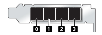
HBA Ports - The 4x4 SAS HBA, installed in PCIe slot 2 of the ZS3-2, provides connectivity to external disk shelves. The HBA logical ports are numbered 0-3, left to right, as shown in the following illustration:

Optional Cable Management Arm
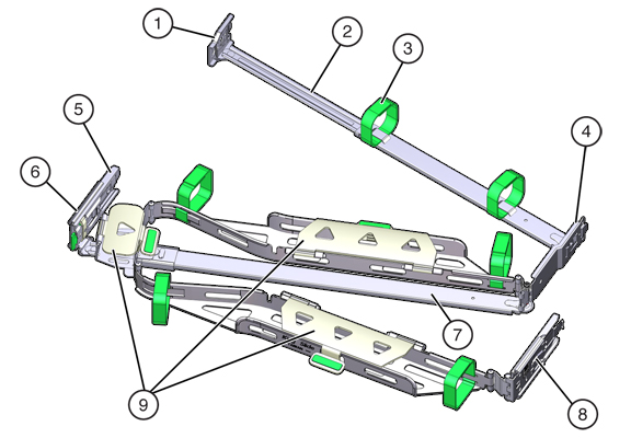
The following figure identifies the components of the second-generation cable management arm (CMA). See the CMA installation instructions.

|
1 Connector A |
2 Front slide bar |
3 Velcro straps (6) |
|
4 Connector B |
5 Connector C |
6 Connector D |
|
7 Slide-rail latching bracket (used with connector D) |
8 Rear slide bar |
9 Cable covers |