Overview of the Sun ZFS Storage 7420 Controller
This section provides an overview of the Sun ZFS Storage 7420 controller. For installation instructions, refer to Installing a Sun ZFS Storage 7x20 Controller. For service instructions, refer to Servicing the Sun ZFS Storage 7x20 Controller in Oracle ZFS Storage Appliance Customer Service Manual, Release OS8.8.x.
Sun ZFS Storage 7420 Physical Specifications
The Sun ZFS Storage 7420 controller 3U chassis dimensions are as follows:
| Dimension | Measurement | Dimension | Measurement |
|---|---|---|---|
|
Height |
13.3 cm/5.25 in |
Depth |
70.6 cm/27.8 in |
|
Width |
43.7 cm/17.19 in |
Weight |
16.36 kg/96 lbs |
Sun ZFS Storage 7420 Electrical Specifications
The following list shows the electrical specifications for the Sun ZFS Storage 7420 controller.
Note:
The power dissipation numbers listed are the maximum rated for the power supply and are not a rating of the actual power consumption of the appliance.Input
-
Nominal frequencies: 50/60Hz
-
AC operating range: 100-127 VAC for 2 CPUs and 200-240 VAC for 2 or 4 CPUs
-
Maximum current AC RMS: 12A @ 100 VAC / 12A @ 200 VAC
Power Dissipation
-
Max power consumption: 1800 W
-
Max heat output: 6143 BTU/hr
-
Volt-Ampere rating: 1837 VA @ 240 VAC, 0.98 P.F.
Sun ZFS Storage 7420 Configuration Options
The Sun ZFS Storage 7420 consists of a standalone storage controller, or two storage controllers in a high-availability cluster configuration, and one to 36 disk shelves. The following table describes the Sun ZFS Storage 7420 configuration options:
Note:
Sun ZFS Storage 7420 M2 controllers cannot be clustered with Sun ZFS Storage 7420 controllers.| Product ID | CPU | DIMMs | Readzilla | Boot Drive |
|---|---|---|---|---|
|
Sun ZFS Storage 7420 M2 |
4x8-core, 2.0GHz |
8GB, 16GB |
1.6TB SAS |
900GB SAS |
|
Sun ZFS Storage 7420 M2 |
4x10-core, 2.40GHz |
8GB, 16GB |
1.6TB SAS |
900GB SAS |
|
Sun ZFS Storage 7420 |
4x8-core, 2.0GHz |
8GB, 16GB |
512GB SATA |
500GB SATA |
|
Sun ZFS Storage 7420 |
4x10-core, 2.40GHz |
8GB, 16GB |
512GB SATA |
500GB SATA |
You can identify your configuration by looking at the product ID on BUI screen Maintenance or by using the CLI command configuration version show. You can also check the physical label on the boot drive.
Refer to https://oracle.com/zfsstorage for the most recent component specification.
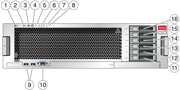
Sun ZFS Storage 7420 Front Panel Components

|
1 Locator LED and button (white) |
2 Service Required LED (amber) |
3 Power/OK LED (green) |
|
4 Power button |
5 Service Processor (SP) OK LED (green) |
6 Fan/CPU/Memory Service Required LED |
|
7 Power Supply (PS) Service Required LED |
8 Over Temperature Warning LED |
9 USB 2.0 Connectors |
|
10 DB-15 video connector |
11 Boot drive 0 (mirrored) |
12 Boot drive 1 (mirrored) |
|
13 SSD 2 (optional) |
14 SSD 3 (optional) |
15 SSD 4 (optional) |
|
16 SSD 5 (optional) |
The Sun ZFS Storage 7420 M2 controller has two SAS-2 system boot drives in slots 0 and 1, configured as a mirrored pair. Up to four SAS-2 read cache SSDs may fill slots 2 through 5, in order. In a Sun ZFS Storage 7420 M2 cluster, the number of SSDs installed in each controller can vary.
Sun ZFS Storage 7420 controllers have two SATA system boot drives in slots 0 and 1, configured as a mirrored pair. Zero, two, three, or four read cache SSDs, may optionally fill slots 2 through 5, in order. In a Sun ZFS Storage 7420 cluster, the number of SSDs installed in both controllers must match.
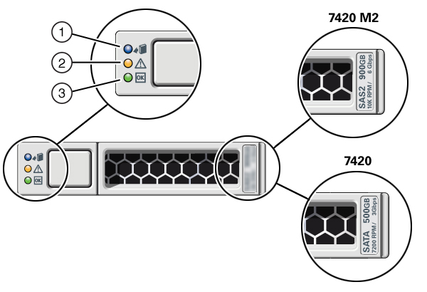
SAS-2 and SATA Boot Drive LEDs

|
1 Ready to remove (blue) |
2 Service action required (amber) |
3 OK/Activity (green) |
Sun ZFS Storage 7420 Rear Panel Components
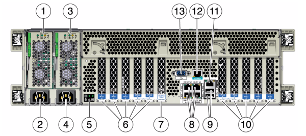
The following graphic shows the rear panel of the controller. Base configuration HBAs are not depicted in this illustration.
For information about PCIe cards, see Sun ZFS Storage 7420 PCIe I/O Cards in Oracle ZFS Storage Appliance Customer Service Manual, Release OS8.8.x.

|
1 Power supply unit 0 status LEDs OK: green Power Supply Fail: amber AC OK: green |
2 Power supply unit 0 AC inlet |
3 Power supply unit 1 status LEDs OK: green Power Supply Fail: amber AC OK: green |
|
4 Power supply unit 1 AC inlet |
5 System status LEDs Power: green Attention: amber Locate: white |
6 PCIe slots 0-4 |
|
7 Cluster card slot |
8 Network (NET) 10/100/1000 ports: NET 0-NET 3 |
9 USB 2.0 ports |
|
10 PCIe slots 5-9 |
11 Network management (NET MGT) 10/100 BASE-T Ethernet port |
12 Serial management (SER MGT) port |
|
13 DB-15 video connector |