C H A P T E R  5

Maintenance Tasks

This chapter describes some of the maintenance tasks that you might need to perform periodically on the Sun StorEdge S1 array.

This appendix is organized as follows:


Powering Off the Array


caution icon

Caution - Before turning off the host's system power, exit from the operating system. Failure to do so might cause data loss.


procedure icon  To Power Off the Array

1. If necessary, notify users that the host system is going to be shut down.

2. Back up system files and data, if necessary.

3. Halt the operating system.

4. Press the power system switch on the array to the standby position.


caution icon

Caution - Even with the power switch in the standby position, power remains connected to the array, and potentially dangerous voltage is present in the power supply. You must disconnect the power cable from the power source to completely remove power to the array.


5. Verify that the System Power LED is off.

6. Disconnect the power cable from the power connector at the back of the array.


caution icon

Caution - Be very careful when disconnecting the DC input power cable from the DC connector; the DC connector is very sensitive and could be damaged if you disconnect the DC input power cable without fully squeezing the tabs at the sides of the DC input power cable.


Troubleshooting

Check the LED displays on the Sun StorEdge S1 array periodically to make sure that the array and disk drives are running properly.

Checking Front Panel LEDs

The front panel LEDs indicate system power, system faults, drive activity, and SCSI ID assignments. FIGURE 5-1 and FIGURE 5-2 show the location of the front panel LEDs and TABLE 5-1 shows their meanings and gives corrective actions. A quick reference card attached to the system also explains what the SCSI ID LEDs mean.
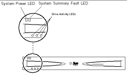
 FIGURE 5-1 Front Panel LEDs With Bezel

Graphic shows the array's front with LEDs for System Power, System Summary Fault, and Drive Activity LEDs.[ D ]

 FIGURE 5-2 Front Panel LEDs With Bezel Removed

Graphic of the array front with bezel removed, with Drive Activity LEDs and Binary SCSI LEDs. [ D ]
TABLE 5-1 Front Panel LEDs

LED

Color

Indication

Action

System Power

Green

The array is powered on.

No action is necessary.


Unlit

The array is powered off.

No action is necessary.

System Summary Fault

Unlit

The array is performing normally.

No action is necessary.

System Summary Fault

Amber

There are two possible causes:

  • The power is in standby mode

Or:

  • A component other than a drive has failed, such as the power supply or a fan. The System Summary Fault LED does not indicate if a drive has failed. The Drive Activity LEDs provide some diagnostic information on the disk drives.

Follow these steps:

  1. Check to see if the power is in Standby mode. If so, turn on the power. See Power Supply.
  2. If the power is on, it is a component failure. You must replace the entire array. Remove all disk drives before returning the array. See Removing and Replacing a Disk Drive. Contact your local Sun service representative for more details.

Disk Drive

Solid green

A drive is present in that slot but is not active.

No action is necessary.


Flashing green

A drive is present in that slot and is active.

No action is necessary.


Unlit

No drive is present in that slot, or the disk drive has failed.

If the power is on, a drive is present in that slot, and the drive LED is unlit, then you must replace the drive. See Removing and Replacing a Disk Drive.

Binary SCSI LEDs

Solid green (in various combinations)

The position of the binary display indicates the base number (first number) of the three drive sequence. See the pull-out card or To Check the Binary SCSI ID LED Display.

No action is necessary.


Note - If a disk drive is under an unusually heavy load (for example, if the drive is being reformatted), the Disk Drive LED might be unlit for a long period of time, even though the drive has not failed. You should see a message in your console window telling you that the disk drive is offline if the disk drive has truly failed.


procedure icon  To Check the Binary SCSI ID LED Display

Check the Binary SCSI LED display to confirm that the SCSI IDs are set correctly or to determine which SCSI IDs are assigned to which disk drives.

1. Remove the front bezel by pressing the latches on both ends and pulling the bezel away from the array.

See To Remove the Bezel, if needed.
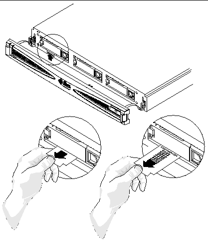
 FIGURE 5-3 Checking the Binary SCSI LEDs

Graphic shows the bezel removed from the array's front. Three zooms show finding and removing the binary SCSI LED card from below the left drive slot.

2. Locate the Binary SCSI LEDs (FIGURE 5-3).

3. Use TABLE 5-2 or the pullout card attached to the system to determine which SCSI IDs are assigned to the drives in the array.

The disk drive SCSI ID numbers are assigned in sequences of three numbers in a row. Each customer chooses the numbers. The first number in the sequence is the base address. The installer sets the base address using the SCSI toggle switch on the back of the array. See Setting the SCSI IDs for the Drives for more information on how to set the SCSI IDs.

The base address is represented in binary format on the top row of disk drive LEDs on the front of the array.


Note - Rows 5-9 in the table represent SCSI ID sequences that cannot be used because SCSI ID 7 is assigned to the SCSI controller (unless the default is changed).


TABLE 5-2 Binary SCSI ID LEDs

Base SCSI Target ID

Back Hexadecimal SCSI ID Switch

Front Binary LED Display

SCSI Target IDs of Disk Drive Bays

0

0

left to right: four white LEDs 

0, 1, 2

1

1

left to right: three white LEDs and one black LED 

1, 2, 3

2

2

left to right: two white LEDs, one black LED, and one white LED 

2, 3, 4

3

3

left to right: two white LEDs, and two black LEDs 

3, 4, 5

4

4

left to right: one white LED, one black LED and two white LEDs 

4, 5, 6

5

5

left to right: one white LED, one black LED, one white LED, and one black LED 

5, 6, 7

6

6

left to right: one white LED, two black LEDs, and one white LED 

6, 7, 8

7

7

left to right: one white LED, and three black LEDs 

7, 8, 9

8

8

left to right: one white LED, and three black LEDs 

8, 9, A

9

9

left to right: one black LED, two white LEDs, and one black LED 

9, A, B

10

A

left to right: one black LED, one white LED, one black LED, and one white LED 

A, B, C

11

B

left to right: one black LED, one white LED, and two black LEDs  

B, C, D

12

C

left to right: two black LEDs, and two white LEDs  

C, D, E

13

D

left to right: two black LEDs, one white LED, and one black LED 

D, E, F

14

E

left to right: three black LEDs, and one white LED 

E, F, 0

15

F

left to right: four black LEDs 

F, 0, 1


Note - Some servers reserve SCSI ID 6 for use by CD drives and IDs 0 and 1 for internal drives. See To Determine the Drive Bay's SCSI ID Sequence and Base ID for more information.


4. Replace the front bezel.

Checking Back Panel LEDs

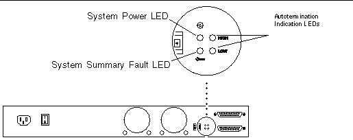
 FIGURE 5-4 Back Panel LEDs

Graphic shows the array's right back. A zoom shows the System Power LED, System Summary Fault LED, Autotermination Indication LEDs, HIGH and LOW.

System Power and System Summary Fault LEDs

The System Power and System Summary Fault LEDs give the same diagnostic information as the System Power and System Summary Fault LEDs at the front of the array. Refer to TABLE 5-1 for more information.

Checking Autotermination Indication LEDs

The Autotermination Indication LEDs indicate if the array is part of an UltraSCSI, wide SCSI, or narrow SCSI daisy chain. They also indicate the array's position in the daisy chain.

TABLE 5-3 Autotermination Indication LEDs

HIGH

LOW

Meaning

Off

Off

The array is the first device in the UltraSCSI or wide SCSI daisy chain; another device follows the Sun StorEdge S1 array.

On

On

The array is the last or only device in the UltraSCSI or wide SCSI daisy chain.

On

Off

A narrow SCSI device follows the array in the daisy chain.

Off

On

N/A


Note - UltraSCSI devices (such as the Sun StorEdge S1 array) at the end of a daisy chain do not require a terminator, but some wide SCSI devices at the end of a daisy chain do require a terminator. Refer to the documentation that came with your wide SCSI device to determine if it needs a terminator. Narrow SCSI devices at the end of a daisy chain always require a terminator.


FIGURE 5-5 shows two arrays connected in a daisy chain to a host system. Both HIGH and LOW autotermination LEDs are Off on the top array, which indicates that the array is the first device on the daisy chain and that another device follows it. On the next array, both HIGH and LOW autotermination LEDs are On, which indicates that the array is the last array in the daisy chain.
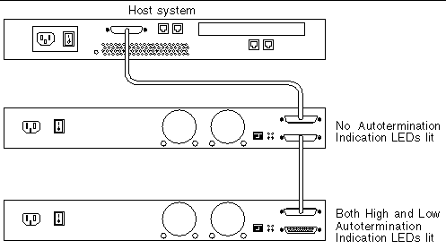
 FIGURE 5-5 Autotermination Indication LEDs in an UltraSCSI or Wide SCSI Daisy Chain

Graphic shows two arrays connected to a host system. Autotermination LEDs indicate the first array and the last array in the daisy chain.

FIGURE 5-6 shows an array and a narrow SCSI device daisy-chained to a server. The HIGH Autotermination LED is On and LOW is Off on the array, which indicates that a narrow SCSI device follows the array in the daisy chain.
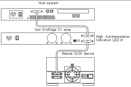
 FIGURE 5-6 Autotermination Indication LEDs in a Narrow SCSI Daisy Chain

Graphic shows an array and a narrow SCSI device connected to a server. The array's Autotermination LED indicates that a narrow SCSI device follows.[ D ]


Cleaning the Sun StorEdge S1 Array Screens

To ensure optimum performance from your array, clean the screens at the front and back of the array periodically.


procedure icon  To Clean the Front Bezel Screen

1. Remove the front bezel.

See Removing the Front Bezel if needed.

2. Pull one of the tethers towards you until the head of the tether stops it from coming out of the hole in the chassis (FIGURE 5-7).
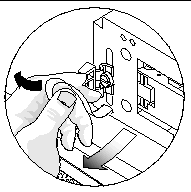
 FIGURE 5-7 Pulling a Tether Until It Stops

Graphic shows a hand pulling the left tether away from the array.

3. Push the tether to one side so that its head comes partially out of the hole in the chassis (FIGURE 5-8).
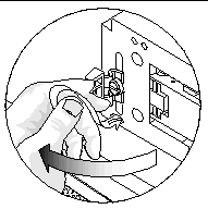
 FIGURE 5-8 Pushing the Tether to One Side Until it Head Emerges

Graphic shows a hand pushing the left tether to the left so the tether's head comes partially out of its hole.

4. Push the same tether in the opposite direction (FIGURE 5-9).
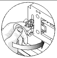
 FIGURE 5-9 Pushing the Tether in the Opposite Direction

Graphic shows a hand pushing the left tether to the right.

5. Pull the head of the tether entirely out of the chassis (FIGURE 5-10).
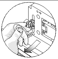
 FIGURE 5-10 Pulling the Head of the Tether out of the Array

Graphic shows a hand pulling the head of the left tether out of the array.

6. Repeat Step 2 through Step 5 for the tether at the other end of the bezel.

7. Use a vacuum cleaner to clean the dust from the screen at the back of the bezel.
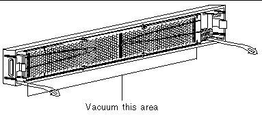
 FIGURE 5-11 Cleaning the Front Bezel Screen

Graphic shows a callout "Vacuum this area" pointing to the screen.

procedure icon  To Reattach the Bezel's Tethers to the Array

1. Position one of the tethers in front of its hole in the chassis and angle it so that half of its head enters the hole in the chassis.

You might need to push the tether's head in gently.

2. With one half of the tether's head inside the hole in the chassis, change the angle so that you can gently push the head of the tether completely into its hole.

You might need to push the tether's head in gently.

3. Repeat Step 1 and Step 2 for the tether at the other end of the bezel.


procedure icon  To Clean the Back Fan Screens

single-step bulletGo to the back of the array and use a vacuum cleaner to clean all the dust and debris from the fan screens.

 FIGURE 5-12 Cleaning the Back Fan Screens

Graphic shows the back of the array. The callout "Vacuum these areas" indicates the fan screens., which are a little to the right of center.


Removing and Replacing an Array

These instructions are for removing a Sun StorEdge S1 array or another type of array and replacing it with a Sun StorEdge S1 array. If replacing any other array than the Sun StorEdge S1 array, refer to that array's documentation for additional information about how to remove that array.


Note - If your host system supports hot-swap attaching and detaching of external SCSI devices, do not power off your system. For example, if your host system is a Netra ct 400 or 800 or similar server, you should not power off the system. Start the removal of the server at Step 3.


1. Make note of the SCSI ID addresses assigned to the drives in the array that you are going to remove.

2. Power off the host system, if necessary.

3. Power off the array.

See To Power Off the Array.

4. Disconnect the SCSI and power cables for the array that you are going to remove.

5. Remove the drives from the array.

See Removing and Replacing a Disk Drive.

6. Remove the array from the rack.

7. Install the new Sun StorEdge S1 array.

See Chapter 3.