| Exit Print View | |
Sun Datacenter InfiniBand Switch 72 Topic Set |

|
Documentation, Support, and Training
Understanding Switch Specifications
Network Management Connector and Pins
USB Management Connector and Pins
Understanding InfiniBand Cabling
Floor and Underfloor Delivery of InfiniBand Cables
Overhead Delivery of InfiniBand Cables
Understanding the Installation
Accessing the Management Controller
Access the Management Controller From the Network Management Port
Access the Management Controller From the USB Management Port
Verifying the InfiniBand Fabric
Discover the InfiniBand Fabric Topology
Perform Diagnostics on the InfiniBand Fabric
 | Caution - The airflow through the switch is in from the fans, through the chassis, and out at the connector panel. The front of the switch chassis (fan end) intakes from the cold aisle and the rear of the switch chassis (connector end) exhausts to the hot aisle. This flow direction requires you to install the switch in an orientation that is the opposite of what you might assume. |
Identify the prerequisite and subsequent installation tasks that you must perform in conjunction with this procedure.
If installed, open the rack doors.
Assemble the cable management extenders.
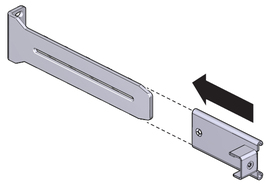
Slide the attachment bracket over the extender, so that the tab on the bracket is opposite the flange on the extender.
The open end of the tab is toward the flange. The flat end of the tab is toward the rear of the extender.
Place the attachment plate on the flange side of the extender, opposite the attachment bracket.
Use two screws to sandwich the attachment bracket and plate to the extender, in the position farthest from the flange.
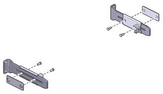
Using a No. 2 Phillips screwdriver, tighten the two screws.
Repeat from ![]() Step a for the other cable management extender.
Step a for the other cable management extender.
Attach the cable management extenders and long rails to the rear of the rack.
Place the long rail to the mounting location on the rear rack post.
Butt the flange of the extender to the flange of the long rail.
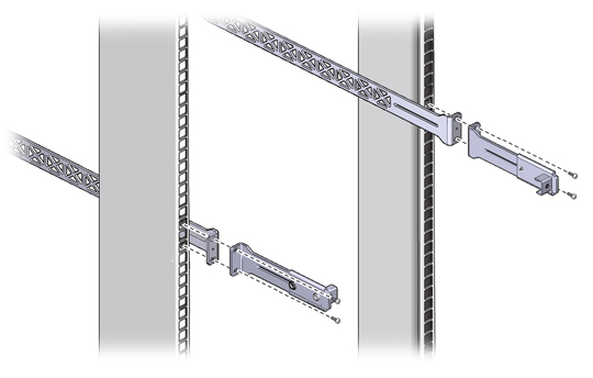
Secure the assembly to the post with two captive nuts and two screws.
Repeat from ![]() Step a for the other cable management extender and long rail.
Step a for the other cable management extender and long rail.
Attach the long front brackets (with cutouts) to the switch with 4 screws on each side.
The flange of the long front brackets point away from the switch.
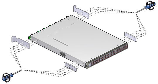
Attach the C-shaped brackets to the switch with 4 screws on each side.
The edge of the C-shaped bracket is flush to the rear of the chassis.
Route the power cords through the rack with the female end at the front of the rack where the switch will install.
Ensure that there is 24 inches (610 mm) of power cord slack at the front of the rack to provide an adequate service loop for when removing the switch from the rack.
Carefully lift the switch and slide it into the rack, from the front rearward.
Ensure that the ends of the long rails slide into the C-shaped brackets at the rear of the switch chassis and that the power cords lay into the cut-outs of the long front mounting brackets.
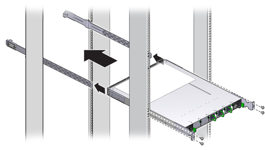
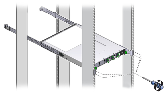
Mount the front of the switch chassis to the front rack posts with two captive nuts and two screws at each side.
Tighten the screws securely.
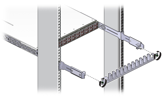
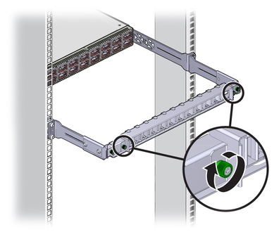
Install the cable management bracket to the tabs of the attachment brackets at the rear of the switch, tightening the thumbscrews on each side of the cable management bracket.
Install the cable management bracket cover.
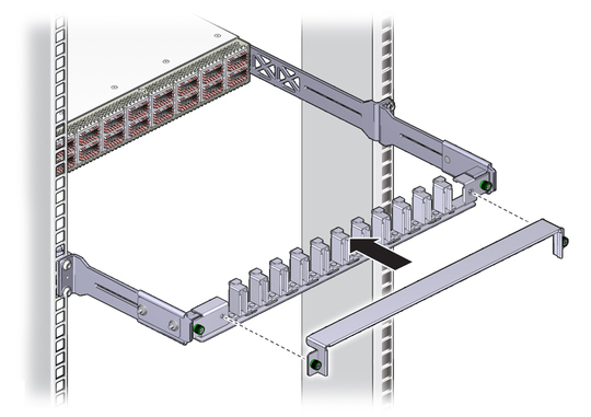
Tighten the thumbscrews on each side of the cover.
Attach the management cables.