| Exit Print View | |
Sun Netra CP3270 ATCA Blade Server User’s Guide |

|
Documentation, Support, and Training
Evaluating Product Compatibility
Preparing to Install the Blade Server
Installing Components and Blade Server
Installing Optional Components
Install an Advanced Mezzanine Card
Software and Firmware Upgrades
Software and Firmware Upgrades
Administering Parameters and Configurations
Administering User Accounts and Security
A compatible ARTM must be used with the blade server for rear I/O access. The ARTM enables access to the network, a boot device, and a console terminal. You can use one of the Sun Netra CP32x0 ARTMs, or you can design your own compatible ARTM.
Note - The following procedure provides a general set of instructions for installing an ARTM on the blade server. Refer to the ARTM documentation for specific instructions on installing and configuring these components.
Take antistatic precautions.
See ![]() Safety Requirements.
Safety Requirements.
From the rear of the system, choose the corresponding slot for the ARTM.
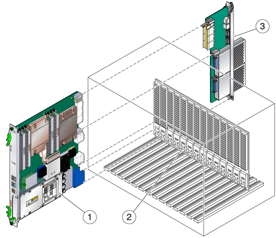
The ARTM must be installed, inline, behind a compatible blade server.
For example, if the blade server will be installed in slot 3, the
corresponding ARTM must be installed at the back of the system in slot
3 (see ![]() Installing an ARTM). If you do not install the ARTM and the blade
server in corresponding slots, the system will recognize the blade server and not
the ARTM.
Installing an ARTM). If you do not install the ARTM and the blade
server in corresponding slots, the system will recognize the blade server and not
the ARTM.

Figure Legend
1 Blade server (installed from the front)
2 ATCA backplane
3 Netra CP32x0 ARTM (installed from rear in corresponding slot to blade server’s front slot)
Remove the slot filler panel from the selected slot, if necessary.
Retrieve the ARTM from the ship kit.
Configure the ARTM connectors for the blade server.
See ![]() Configuring Ports and Pins.
Configuring Ports and Pins.
If you are using one of the Sun Netra ARTMs, refer to the documentation for detailed information.
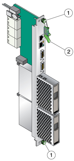
Prepare the ARTM by opening the injector/ejector latch at the top of the module.

Figure Legend
1 Locking screws
2 Injector/ejector latch
Carefully align the edges of the ARTM with the card guides in the appropriate slot.
Look into the enclosure to verify correct alignment of the rails in the guides.
Keep the ARTM aligned in the guides, and slide the module in until the injector/ejector latches engage the card cage.
Push the ARTM into the backplane connectors, and close the latch.
Tighten the locking screws to ensure that the module is secured into the ATCA shelf.
Install the blade server into the front of the ATCA shelf in the corresponding slot.