| Skip Navigation Links | |
| Exit Print View | |

|
Sun Server X2-4 (formerly Sun Fire X4470 M2) Installation Guide |
| Skip Navigation Links | |
| Exit Print View | |

|
Sun Server X2-4 (formerly Sun Fire X4470 M2) Installation Guide |
1. Preparing to Install the Server
Server Installation Task Checklist
Sun Server X2-4 Supported Components and Capabilities
2. Installing the Server Into a Rack With Slide-Rails
Server Installation Process Overview
Installing the Mounting Brackets Onto the Server
Attaching the Slide-Rail Assemblies to the Rack
Installing the Server Into the Slide-Rail Assemblies
Install Server Into the Slide-Rail Assemblies
Installing the Cable Management Arm
Verifying Operation of the Slide-Rails and CMA
Verify Operation of Slide-Rails and CMA
3. Attaching Cables and Power Cords
Back Panel Connectors and Ports
Attaching Cables to the Server
4. Connecting to Oracle ILOM and Applying Main Power to the Server
Log In to Oracle ILOM Using a Local Serial Connection
Log In to Oracle ILOM Using a Remote Ethernet Connection
Modify Network Settings From the Oracle ILOM CLI
Modify Network Settings From the Oracle ILOM Web Interface
Test IPv4 or IPv6 Network Configuration From the Oracle ILOM CLI
Test IPv4 or IPv6 Network Configuration From the Oracle ILOM Web Interface
Applying Main Power to the Server
Apply Main Power to the Server
5. Configuring the Preinstalled Oracle Solaris OS or the Oracle VM Software
Preparing for the Oracle Solaris Configuration
Preinstalled Oracle Solaris Operating System RAID Limitations
Oracle Solaris 10 and 11 Configuration Worksheet
Configuring the Preinstalled Oracle Solaris 11 Operating System
Configure the Preinstalled Oracle Solaris 11 Operating System
Oracle Solaris 11 Operating System Documentation
Configuring the Preinstalled Oracle Solaris 10 Operating System
Configure the Preinstalled Oracle Solaris 10 Operating System
Oracle Solaris 10 Operating System Documentation
Reinstalling the Oracle Solaris 10 or 11 Operating System
Download the Oracle Solaris Operating System
Preparing for the Oracle VM Configuration
Preinstalled Oracle VM Server Compatiblitiy Requirements
Oracle VM Configuration Worksheet
Configuring the Preinstalled Oracle VM 3.0 Software
Configure the Preinstalled Oracle VM Server
6. Installing an Operating System
Installing an Operating System
7. Getting Server Firmware and Software
Firmware and Software Access Options
Available Software Release Packages
Accessing Firmware and Software
Download Firmware and Software Using My Oracle Support
Use this procedure to connect power cords to the server. When the power cords are connected, the server will be in standby power mode.
Note - By default, only a two-CPU system will operate from low-line (100 to 127 Volt) AC sources. The system requires high-line (200 to 240 Volt) AC sources to turn on main power of a four-CPU system.
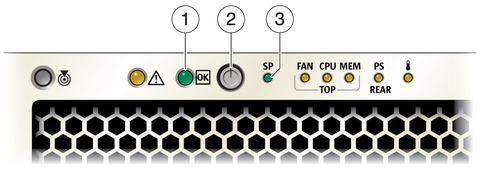
When power is connected, the server boots into standby power mode. The SP OK/Fault LED flashes while Oracle ILOM is starting, and the main Power/OK LED remains off until Oracle ILOM is ready for system log in (Front Panel Indicators and Power Button). After a few minutes, the main Power/OK LED slowly flashes the standby pattern, indicating the service processor (SP) is ready for use. Note that the server is not initialized or powered on yet.
Figure 3-2 Front Panel Indicators and Power Button

Figure Legend
1 Main Power/OK LED
2 Power Button
3 SP OK/Fault LED