Setting Up an EVS Virtual Tenant Network
A virtual switch is either a software or hardware entity that facilitates inter-virtual machine (VM) communication by looping the inter-VM traffic within a physical machine rather than sending it out on the wire.
EVS enables you to explicitly create virtual switches that span one or more nodes (physical machines), which further virtualizes your network. The virtual switch that you create represents an isolated L2 segment that uses either VLANs or VXLANs to implement the isolation.
For more information about the EVS architecture, see EVS Components in Managing Network Virtualization and Network Resources in Oracle Solaris 11.2 .
This scenario's overall objective is to set up and deploy an EVS virtual tenant network. The primary objective is to create an elastic virtual switch (vswitch) that connects two compute nodes so that both nodes are part of the same L2 segment and can communicate with each other.
-
Deploy a virtual tenant network with two zones that are connected to the network through anet VNICs.
-
Deploy the VNICs on a private cloud infrastructure that has two compute nodes.
-
Use a VLAN L2 infrastructure to instantiate the private virtual tenant network.
The individual objectives for this scenario are as follows:
Note - Other L2 technologies such as VXLANs are also supported. For more information, see Use Case: Configuring an Elastic Virtual Switch for a Tenant in Managing Network Virtualization and Network Resources in Oracle Solaris 11.2 .
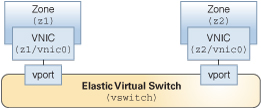
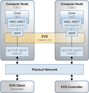
The following figures represent the virtual and physical components of the elastic virtual switch configuration that is used in this scenario.
Figure 2-1 Virtual Components of an EVS Switch Configuration

Figure 2-2 Physical Components of an EVS Switch Configuration

-
Two compute nodes (CN1 and CN2).
-
Two zones (z1 and z2) that are configured on CN1 and CN2, respectively.
-
The two zones (z1 and z2) are configured with a VNIC anet resource on each zone.
-
One node that acts as the EVS controller.
-
One node that acts as the EVS client.
Note - The EVS controller and the EVS client can be located on the same host. -
Two uplink-ports (net2) that specify the datalink to be used for the VLANs.
The following setup uses four network nodes with the following configuration: