Objectives for Creating and Deploying a Cloud Environment
-
Configure a virtual network on an Oracle VM Server for SPARC service domain.
-
Configure two Oracle VM Server for SPARC guest domains to be used as containers for multiple zones that are configured within each guest.
-
Have each guest domain then correspond to a specific compute node within the cloud that will run the various workloads.
-
Configure the elastic virtual switches that will be used to connect the zones running in the guest domains.
-
Carve up the guest domains into multiple zones that will run the various workloads.
The deployment objectives for this scenario are as follows:
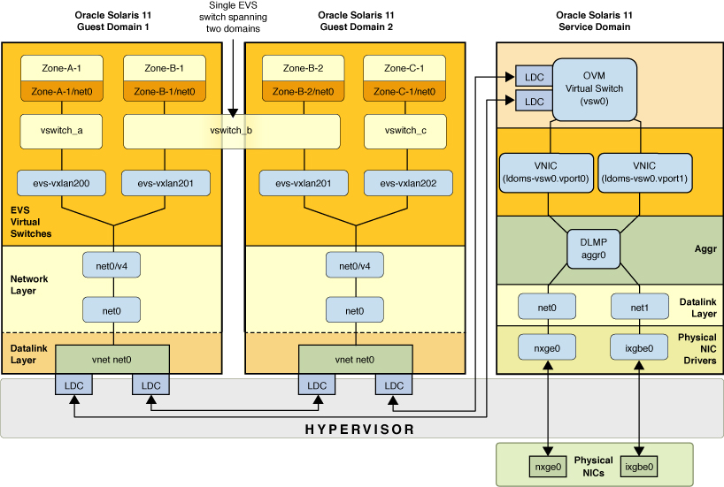
The following figure illustrates the two distinct levels of network virtualization that you create with this configuration.
Figure 2-3 Combining Network Virtualization Features With Oracle VM Server for SPARC

On the first level, you configure network virtualization features that are supported by Oracle VM Server for SPARC. This part of the network virtualization combines Oracle VM Server for SPARC configuration with the Oracle Solaris 11 OS that is running on the service domain. The vnet configuration takes place at this first level of virtualization. Because the configuration only relies upon IP connectivity from the guest domains, no additional support from Oracle VM Server for SPARC is required for the configuration on the second network virtualization level to work.
On the second level, EVS is used to create elastic virtual switches across the guest domains. EVS is configured to use the vnet interfaces as uplinks. VXLAN datalinks are automatically created by EVS from each guest domain and then used to encapsulate the traffic of the individual elastic virtual switches.
-
Two physical NICs, nxge0 and ixgbe0, which are directly assigned to the service domain where they are represented by datalinks net0 and net1.
-
To provide high availability in case of failure of the physical NICs, net0 and net1 in the service domain are grouped into the DLMP aggregation (aggr0).
-
The aggregation, aggr0, is then connected to an Oracle VM Server for SPARC virtual switch in the service domain named vsw0.
Two VNICs, ldoms-vsw.vport0 and ldoms-vsw.vport1, are automatically created by vsw0, with each VNIC then corresponding to the Oracle VM for SPARC vnet instances within the guest domains.
-
The vsw0 and the vnet instances communicate with each other through the hypervisor by using Logical Domain Channels (LDCs).
-
Each guest uses its instance of the vnet0 driver, which appears in the guest domain as a datalink (net0) for the purpose of communicating with other guest domains and the physical network.
-
In each guest domain, the vnet datalinks (net0) are configured with the IP interface net0/v4.
-
Each guest domain is an EVS compute node, with three EVS switches, vswitch_a, vswitch_b, and vswitch_c, that are configured from the EVS controller (not shown in this figure).
-
EVS is configured to use a VXLAN as its underlying protocol. For each guest domain that uses an elastic virtual switch, EVS automatically configures a VXLAN datalink. These VXLAN datalinks are named evs-vxlanid, where id is the VXLAN ID that is assigned to the virtual switch.
-
In the guest domains, Oracle Solaris zones are configured to run the tenants' workload. Each zone is connected through a VNIC and a virtual port (not shown in this figure) to one of the EVS switches.
-
Zone-B1 and Zone-B2 belong to the same user and are running on two different guest domains. The EVS switch, vswitch_b, is instantiated on both guest domains. To the two zones, it appears as if each zone is connected to a single Ethernet segment that is represented by vswitch_b and isolated from the other virtual switches.
-
EVS automatically creates the VXLAN datalinks that are needed by the various elastic virtual switches. For example, for vswitch_b, EVS automatically created a VXLAN datalink named evs-vxlan201 on each of the guest domains.
The figure represents the following configuration: