Simple Bridged Network
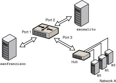
The following figure shows a simple bridged network configuration.
Figure 4-1 Simple Bridged Network

The bridge, goldengate, is an Oracle Solaris system that has bridging configured. The systems sanfrancisco and sausalito are physically connected to the bridge. Network A uses a hub that is physically connected to the bridge on one side and to three computer systems on the other side. The bridge ports are the links net0, net1, and net2.
How Oracle Solaris Bridges Are Implemented in the Network Stack
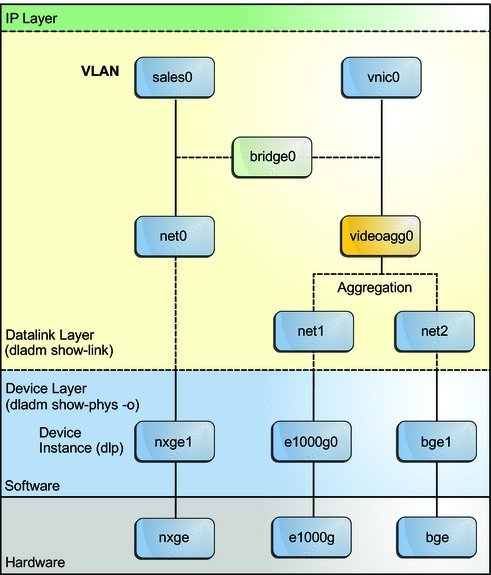
In Oracle Solaris, you can configure bridges on the datalink layer of the same network stack implementation, as shown in the following figure.
Figure 4-2 Bridges in the Network Stack for Oracle Solaris

Two interfaces, net0 and videoagg0, are configured as a bridge, bridge0. Packets that are received on one interface are forwarded to the other interface. After the bridge configuration, both interfaces can still be used to configure VLANs and IP interfaces.