Physical I/O Architecture
The physical I/O architecture for the SPARC M8 and SPARC M7 servers has changed from previous releases of the M series servers. Different names are used, and the CPU no longer owns the PCIe fabric.
I/O Terminology
The terms that are used to describe the I/O architecture of SPARC M8 and SPARC M7 servers include:
-
Root complex
– In a PCIe device path, the root complex is the first element (for example, /pci@300). In previous releases of the M series servers, the CMT processors contained one or more root complexes. In SPARC M7 and SPARC M8 servers, the root complex has moved to the I/O hub controller chip (IOH). Each server has one or more IOH controller chips.
-
Root port
– A root complex can have one or more root ports. Each root port is independent from any other in that fabric. However, any device under the same root complex shares that fabric.
The root port is the second term in a PCIe device path. The first root port is
pci@1, the second is
pci@2, and so on.
-
PCI Bus
– This is the label that you use to assign a root complex to a logical domain.
Root Complex Assignments (SPARC M8-8)
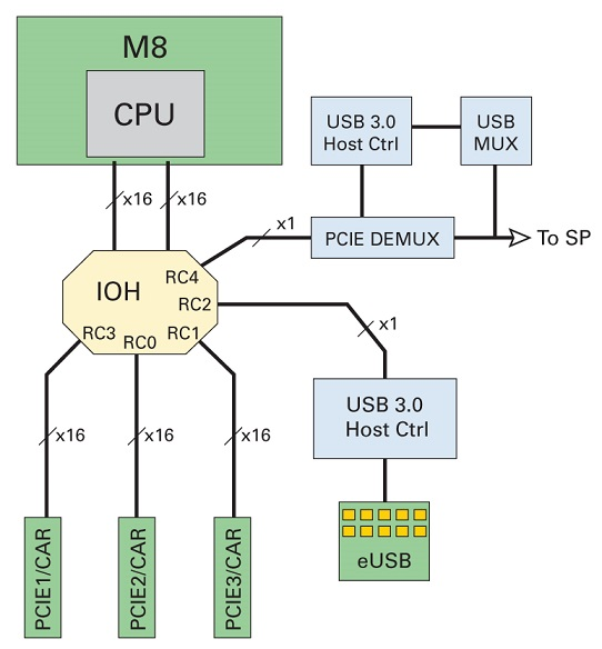
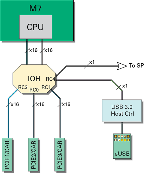
The root complex assignments are slightly different in the SPARC M8-8 server compared to the SPARC M7 servers. SPARC M8-8 uses two root complexes (RC2, RC4) to connect to the eUSB device and the SP while SPARC M7 systems use a single root complex (RC4) for connecting the eUSB device and the SP. This allows assignment of an eUSB device on all CMIOUs to guest domains where they can be used to perform iSCSI boot using IPoIB. In contrast, on M7 systems, this can only be done on CMIOUs that are not providing any rKVMS services.
The following figure shows the root complex assignments for one SPARC M8-8 CMIOU.
Figure 1 SPARC M8-8 CMIOU Root Complex

For SPARC M8 and SPARC M7, each root complex has a device path, a service path, and a bus name. The following table shows the naming for CMIOU0 and CMIOU1 as an examples. For all of the CMIOU naming examples, see I/O Component Relationships.
Table 1 I/O Paths for SPARC M8 and SPARC M7 CMIOUs
|
|
|
|
|
|
CMIOU0
|
/pci@301/pci@1
|
/SYS/CMIOU0/PCIE3
|
pci_1
|
Typically used for boot disk adapter.
|
|
|
/pci@300/pci@1
|
/SYS/CMIOU0/PCIE2
|
pci_0
|
|
|
|
/pci@303/pci@1
|
/SYS/CMIOU0/PCIE1
|
pci_3
|
|
|
CMIOU1
|
/pci@306/pci@1
|
/SYS/CMIOU1/PCIE3
|
pci_6
|
Typically used for network adapter.
|
|
|
/pci@305/pci@1
|
/SYS/CMIOU1/PCIE2
|
pci_5
|
|
|
|
/pci@308/pci@1
|
/SYS/CMIOU1/PCIE1
|
pci_8
|
|
|
Root Complex Assignments (SPARC M7)
The following figure shows the root complex assignments for one SPARC M7 series server CMIOU.
Figure 2 SPARC M7 CMIOU Root Complex

Each root complex has a device path, a service path, and a bus name as shown in the examples in Figure 1, Table 1, I/O Paths for SPARC M8 and SPARC M7 CMIOUs. For all of the CMIOU naming examples, see I/O Component Relationships.
I/O Architecture Layout (SPARC M8-8)
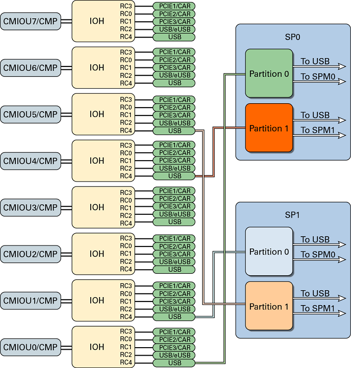
I/O Architecture Layout for SPARC M8-8 with One PDomain
shows the I/O architecture layout for the SPARC M8-8 server with one PDomain. For the SPARC M8-8 server with two PDomains, the diagram represents the I/O architecture layout for both static domains.
The diagram shows connections between the SPs and CMIOU4 and CMIOU5. While the wires are present, the connections are not active in the SPARC M8-8 server with one PDomain. They are active in the SPARC M8-8 server with two PDomains.
Figure 3 I/O Architecture Layout for SPARC M8-8 with One PDomain

I/O Architecture Layout (SPARC M7)
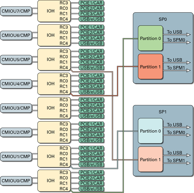
I/O Architecture Layout for SPARC M7 with One PDomain shows the I/O architecture layout for the SPARC M7-8 server with one PDomain. For the SPARC M7-8 server with two PDomains, the diagram represents the I/O architecture layout for both static domains. For the SPARC M7-16 server, the diagram represents one half of the I/O architecture.
Note -
The diagram shows connections between the SPs and CMIOU4 and CMIOU5. While the wires are physically present, the connections are not active in the SPARC M7-8 server with one PDomain. They are active in the SPARC M7-8 server with two PDomains and the SPARC M7-16 servers.
Figure 4 I/O Architecture Layout for SPARC M7 with One PDomain

I/O Component Example Output
The ldm list-io command lists information about the I/O devices on the server.
The following example shows output for a M7-8 server, and the M8-8 server output is similar. This output has been edited for clarity.
# ldm list-io -l

NAME                                       TYPE   BUS      DOMAIN    STATUS
----                                       ----   ---      ------    ------
...
/SYS/CMIOU0/PCIE2                          PCIE   pci_0    primary   EMP
[pci@300/pci@1]
/SYS/CMIOU0/PCIE3                          PCIE   pci_1    primary   OCC
[pci@301/pci@1]
    LSI,sas@0/iport@80
    LSI,sas@0/iport@v0
/SYS/CMIOU0/PCIE1                          PCIE   pci_3    primary   OCC
[pci@303/pci@1]
    network@0
    network@0,1
    network@0,2
    network@0,3
...
In the output you can find the following about installed PCIe devices:
- Root complex and root port
-
Shown in brackets. For the device /SYS/CMIOU0/PCIE2 the [pci@300/pci@1] shows that the root complex is pci@300 and the root port is pci@1.
- Slot number
-
Shown in the Oracle ILOM service path. For the device /SYS/CMIOU0/PCIE2, the PCIE2 indicates the device is located in slot 2 on CMIOU0)
- Bus name
-
Shown in the BUS column. For the device /SYS/CMIOU0/PCIE2, the Bus is pci_0. You use the Bus label to assign a root complex to a logical domain.
I/O Component Relationships
This table explains the DCU and CMIOU component relationships in the servers.
Table 2 Server I/O Components
|
|
|
|
SPARC M8-8 or SPARC M7-8 (two PDomains)
|
Two static with four CMIOUs each
|
CMIOU0–3
CMIOU4–7
|
|
SPARC M8-8 or SPARC M7-8 (one PDomain)
|
One static with eight CMIOUs
|
CMIOU0–7
|
|
SPARC M7-16
|
Four dynamic with four CMIOUs each
|
CMIOU0–3
CMIOU4–7
CMIOU8–11
CMIOU12–15
|
|
The following additional tables list the relationships between the root complex numbers, PCIe slot numbers, root complex names, and bus names on each CMIOU that you can install in the servers.
For CMIOU0 through CMIOU3 on all servers:
For CMIOU4 through CMIOU7 on all servers:
For CMIOU8 through CMIOU15 on M7-16 Servers:
Table 3 I/O Component Naming for CMIOU0
|
|
|
|
|
0
|
PCIE2
|
pci@300
|
pci_0
|
|
1
|
PCIE3
|
pci@301
|
pci_1
|
|
2 (M8 only)
|
N/A
|
pci@302
|
pci_2
|
|
3
|
PCIE1
|
pci@303
|
pci_3
|
|
4
|
N/A
|
pci@304
|
pci_4
|
|
Table 4 I/O Component Naming for CMIOU1
|
|
|
|
|
0
|
PCIe2
|
pci@305
|
pci_5
|
|
1
|
PCIE3
|
pci@306
|
pci_6
|
|
2 (M8 only)
|
N/A
|
pci@307
|
pci_7
|
|
3
|
PCIE1
|
pci@308
|
pci_8
|
|
4
|
N/A
|
pci@309
|
pci_9
|
|
Table 5 I/O Component Naming for CMIOU2
|
|
|
|
|
0
|
PCIE2
|
pci@30a
|
pci_10
|
|
1
|
PCIE3
|
pci@30b
|
pci_11
|
|
2 (M8 only)
|
N/A
|
pci@30c
|
pci_12
|
|
3
|
PCIE1
|
pci@30d
|
pci_13
|
|
4
|
N/A
|
pci@30e
|
pci_14
|
|
Table 6 I/O Component Naming for CMIOU3
|
|
|
|
|
0
|
PCIE2
|
pci@30f
|
pci_15
|
|
1
|
PCIE3
|
pci@310
|
pci_16
|
|
2 (M8 only)
|
N/A
|
pci@311
|
pci_17
|
|
3
|
PCIE1
|
pci@312
|
pci_18
|
|
4
|
N/A
|
pci@313
|
pci_19
|
|
Table 7 I/O Component Naming for CMIOU4
|
|
|
|
|
0
|
PCIE2
|
pci@314
|
pci_20
|
|
1
|
PCIE3
|
pci@315
|
pci_21
|
|
2 (M8 only)
|
N/A
|
pci@316
|
pci_22
|
|
3
|
PCIE1
|
pci@317
|
pci_23
|
|
4
|
N/A
|
pci@318
|
pci_24
|
|
Table 8 I/O Component Naming for CMIOU5
|
|
|
|
|
0
|
PCIE2
|
pci@319
|
pci_25
|
|
1
|
PCIE3
|
pci@31a
|
pci_26
|
|
2 (M8 only)
|
N/A
|
pci@31b
|
pci_27
|
|
3
|
PCIE1
|
pci@31c
|
pci_28
|
|
4
|
N/A
|
pci@31d
|
pci_29
|
|
Table 9 I/O Component Naming for CMIOU6
|
|
|
|
|
0
|
PCIE2
|
pci@31e
|
pci_30
|
|
1
|
PCIE3
|
pci@31f
|
pci_31
|
|
2 (M8 only)
|
N/A
|
pci@31g
|
pci_32
|
|
3
|
PCIE1
|
pci@321
|
pci_33
|
|
4
|
N/A
|
pci@322
|
pci_34
|
|
Table 10 I/O Component Naming for CMIOU7
|
|
|
|
|
0
|
PCIE2
|
pci@323
|
pci_35
|
|
1
|
PCIE3
|
pci@324
|
pci_36
|
|
2 (M8 only)
|
N/A
|
pci@325
|
pci_35
|
|
3
|
PCIE1
|
pci@326
|
pci_38
|
|
4
|
N/A
|
pci@327
|
pci_39
|
|
Table 11 I/O Component Naming for CMIOU8
|
|
|
|
|
0
|
PCIE2
|
pci@328
|
pci_40
|
|
1
|
PCIE3
|
pci@329
|
pci_41
|
|
3
|
PCIE1
|
pci@32b
|
pci_43
|
|
4
|
N/A
|
pci@32c
|
pci_44
|
|
Table 12 I/O Component Naming for CMIOU9
|
|
|
|
|
0
|
PCIE2
|
pci@32d
|
pci_45
|
|
1
|
PCIE3
|
pci@32e
|
pci_46
|
|
3
|
PCIE1
|
pci@330
|
pci_48
|
|
4
|
N/A
|
pci@331
|
pci_49
|
|
Table 13 I/O Component Naming for CMIOU10
|
|
|
|
|
0
|
PCIE2
|
pci@332
|
pci_50
|
|
1
|
PCIE3
|
pci@333
|
pci_51
|
|
3
|
PCIE1
|
pci@335
|
pci_53
|
|
4
|
N/A
|
pci@336
|
pci_54
|
|
Table 14 I/O Component Naming for CMIOU11
|
|
|
|
|
0
|
PCIE2
|
pci@337
|
pci_55
|
|
1
|
PCIE3
|
pci@338
|
pci_56
|
|
3
|
PCIE1
|
pci@33a
|
pci_58
|
|
4
|
N/A
|
pci@33b
|
pci_59
|
|
Table 15 I/O Component Naming for CMIOU12
|
|
|
|
|
0
|
PCIE2
|
pci@33c
|
pci_60
|
|
1
|
PCIE3
|
pci@33d
|
pci_61
|
|
3
|
PCIE1
|
pci@33f
|
pci_63
|
|
4
|
N/A
|
pci@340
|
pci_64
|
|
Table 16 I/O Component Naming for CMIOU13
|
|
|
|
|
0
|
PCIE2
|
pci@341
|
pci_65
|
|
1
|
PCIE3
|
pci@342
|
pci_66
|
|
3
|
PCIE1
|
pci@344
|
pci_68
|
|
4
|
N/A
|
pci@345
|
pci_69
|
|
Table 17 I/O Component Naming for CMIOU14
|
|
|
|
|
0
|
PCIE2
|
pci@346
|
pci_70
|
|
1
|
PCIE3
|
pci@347
|
pci_71
|
|
3
|
PCIE1
|
pci@349
|
pci_73
|
|
4
|
N/A
|
pci@34a
|
pci_74
|
|
Table 18 I/O Component Naming for CMIOU15
|
|
|
|
|
0
|
PCIE2
|
pci@34b
|
pci_75
|
|
1
|
PCIE3
|
pci@34c
|
pci_76
|
|
3
|
PCIE1
|
pci@34e
|
pci_78
|
|
4
|
N/A
|
pci@34f
|
pci_79
|
|


