Developing a large system in the Rational Rose means you need to prepare many different versions of the various types of UML diagrams. (See the section What is the Unified Modeling Language? for a brief explanation of the diagrams.)
However, you do not have to develop all of the possible diagrams before you begin developing and generating code, and testing your assumptions via a prototype of your software system. You can begin by creating a limited version of the planned system for the first iteration, only developing the diagrams you need to understand your prototype system.
In future iterations, you can add to and refine your diagrams, developing testable systems that are closer and closer to the finished product.
This section describes the first iteration of a development process and steps needed to develop the prototype of a BEA TUXEDO/C++ based application. This prototyping process focuses on defining the static (logical) structure of an application, and linking the application tiers using BEA TUXEDO. The static structure is the cornerstone of an application-all dynamic features such as behavior and persistence are based on it.
Note: We do not describe how to use the Rational Rose. For information on how to use the Rational Rose, refer to the Rational Rose online help or other related documentation.
During the requirements phase, we use the Rational Rose to develop use cases. The use case diagrams are stored in the Use Case View folder. A use case diagram provides a functional specification of a system and its major processes, and describes the problem that needs to be solved.
Figure 2-2 shows a use case diagram for our example BEA TUXEDO application, Bankapp. Our goal is to create a BEA TUXEDO client/server system that lets a bank customer deposit money, withdraw money, or transfer money between accounts.
Figure 2-2 Main Use Case Diagram for Bankapp

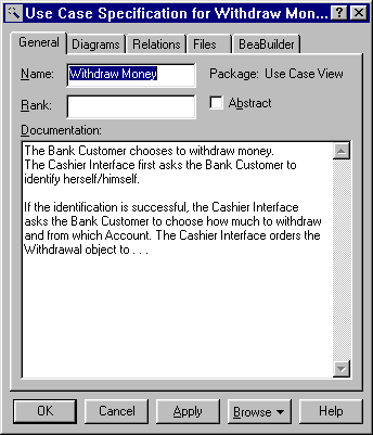
We document each use case with the use case specification tool. Figure 2-3 shows the specification documentation for the Bankapp use case.
Figure 2-3 Specification for the Withdraw Money Use Case
We can also assign additional diagrams to a use case (such as class, sequence, state, and collaboration diagrams).
Now we can convert the use case diagram into an ideal object model using UML stereotypes. To do this, we examine our use case to discover the classes it suggests. Based on this, we create a class diagram to represent the classes and the stereotypes of the classes. (Rational Rose lets you create and assign a class diagram for a use case. We are still working mainly in the Use Case view in this phase.)
Figure 2-4 shows the ideal object model for our Withdraw Money use case. (The ideal object model is distinguished from the more specific implementation model we will build later.) We call our Control Class TellerHandler. The labels Boundary, Control, and Entity indicate the stereotype we associated to each class.
Figure 2-4 Class Diagram Showing the Ideal Object Model (with Stereotypes) for the Withdraw Money Use Case
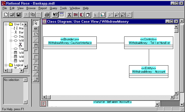
Control classes are typically used to deal with transactions. Generally, these objects do not keep track of information that must be stored between uses of the application-these classes are called handlers in some object-oriented methodologies; or mediators in Design Patterns.
Note that we show relationships between the classes in our ideal object model with association lines. An association line simply indicates that the objects of the two classes will send messages to each other.
In the design phase, we work mainly in the Logical view in Rational Rose to extend the diagrams used in analysis and add information. We also need to make some new diagrams. The focus shifts from the logical relationships between objects to the physical layout of the system. (Note that you do not change the object notation when you move from analysis to design.)
Note: In object oriented development, the class structures and names created during the analysis and design phase become code elements during the coding phase. Because of this, the names you choose during analysis and design should be consistent with how you want code elements named.
For this example, our design phase consists of the following tasks:
Now we can componentize our system model by using packages. The package is a UML construct used to organize a system at a high level. Packages represent the parts or components of a system. In the Rational Rose, a package is "a logical collection of classes and/or other packages." So, we can partition our system model among a set of packages. Each modeling element is owned by exactly one package. References to elements in other packages can be imported, but the definition of each element must exist in just one place. Packages themselves can be part of other packages, with the entire system at the root.
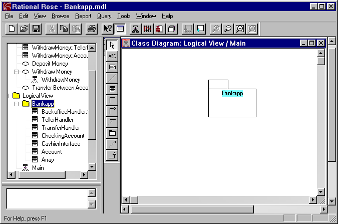
For this example, we create a root package called "Bankapp." Figure 2-5 shows our Package Specification for Bankapp. Figure 2-6 shows the high level class diagram for the package.
Class diagrams contain icons representing classes. Each class diagram provides a logical view of the model, displaying icons representing packages, classes and relationships contained in the model.
You can use object models created during the analysis phase as a basis for class diagrams. During the first iteration phase we concentrate on classes whose stereotype is Control (they link the application tiers and abstract the BEA TUXEDO run time system).
(As already discussed, Figure 2-6 shows the class diagram for our root package, Bankapp.) Logically, the Bankapp package will contain other packages and classes derived from our Bankapp use case. Now we can define the classes within Bankapp.
When we populate the Contract Repository based on this model, the name of each class whose stereotype is "Control" will map to an interface object in the Contract Repository. (For more information on exporting data to the Repository, refer to the section Populating the Repository.)
Classes of stereotype Control should not have attributes defined for them. These classes must be stateless by design to conform to the BEA TUXEDO service programming model.
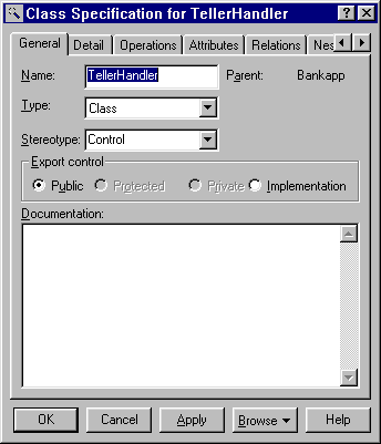
As an example, Figure 2-7 shows the Class Specification for our TellerHandler class, which belongs to the Bankapp module. The
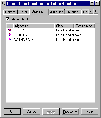
Now we add operations to the classes we just created. Each operation requires a return type of Once we add the operations to a class, the operations show up on the Operations tab of the Class Specification dialog for that class. Figure 2-8 shows the operations for our
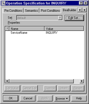
We have the option of specifying a BEA TUXEDO service name for each operation, or accept the default which is the same as the operation name. (To specify the service names, bring up the Operation Specification dialog. In the Operation Specification dialog click on the BEABuilder property tab and enter a valid BEA TUXEDO service name in the ServiceName field.)
A BEA TUXEDO service name can be up to 15 characters in length. Generally, the service name is the same as the operation name. In fact, if you do not enter a name here the BEA TUXEDO service name is assumed to be the operation name.
We also need to specify a signature for each operation. An operation signature is a contract between a service user and provider. The operation signature has specific syntax and semantics that the Rose Expert uses for code generation.
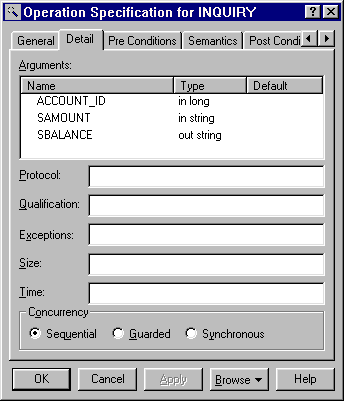
We can specify a signature for an operation on the Detail tab of the Operation Specification. On this tab, we need to provide values for the Arguments fields (Name, Type, and Default) so that the Rose Expert code generation will work properly.
Table 2-1 describes valid values to enter in these fields.
Create Packages and a Class Diagram for the Package
Figure 2-5 Bankapp Package Specification
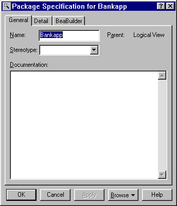
Figure 2-6 High Level "Main" Class Diagram Showing the Bankapp Package
Create Classes and a Class Diagram
Add Classes to the Bankapp Module
TellerHandler class will map to the TellerHandler interface object in the Contract Repository.
Figure 2-7 Class Specification for TellerHandler, General tab
Add Operations to Bankapp's Classes
void and name. These operations map to BEA TUXEDO services at run time. When we export data to the Contract Repository (via the Rose Expert "Populate Repository" features), the operations we create here will map to operations of the same name in the Contract Repository. (For more information on exporting data to the Repository, refer to the section Populating the Repository.)
TellerHandler Class.
Figure 2-8 Class Specification for TellerHandler, Operations tab
Specify the TUXEDO Service Name for Each Operation
Figure 2-9 Specifying the TUXEDO Service Name for an Operation
Specify a Signature for Each Operation
You can run the Rose Expert "Validate Model" process to ensure the operation signature has been entered according to the specifications shown in Table 2-1 above. (The Validate Model process also checks for other Rose Expert specific values in the model.)
It is a good idea to run the Rose Expert Validate Model process immediately after specifying each class so that you can detect errors early. For more information on the Validate Model process, refer to the section Validating a Model.
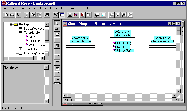
After we have added classes and specified operations for classes of stereotype Control, we can add these to a class diagram within the Bankapp package in the Logical view. This more detailed class diagram looks like the example shown in Figure 2-11.
Arguments in operations can be primitive types or structures. Structures are defined in the model by creating classes with the stereotype "Structure". These classes can then be referenced as argument types.
For a class of stereotype "Structure" the class name will be the structure name. The structure name also maps to the name of the same structure in the Contract Repository. (Refer to Table 3-5 for model-to-repository mappings.) No operations should be defined for this type of class. Structure members are defined as attributes of the class. In order for the Rose Expert code generation to work correctly, these attributes must have specific syntax and semantics as described in Table 2-2.
Figure 2-10 Operation Specification for Inquiry, Detail tab with Arguments
Create the Main Class Diagram within Bankapp
Figure 2-11 "Main" Class Diagram within Bankapp in the Logical View
Structure Classes
A component diagram shows relationships between component packages and components. A component package is a physical package as opposed to logical packages we designed in the previous step.
Components are derived from the following elements: main programs, packages, subprograms, and tasks. Each component diagram provides a physical view of the current model.
Component diagrams contain icons representing:
Create Component Packages and a Component Diagram
For more information about working with component packages and diagrams, refer to the Rational Rose documentation.
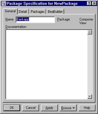
Now we create a new component package for Bankapp in the Component View. (Figure 2-12 shows the component package specification for Bankapp.)
The component package is the unit of generation the Rose Expert will use to generate framework classes and make files for the various control classes and structure classes we have created in Rational Rose.
Once we create the Bankapp component package, we need to design the relationship between our model elements (classes), their specification and implementation modules, and component packages. We can do this by assigning one or more logical packages to a component package. (When you assign a logical package to a component package, the component package becomes the owner of the logical package. At this point, the logical package or its model elements are no longer visible to other component packages.)
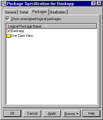
To assign a logical package to a component package, click on the Packages tab in the Component Package Specification dialog, select the package you want to assign, then right mouse click and choose "Assign" from the popup menu. The newly assigned package is displayed with a checkmark beside it.
Figure 2-13 shows the Bankapp logical package listed in the Bankapp component package. Note that the checkmark indicates we have assigned the Bankapp logical package to the Bankapp component package.
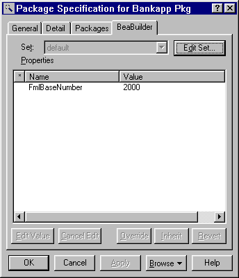
The component package specification is also used to assign the base FML number to use when generating FML field tables. To assign the base FML number, click on the BEABuilder property tab in the Component Package specification dialog and edit the "FMLBaseNumber" field to specify the base number to use for FML field table generation. (The base number is the starting point for generated FML field numbers for this component package.)
If you do not specify the FML base number, the Rose Expert assigns a number for every component package during model validation. The range of FML numbers available for the selected FML buffer type (chosen on the Generation Settings window) is divided by the total number of component packages to arrive at the base number. If a component package has a base number assigned, then the next higher number is chosen for the next unassigned component package. So, assigning a very large value for a component package (but within the valid range) can cause the model validation to fail.
Valid ranges for FML numbers are as shown for the following FML buffer types:
Create the Bankapp Component Package
Figure 2-12 Component Package Specification for Bankapp
Assign the Bankapp Logical Package to Bankapp Component Package
Figure 2-13 Component Package Specification for Bankapp (Showing Bankapp Logical Package Assigned to It)
Specify the Base FML Number
Figure 2-14 Specifying the FML Base Number for the Bankapp Package in the Component View
Now we design and specify modules for our control classes. A task module represents a package with independent threads of control. Each task module represents a BEA TUXEDO server. The task module name maps to the name of a module in the Contract Repository. (Refer to Table 3-5 for model-to-repository mappings.) The control classes are then selected to be included in a task. A module can contain one or more control classes.
To create a task module, use the tool bar to drag the "Task Specification" icon into the Component Diagram within the component package as shown in Figure 2-15.
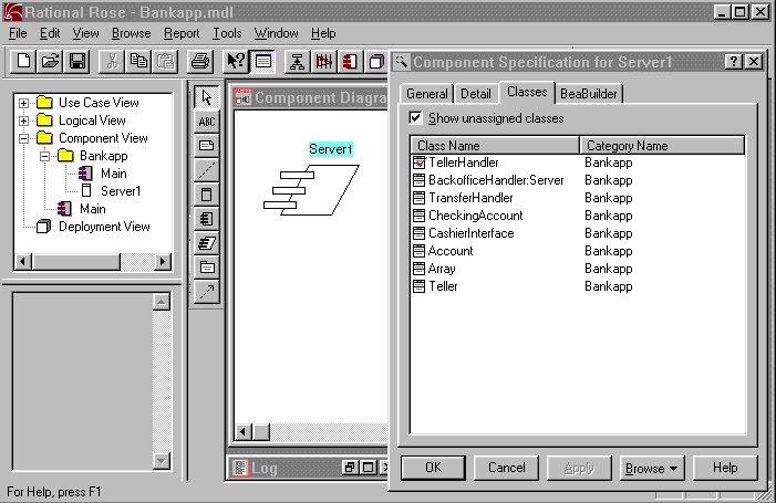
To access the component specification for a task module, double click on the new icon in your diagram. Figure 2-16 shows the Classes tab on the component specification for our Server1 task module along with Server1 task module displayed in the component diagram for Bankapp. Note that we have assigned the logical "TellerHandler" class to Server1. (Right mouse click and choose "Assign" from the popup menu to assign a logical class to a component module.)
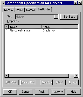
The component package specification is also used to assign the Resource Manager to each Task Module. Rose Expert uses this information for generating the make file.
(To do this, bring up the component specification dialog for the task module, and click on the BEABuilder property tab. Enter a valid Resource Manager name in the ResourceManager field.)
Valid resource manager entries are:
Create a Task Module for Each TUXEDO Server
Figure 2-15 Creating a Task Module Called "Server1"
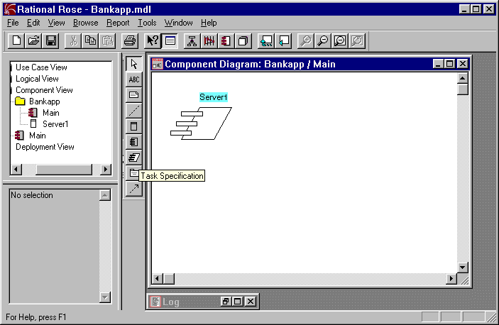
Figure 2-16 Component Package Diagram Reflecting a Task Module Specification for Server1
Specify the Resource Manager for a Task Module
Figure 2-17 Specifying the Resource Manager for a Component
