

|

|
|
|
|
Configuring Power.Enterprise!
This section describes the installation and configuration of Power.Enterprise! and its associated software:
Installing Power.Enterprise!
Power.Enterprise! is delivered in two packages that must be installed separately. In addition, you may want to install Cleo A+ to manage VAN connectivity issues.
If you plan to install both Power.Server! and Power.Client! on the same machine, you must install them in separate directories.
BEA WebLogic Integration includes a 30-day trial license common to all Power.Enterprise! software. To receive a single, full-use license for Power.Server!, contact your BEA sales representative. One Power.Enterprise! license is available for each BEA WebLogic Integration license.
BEA WebLogic Integration includes a 30-day trial license common to all Power.Enterprise! software. Power.Client! uses this license key
http://www.cleo.com/install/peregrine/install.htm
For information about obtaining a production license for Cleo A+, contact Cleo Communications.
Getting Licenses
Whether you download Power.Enterprise! as part of the WebLogic Integration 2.1 installation or install it from CD media, you will need to obtain your Power.Enterprise! 3.0 evaluation license from the BEA website at the following URL:
http://commerce.bea.com/downloads/weblogic_integration.jsp
A Power.Enterprise! production license is provided when you purchase BEA WebLogic Integration. For more information, please contact your BEA sales representative.
In addition, you may download and install a 30-day trial of Cleo A+, for handling VAN connectivity. To convert your trial license to a production license, contact Cleo Communications.
Access to the Get2Connect.Net VAN is included with the BEA WebLogic Adapter for Power.Enterprise!. To use Get2Connect.Net, contact Peregrine Customer Support through their Web site at http://www.peregrine.com/.
Installing the Power.Server!
To install the Power.Server! software, you must fulfill the prerequisites listed in the previous sections of this document. For general information about installing Power.Server!, see Installing the Power.Enterprise! Software in Installing BEA WebLogic Integration.
Installing the Power.Client!
To install the Power.Client! software (specifically Power.Map! and Power.Manager!), you must fulfill the prerequisites listed under Installing Power.Enterprise!. For general information about installing the Power.Client! software, see Installing the Power.Enterprise! Software in Installing BEA WebLogic Integration.
Connecting to Get2Connect.Net
To use Get2Connect.Net, you must have the Power.Enterprise! software installed. You must also have a valid Product Serial Number (PSN) to register as a Get2Connect.Net trading partner. To get a valid PSN, contact BEA Customer Support.
Installing Cleo A+
If you intend to use Cleo A+ for VAN communications, go to the following URL:
http://www.cleo.com/install/peregrine/install.htm
This Web page provides downloadable installation sets for all platforms supported by Power.Server!, as well as installation and user documentation. The downloadable software includes a trial license. For production licensing, contact Cleo Communications.
Downloading Software Updates
Power.Enterprise! is designed to be updated with downloaded software patches from the BEA Customer Service Web site.
To install software patches for Power.Enterprise!:
Updating EDI Document Descriptions
Power.Enterprise! ships with definitions for many standard EDI documents included. BEA will also make new definition sets available through BEA Customer Service.
To install new standards downloaded from the BEA Customer Service Web site:
Power_Server_install_dir\downloads\metadata\
Power_Server_install_dir\downloads\metadata\
Starting Power.Server!
To start Power.Server! on a Windows platform:
To start Power.Server! on a UNIX platform:
Power_Server_Install_Dir/jre/bin
rmiregistry
Power_Server_Install_Dir/bin
start_server.sh
Note: You can verify that the server has started successfully by checking the contents of the Power_Server_Install_Dir/logs/powerserver.log file for the line Translation server started on date, where date reflects the date and time that you started the server.
Connecting to a Server for the First Time
Before you can log in to Power.Manager! or Power.Map!, you must create a Power.Server! connection. Subsequently, you can use the same procedure to connect to other instances of Power.Server!, allowing you to manage multiple instances of Power.Server! from a single console. All connection data is persistent: once you create a connection, it will be available every time you start Power.Manager!.
To create a connection:
Figure 4-1 Power.Manager! Server Connection Dialog Box
Figure 4-2 Power.Manager! Server Add Dialog Box
Figure 4-3 Power.Manager! Server Connection Dialog Box
Configuring Power.Enterprise!
Power.Enterprise! allows you to configure multiple connections to the BEA WebLogic Adapter for Power.Enterprise!. Each connection to the BEA WebLogic Adapter for Power.Enterprise! is defined as a separate RMI connection, either sending data to or receiving data from Power.Enterprise!. All other configuration required by Power.Enterprise! is designed to configure trading partners, maps, external connections, and exchange profiles. When initially configuring Power.Enterprise!, be sure to configure the following entities in the order shown:
Configuring Trading Partners
To use EDI Integration with WebLogic Integration, you must enter your trading partner data into both Power.Enterprise! and WebLogic Integration. No mechanism exists to move trading partner data either to or from Power.Enterprise!, so you any trading partner data registered with WebLogic Integration must also be entered into Power.Enterprise!.
You must create a Power.Enterprise! trading partner profile for every trading partner involved in your transactions, including your own company.
To create a new trading partner:
Figure 4-4 Power.Manager! Server Connection Dialog Box
Figure 4-5 Power.Manager!
Figure 4-6 Company Profile List
For more information about creating and maintaining trading partners, see Chapter 4 of the Power.Manager! User Reference Manual.
Mapping XML and EDI Data
One of the primary goals of Power.Enterprise! is to enable you to manage the translation of messages from a standard data format into a standard EDI message format. To do so, you must create maps between the data format you have selected and the corresponding EDI message. These maps are unidirectional: they operate only in one direction. Thus, if you need to be able to translate data back and forth between a particular XML message format and a specific EDI message format, you must create two maps: one for outbound transformation (XML to EDI) and one for inbound transformation (EDI to XML).
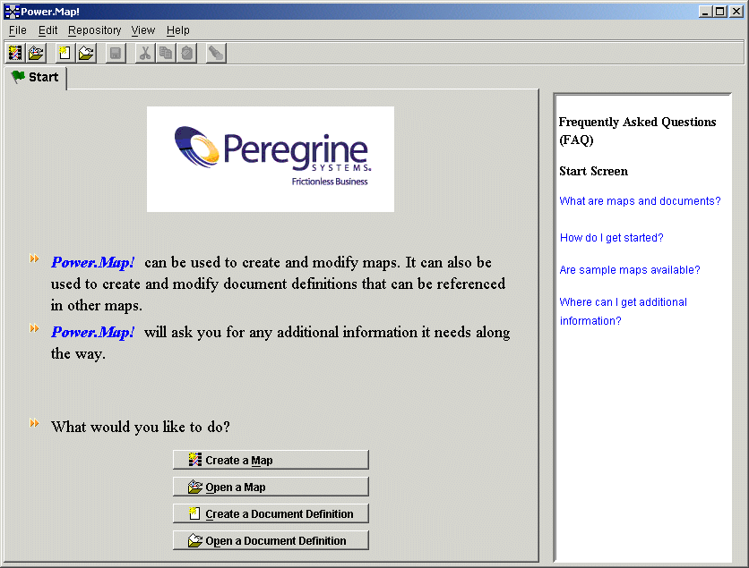
Fortunately, creating such maps is not a difficult task. Power.Map! can understand a variety of standard document definitions, including flat files, database tables, XML, and all the major EDI formats (X12, EDIFACT, and TRADACOMS). As used within Power.Map!, a document definition is an element-by-element description of a document, its structure, and the data carried within it. Thus, you can use standard document definitions to outline your maps, then simply connect the individual data elements between two document definitions using a drag-and-drop interface.
Figure 4-7 Power.Map! Main Window
For more information about creating maps, see the Power.Map! User Reference Manual. You may work on maps without being connected to a Power.Server! instance. If you try to use any repository commands, however, the Server Connection dialog box is displayed, requiring you to connect to a server instance so the repository command can be run. To define a server connection, see Connecting to a Server for the First Time. At any time, you can save a copy of the map you have created on your local system. Choose File Before you can use a map in production, you must promote the map to your server. Select the Finish tab, then click Promote at the bottom of the tab to send the map to the server. If you are not already connected to the server, you must establish a connection before you can promote the map.
Connections and VAN Connectivity
Connections define how message traffic is delivered, both into and out of the Power.Server!. Before you can use the BEA WebLogic Adapter for Power.Enterprise!, you must configure a minimum of four connections:
Two of these connections, the source and target RMI connections, are used to communicate with BEA WebLogic Integration. These two connections are used by all EDI transactions.
Creating RMI Connections
To set up the source and target RMI connections:
Figure 4-8 Power.Manager! Connections List
Figure 4-9 Create New Connection Dialog Box
Figure 4-10 Inbound RMI Properties
Figure 4-11 Outbound RMI Properties
Creating Trading Partner Connections
The other two connections, the inbound and outbound trading partner connections, are specific to each trading partner. Therefore, you must define a unique pair of connections for each trading partner. When you set up each pair, you must select the transport that you and your trading partner will use. We recommend the following transport options:
Other connection options are also available. For details about all options, see Chapter 3 of the Power.Manager! User Reference Manual.
Configuring Exchange Profiles
The exchange profile specifies how a trading partner exchanges messages through Power.Server!. Because Power.Server! is an EDI gateway, it is not the final point of receipt for a message. An exchange profile describes how Power.Server! receives a message, transforms it, and sends it to its destination. For example, an exchange profile might define the receipt of an EDI message from a trading partner, its transformation into an XML message, and its delivery to the BEA WebLogic Adapter for Power.Enterprise!.
Exchange profiles cannot be created unless certain prerequisite information has been defined. Specifically, you must have created and promoted to the server your exchange maps, your trading partner profile, and both the source and target connections. (The source and target connections post messages to Power.Server! and receive messages from Power.Server!, respectively.) For example, to create an exchange profile that allows you to send a message to your trading partner, you need the following:
Other information is also required. For details, see Chapter 4 of the Power.Manager! User Reference Manual. For examples of both inbound and outbound exchange profiles, see EDI Sample, in this document.

|

|

|
|
|
|
Copyright © 2002 BEA Systems, Inc. All rights reserved.
|