VPN Rules Scenario
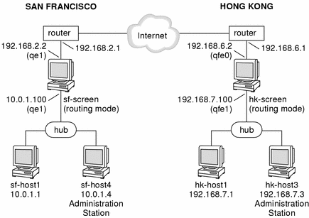
Figure 5-15, shows a VPN connecting the San Francisco and Hong Kong segments of the network. In the diagram, an encrypted tunnel across the Internet exists between Screens sf-screen and hk-screen. The Screens encrypt and decrypt traffic on behalf of the systems behind them, for example sf-host1 and hk-host1.
Figure 5-15 San Francisco and Hong Kong Segments of the Sample Company Network

This network diagram does not really illustrate a scenario where using of VPN rules would enhance convenience. Typically, a scenario including VPN rules would contain a much more complex set of networks on either side. For the sake of brevity, this example only contains two gateways, each with two systems behind them. The steps to create a VPN using VPN rules however would be similar for a VPN with a large number of Gateways and systems.
Using VPN Rules
Configure the VPN
To configure a VPN like the preceding network example, use the following steps:
-
Install the SunScreen software on both Screens .
The two routing-mode Screens in this example are named sf-screen and hk-screen.
-
Add each Screen's certificate object to the other Screen
If the Screens were installed using the SunScreen Installer program, they should already have local SKIP certificates named sf-screen1.cert and hk-screen1.cert, generated when the Administration Stations were set up. If you are using a Screen that does not yet have a certificate, you need to manually generate a SKIP or IKE certificate using the Common Objects panel. See "Create a Certificate Object for Each Screen" in "Basic Encryption Configuration" for an example of creating certificates.
-
Ensure that each Screen includes Address objects for the other Screens and systems.
In this example, you would need to create the following Address objects:
-
hk-screen (should be address for outside IP address of this Screen)
-
sf-screen (should be address for outside IP address of this Screen)
-
hk-host1 (can be part of a group or range)
-
sf-host1 (can be part of a group or range)
-
-
Use the VPN Rules to add entries for the systems in your VPN.
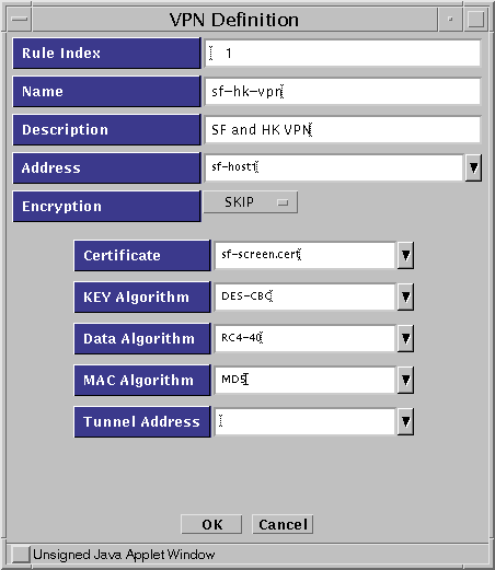
Under Policy Rules, click the VPN tab and add entries for each host in your VPN. This example requires entries for sf-host1 and for hk-host1). Figure 5-16 (SKIP) and Figure 5-17 (IPSEC/IKE) show what the VPN rule definition dialog box might look like when adding the entry for sf-host1.
-
SKIP VPN Definition
Figure 5-16 SKIP VPN Definition Dialog Box

Note -In this example, the entry in the Address field (sf-host1) is a single system. Typically, this entry would be either an address group or an address range defining all the systems on the San Francisco side of the gateway which are going to use encryption.
-
IKE VPN definition
The Name, Address, Encryption, Algorithms, Oakley Group, Authentication Method and Certificate are required for each entry. You specify tunnel addresses on the Options tab.
Figure 5-17 IKE VPN Definition Dialog Box

Once you complete the VPN definitions for sf-host1 and hk-host1, the VPN tab (under the Policy Rules section of the administration GUI) should look like Figure 5-18. Note that the two entries contain the same name (sf-hk-vpn for this example).
Figure 5-18 VPN Tab, Under Policy Rules

Note -All entries associated with a particular VPN must have the same VPN name. The VPN name is referenced again when you create the packet filtering rules. They only accept a packet if both addresses in the IP header are associated with the same VPN.
-
-
Add a new Packet Filtering rule that uses the VPN name:
In this example, the following steps would occur on Screen sf-screen1.
Complete the information as needed, and select VPN as the action.
Note -Use an "*" for the source and destination addresses (at least for testing). This enables any packet that reaches this rule, and has both source and destination in the specified VPN, to be securely sent to the remote site.
-
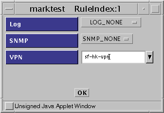
The Action Details window appears and prompts you to supply a VPN.
Enter the VPN name you created in Step 4 (sf-hk-vpn) as shown in the dialog window in Figure 5-19.
Figure 5-19 Initial Rule Index Dialog Box

-
Save and activate the policy.
-
Repeat Step 4, Step 5, and Step 7 on the other Screen (in this example hk-screen. )
-
Test the VPN Gateway.
You can easily test the configuration by creating a VPN packet-filtering rule that enables ICMP traffic to pass through the VPN, and then running a ping between protected hosts (sf-host1 and hk-host1.)
The following examples show the results of running snoop on the network in San Francisco, Hong Kong, and out on the Internet, the results would be as follows:
Inside either the San Francisco or Hong Kong Screen:
sf-host1 -> hk-host1   ICMP Echo request
hk-host1 -> sf-host1   ICMP Echo reply
Outside the Screen on the Internet:
sf-screen -> hk-screen IP D=192.168.6.2 S=192.168.2.2 ...
hk-screen -> sf-screen IP D=192.168.2.2 S=192.168.6.2 ...
- © 2010, Oracle Corporation and/or its affiliates
