| C H A P T E R 1 |
|
Netra CP2500 Board Overview |
The Netra CP2500 board is a crucial building block that network equipment providers (NEPs) and carriers can use when scaling and improving the availability of carrier-grade systems. Based on industry standards, the Netra CP2500 board provides high performance and is powered by a UltraSPARC® IIIi processor. The board enables you to add a third-party PCI mezzanine card (PMC) to tailor solutions to your specific application needs.
When replacing the Netra CP2140 host and Netra CP2160 satellite CompactPCI (cPCI) boards in the Netra CT 410 and 810 servers, the Netra CP2500 board provides a sizeable increase in Netra CT server performance.
The Netra CP2500 board provides PCI Industrial Computers Manufacturers' Group (PICMG) CompactPCI Packet Switched Backplane (cPSB) compliance. To meet the requirements of the communications and service provider environments, the board is NEBS Level 3 compliant, and the Netra CT 410 and 810 servers remain NEBS Level 3 certified with the Netra CP2500 board installed.
This chapter contains the following sections:
The Netra CP2500 board is a single-board computer designed for high-performance, embedded, compute density applications. The Netra CP2500 board has system management controller (SMC) capability that supports hot-swap operations, system management, and environmental monitoring. Powered by a UltraSPARC IIIi processor and including on-board I/O and one PMC slot, the Netra CP2500 board is an ideal platform for NEPs to use for a wide variety of Solaris Operating System applications.
FIGURE 1-1 displays an illustration of a typical Netra CP2500 board, and TABLE 1-1 lists a summary of the board features.

|
Two 184-pin memory slots available for Sun-supplied, 0.72-inch DDR-1 very low-profile (VLP) DIMMs. Total memory capacity is 2 Gbytes using two 1 Gbyte DIMMs. |
|
|
Estimated at 55 W (typical) and 65 W (peak maximum) with a RTM and two 1.0 GByte DIMMs installed.
|
|
|
|
|
The board functions as a cPSB node board in a cPSB chassis with the appropriate Solaris Operating System software installed. |
|
|
The board functions as a system host board when installed in the host slot of a Netra CT 410 or 810 server with the appropriate Solaris Operating System software installed |
|
|
The board functions as a satellite board when installed in Netra CT 410 or 810 server with the appropriate Solaris Operating System software installed. |
|
|
Uses IPMI communications with Baseboard Management Controller (BMC); performs environmental monitoring on local board interface for example temperature sense, FRU ID, and control. |
|
|
Basic and full hot-swap support. High-availability (HA) hot-swap support when used as a cPSB node board, Netra CT 410 or 810 satellite or host cPCI board. |
|
|
CompactPCI rear transition module host card (referred to in this document as RTM-H). The RTM-H is only supported in Netra CT 410 and 810 servers, and contains the following features: |
|
|
CompactPCI rear transition module satellite card (referred to in this document as RTM-S). While in cPCI mode, the RTM-S is supported in Netra CT 410 and 810 servers only. However, you can set mechanical DIP switches on the Netra CP2500 board and the RTM-S card to enable the Netra CP2500 board to be used as a node board in a cPSB chassis: |
|
|
Provision for adding one independent hardware vendor (IHV) supplied PMC expansion ports on front panel. |
|
|
8 Kbyte nonvolatile serial I2c EEPROM (SEEPROM) to save OpenBoot |
|
|
NEBS Level 3 compliant; Netra CT 410 and 810 servers remain NEBS Level 3 certified with installed Netra CP2500 boards installed. |
|
|
Note - Sun does not support installing a PMC interface module (PIM) device on either the RTM-S or the RTM-H. |
|
Note - For EMI compliance of the front access ports, use shielded cables on all I/O ports. The shields for all shielded cables must be terminated on both ends. |
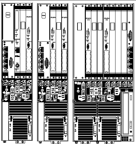
The Netra CP2500 board can be installed in the host or a satellite slot of a Netra CT 410 or 810 CompactPCI server, as shown in FIGURE 1-2 and described in TABLE 1-2. Refer to the Netra CT 410 and 810 server documentation for information about installing and using the Netra CP2500 board in a Netra CT server.
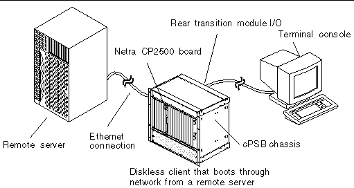
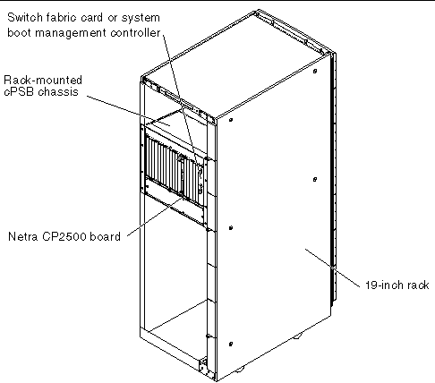
The Netra CP2500 board can also be mounted in various cPSB enclosures, such as those shown in FIGURE 1-3 and FIGURE 1-4.
You can deploy the Netra CP2500 boards in a number of cPSB configurations to suit your specific requirements. For example, the board can be configured to boot from a network as a diskless client over either a cPSB backplane network or an RTM Ethernet network connection. Alternatively, the Netra CP2500 board can be purchased with an installed PMC hard drive, which can provide local disk support I/O and may optionally be used as a boot path. The installation procedure is independent of the type of enclosure, whether a floor-mounting rack or a bench-top cabinet is used.
While the Netra CP2500 board has only one serial port on the front panel, IHV-built PMC modules can provide additional I/O to the front panel. PMC modules decode their custom I/O from the Netra board's on-board PCI bus signals.
|
Note - Sun does not support installing a PMC interface module (PIM) device on either the RTM-S or the RTM-H. |
|
Note - The Netra CP2500 board has one PMC I/O slot. If you purchase a board with a PMC disk drive, you will not be able to install an additional PMC device. |
There are two optional transition modules (RTMs) available for the Netra CP2500 board:
You can install the RTM-H and RTM-S into rear slots of the Netra CT server, opposite the appropriate Netra CP2500 board. These rear transition modules connect with the board's CompactPCI connectors through the Netra CT server midplane pins and carry four Ethernet ports, and two serial ports out to its rear panel. Refer to the Netra CT Server Installation Guide (819-2740) for installation and cabling instructions.
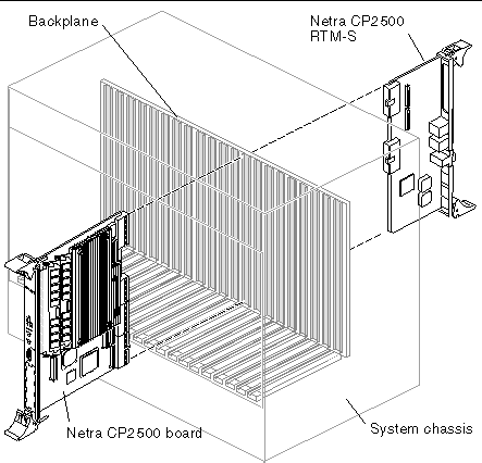
After setting a DIP switch on the Netra CP2500 board and two banks of DIP switches on the RTM-S, you can install the Netra CP2500 board and the RTM-S into a cPSB chassis (see FIGURE 1-7). See Chapter 2 for cPSB chassis installation instructions, including how to set these mechanical switches.
|
Note - For complete information about the two Netra CP2500 rear transition modules, refer to the Netra CP2500 Rear Transition Module Installation and Technical Reference Manual (819-1753). |
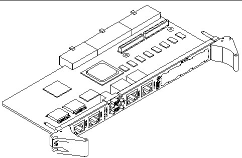
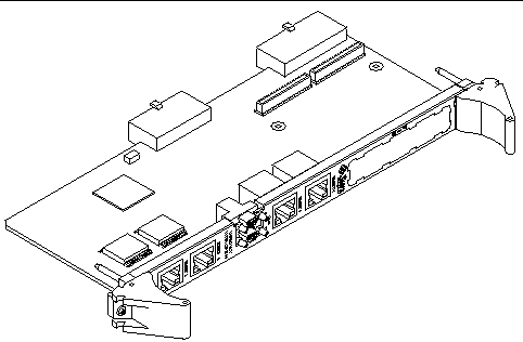
FIGURE 1-7 shows the relationship between the Netra CP2500 board, the RTM-S, and the backplane in a typical cPSB chassis.
The customer can order a Netra CP2500 RTM-S, build a custom card, or buy from an independent hardware vendor (IHV). A minimal set of I/O must provide for a boot path for the host board, and for a path for console I/O to deliver commands and to read board and system status.
TABLE 1-3 describes the possible Netra CP2500 board boot and I/O configurations. Sun Microsystems provide the Netra CP2500 boards and compatible RTMs. These RTMs provide four Ethernet RJ45 ports from the host to the rear of the system. These ports can optionally be used to accomplish a network boot as a diskless client. The other configurations require IHV hardware.
This section briefly discusses the hot-swap support on the Netra CP2500 board.
Refer to the PICMG CompactPCI Hot-Swap Specification, for a detailed description of this subject. In general, the hot-swap process includes the orderly connection of the hardware and software.
This process uses hardware connection control to connect the hardware in an orderly sequence. Hot-swapping uses backplane pins of different lengths to perform signal sequencing, which protects the hardware and avoids corrupting the backplane bus.
There are three models of hot-swap described in the PICMG CompactPCI Hot-Swap Specification - basic hot-swap, full hot-swap, and high-availability (HA) hot-swap.
TABLE 1-4 lists the hot-swap support details when a Netra CP2500 board is installed in a Netra CT 410 or 810 server, or when the board functions as a cPSB node board in a cPSB enclosure.
|
HA Hot-Swap[2] |
|||
|---|---|---|---|
|
Yes[3] |
|||
You can order the following items from Sun:
|
Note - The Netra CP2500 CompactPCI host rear transition module (RTM-H) cannot be ordered separately, but the RTM-H is included the Netra CT 410 and Netra CT 810 Netra CP2500 board upgrade kits. |
Rear transition modules are optional and must be ordered separately from the Netra CP2500 board. Refer to the Netra CP2500 Rear Transition Module Installation and Technical Reference Manual (819-1753) for complete details about installing and using the Netra CP2500 RTMs.
Acquire the following components if needed:
Refer to the Netra CP2500 Rear Transition Module Installation and Technical Reference Manual (819-1753) for descriptions of the RTM I/O connections.
TABLE 1-5 lists additional hardware requirements.
|
cPSB system enclosure for 6U boards (includes chassis, backplane, power supply[4]) |
|

|
Caution - You can damage the Netra CP2500 board components if you install the board in a chassis that does not provide sufficient cooling or has incorrect cPCI I/O voltage (VIO). |
|
Note - If you will be updating the host or satellite CompactPCI boards in a Netra CT 410 or 810 server, refer to the Netra CT Server Upgrade Guide (819-2745) for the hardware requirements. |
Refer to the Netra CP2500 Board Release Notes (819-1748) for Solaris OS information, including a list of the required software patches and where to find installation instructions. You can view and download the latest version of this document at the following web site:
http://www.sun.com/documentation/
The Netra CP2500 board is a 6U circuit board with CompactPCI connectors J1 and J2 for PCI, and J3 and J5 for I/O. The CompactPCI J4 connector is not fitted to the board. See FIGURE 1-8 and FIGURE 1-9 for top and solder-side views of the board.
|
Note - The heat sink is not shown in this diagram to illustrate the components on the board that lie beneath the heat sink. |
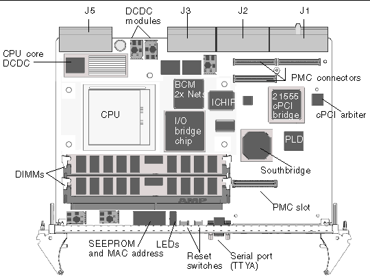
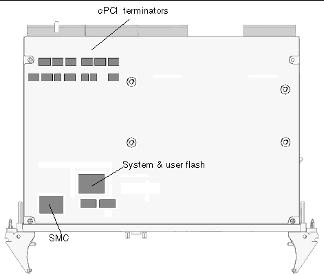
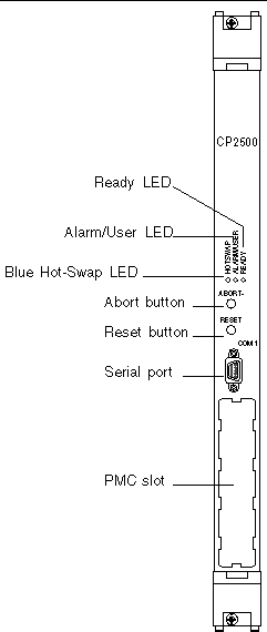
FIGURE 1-10 displays the locations of the Netra CP2500 board front panel LEDs, buttons, serial port, and PMC slot. TABLE 1-6 describes these front panel components.
|
A green LED showing that the board is receiving power, which is sourced from the power module and controlled by the system management controller (SMC). |
|
|
You can define the operation of this yellow LED. The default function of this LED shows that the board is at an OK status. The colors are CPU controlled by way of the SMC. Refer to the Netra CP2500 Board Programming Guide (819-1749) for information on programming the alarm/user LED. |
|
|
A blue LED that shows the hot-swap status of the board. See Section 3.1, Hot-Swap Information for more information about hot-swap operations. Note - The hot-swap LED is in a noncompliant location of the front panel. |
|
|
An abort button, which passes an externally initiated reset (XIR) signal to the SMC when pressed. |
|
|
A reset button, which passes an power-on-reset (POR) signal to the SMC when pressed. |
|
|
One micro DB9 connector is available for serial port (TTYA) I/O. This port can only be used if rear serial port COM A is not being used. |
|
|
One peripheral mezzanine card (PMC) slot is available for additional I/O. |
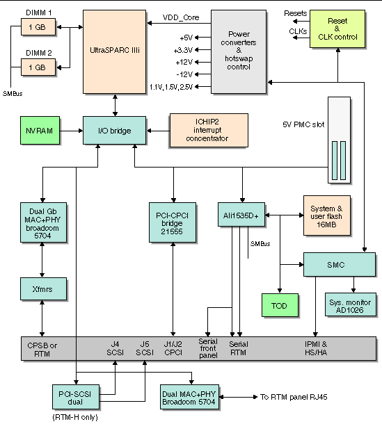
FIGURE 1-11 displays a simplified schematic diagram of the Netra CP2500 board.
Should you have any technical questions or support issues that are not addressed in the Netra CP2500 documentation set or on the web site, contact your local Sun Services representative. Find the World Wide Solution Center nearest you by visiting our web site:
http://www.sun.com/service/contacting/solution.html
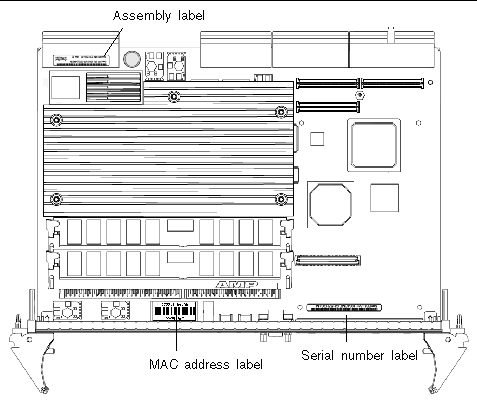
When you call Sun Services, be sure to indicate if the Netra CP2500 board was purchased separately and is not associated with a system. Please have your Sun support contract number and the board identification information ready when you call. For proper identification of the board be prepared to give the representative the board part number, serial number, and board revision level (see FIGURE 1-12).
The Netra CP2500 board can be identified by the barcode labels placed on the board (see FIGURE 1-12). You will need to locate the following labels to identify the board properly:
|
Note - You might find the labels shown in FIGURE 1-12 on other locations on your board. Also, your board configuration might appear different than shown in the preceding illustration. |
Copyright © 2007, Sun Microsystems, Inc. All Rights Reserved.