| C H A P T E R 2 |
|
Installing the Netra CP2500 Board in a cPSB Chassis |
This chapter describes how to install a Netra CP2500 board hardware in a cPSB chassis.
|
Note - This chapter does not describe how to install the board in a Netra CT 410 or 810 server, or how to replace a Netra CP2300 cPSB board installed in a cPSB chassis. See Section 2.1, Installation Options for more information. |
This chapter contains the following sections:
This chapter describes how to install the Netra CP2500 board in a cPSB chassis. TABLE 2-1 lists other installation options and where you can find the installation procedures.
You can download PDF and HTML versions of Sun documentation at the following web site:
http://www.sun.com/documentation/
Refer to the Important Safety Information for Sun Hardware Systems (816-7190) for general safety information.
Read these safety statements specific to the Netra CP2500 board carefully before you install or remove any part of the system.
The installer must be familiar with commonly-accepted procedures for integrating electronic systems and with the general practice of Sun systems integration and administration. Although parts of these systems are designed for hot-swap operation, other components must not be subjected to such stresses. Work with power connected to a chassis only when necessary and follow these installation procedures to avoid equipment damage.
This equipment is sensitive to damage from electrostatic discharge (ESD) from clothing and other materials. Use the following antistatic measures during an installation:
Connect the other end of the strap lead to one of the following:
This section provides information on the materials and tools required to perform installation. The minimum tools required to perform installation are:
Refer to Section 1.4.1, Hardware Requirements for information on hardware requirements.
Read the following subsections before starting to install these boards. In addition, do the following:
1. Become familiar with the contents of the referenced documentation.
2. Verify that all listed hardware and software is available (see Section 1.4, System Requirements).
3. Check power, thermal, environmental, and space requirements (see Section 2.4.1, Checking Power, Thermal, Environmental, and Space Requirements).
4. Verify that local area networking (LAN) preparations are completed (see Section 2.4.2, Determining Local Network IP Addresses and Hostnames).
5. Ensure that the host names and their network IP addresses are allocated and registered at the site.
Collect the following information to connect hosts to the local area network (LAN). Ask your network administrator for help, if necessary. This information is not needed for a standalone installation. You can use TABLE 2-2 to record this information.
|
IP addresses[1] and hostname for each Netra CP2500 client |
|
|
Type of name service and corresponding name server names and IP addresses - for example, DNS and NIS (or NIS+) |
|
You might need the MAC addresses of the local hosts to make nameserver database entries. The MAC address can be seen in the console output while booting to the ok prompt. It can also be derived from the host ID seen on the barcode label of the SEEPROM (see Section 1.6.1, Board Identification).
|
Note - This chapter does not describe how to install the board in a Netra CT 410 or 810 server, or how to replace a Netra CP2500 cPSB board installed in a cPSB chassis. See Section 2.1, Installation Options for more information. |
This section summarizes the Netra CP2500 board installation at a high level. Ensure that you read the details in Section 2.5, Configuring the Board Hardware through Chapter 3 before installing the board.
The process to set up and configure a Netra CP2500 board in a cPSB chassis includes the following steps:
1. Configure the board's physical hardware.
For example, install the PMC card, replace the SEEPROM (if required), and set DIP switches if necessary.
2. If your environment requires rear access to connect cables, configure and install the RTM-S module.
a. Configure the RTM-S module.
For example, set DIP switch settings or prepare connector attachments, as necessary.
b. Physically install the RTM-S.
3. Physically install the Netra CP2500 board, and any peripheral boards, into the chassis.
4. Connect the node(s) to a local network. Alternatively, the board can be run as a standalone system without a network connection.
5. Install the Solaris Operating System.
This section lists hardware installation and settings that might apply for your board configuration. Read and perform the procedures, as necessary, before installing the Netra CP2500 board into a cPSB chassis.
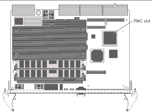
A PCI mezzanine card (PMC) is a slim, modular mezzanine card that provides additional functionality to the Netra CP2500 board. The board contains one PMC slot in which you can install an optional PMC device (see FIGURE 2-1 for the location of the slot). You must install PMC devices on the Netra CP2500 board before you install the board into the chassis.
|
Note - Before installing the PMC device, ensure that the device is keyed to 5V, or is set to universal voltage. |
1. Retrieve the wrist strap from the adapter's shipping kit.
2. Attach the antistatic wrist strap:
a. Attach the adhesive copper strip of the wrist strap to the metal chassis.
b. Wrap the other end twice around your wrist, with the adhesive side against your skin.
3. Remove the Netra CP2500 board from its antistatic envelope and place it on an ESD mat (if one is available) near the chassis.
If an ESD mat is not available, you can place the card on the antistatic envelope it was packaged in.
|
Note - If EMI compliance is required, do not remove the PMC filler panel unless you are going to install a PMC on the board. |
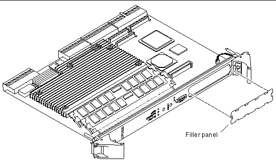
4. If the PMC has a connector for cabling, or if the PMC has a faceplate that fits in the Netra CP2500 board's faceplate, remove the board's filler panel (FIGURE 2-2).
Depending on its application, a PMC might contain a connector where you need to attach a PMC-specific cable, or it might have LEDs that must be viewed while the operating. If the PMC has a connector, LEDs, or a protruding faceplate, remove the board's filler panel.
5. Retrieve the PMC from its shipping kit and place it on an antistatic surface.
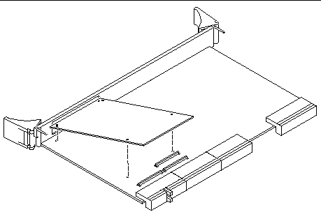
6. Insert the PMC at an angle into the appropriate PMC slot (FIGURE 2-3).
Ensure that the PMC's connector goes through the board's PMC slot.
7. Align the PMC over the PMC connectors.
8. Carefully press the PMC into the board's PMC connectors (FIGURE 2-4).

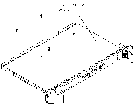
9. Turn the Netra CP2500 board over and use a No. 1 screwdriver to secure the four screws that attach the PMC to the Netra CP2500 board (FIGURE 2-5).
Refer to the PMC device's documentation for PMC software and cabling installation instructions.
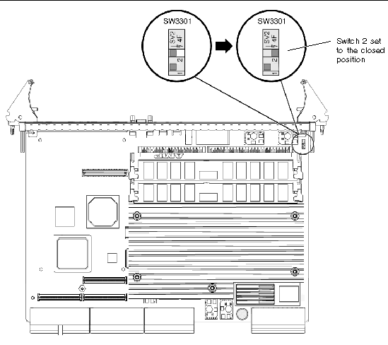
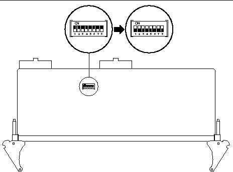
Switch 2 of the SW3301 DIP switch bank selects whether the board will operate in a Netra CT 410 or 810 CompactPCI server or in a cPSB chassis. By default, this switch is set so that the board will operate in a Netra CT 410 or 810 server. Prior to installing the Netra CP2500 board into a cPSB chassis, you must change the setting of this switch so that the board will operate in a cPSB chassis.
|
Note - See Section B.4, DIP Switch Settings, for further details about the Netra CP2500 board switch settings. |
To Set SW3301 Switch 2 to cPSB operation:
1. Retrieve the wrist strap from the adapter's shipping kit.
2. Attach the antistatic wrist strap:
a. Attach the adhesive copper strip of the wrist strap to the metal chassis.
b. Wrap the other end twice around your wrist, with the adhesive side against your skin.
3. Remove the Netra CP2500 board from its antistatic envelope and place it on an ESD mat (if one is available) near the chassis.
If an ESD mat is not available, you can place the card on the antistatic envelope it was packaged in.
4. Using a needle, metal pick, scribe tool, or a small screwdriver, set switch 2 from the open position (in the direction opposite of the arrow on the switch) to closed (in the direction of the arrow).
The SW3301 DIP switch bank is located on the component side of the board between the front panel and heat sink (see FIGURE 2-6). FIGURE 2-6 displays how to set switch 2 from the open to closed position.
The SEEPROM stores the board MAC address and host ID information. You do not need to replace the SEEPROM unless you are installing a replacement board that does not have the correct host ID information.
If you need to replace the Netra CP2500 board, remove the SEEPROM from the original board and install it on the replacement Netra CP2500 board.
1. Retrieve the wrist strap from the adapter's shipping kit.
2. Attach the antistatic wrist strap:
a. Attach the adhesive copper strip of the wrist strap to the metal chassis.
b. Wrap the other end twice around your wrist, with the adhesive side against your skin.
3. Remove the Netra CP2500 board from its antistatic envelope and place it on an ESD mat (if one is available) near the chassis.
If an ESD mat is not available, you can place the card on the antistatic envelope it was packaged in.
4. Locate the MAC address label on the board.
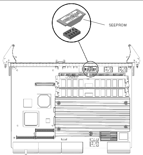
The MAC address label is located between the board's faceplate and the memory connectors (see FIGURE 2-7). The MAC address label is fastened on a plastic carrier that protects the SEEPROM.
5. Carefully lift the plastic SEEPROM carrier off of the board (see FIGURE 2-7).
Removing the plastic contain will also remove the board's SEEPROM.
6. Locate the SEEPROM that you removed from the original, defective board you returned to Sun Services.
The SEEPROM should still be encased in its protective plastic carrier with its MAC address label attached.
7. Carefully press the SEEPROM carrier on the board.
If you are using the Netra CP2500 RTM-S, refer to the Netra CP2500 Rear Transition Module Installation and Technical Reference Manual (819-1753). You might also want to refer to this RTM manual for detailed connector pin assignments.
|
Note - An RTM is not required to operate Netra CP2500 board. However, an RTM is needed if you will be connecting cables to the rear of the system or chassis. |
Two rear transition modules are available from Sun for the Netra CP2500 board - the RTM-H and the RTM-S. The RTM-H is designed to be operated solely in the host CompactPCI slot of the Netra CT 410 and 810 servers. The RTM-H will not operate in a cPSB chassis, and it is not supported in any other CompactPCI server.
The RTM-S card can operate in either a Netra CT 410 or 810 server satellite slot or in a node slot of cPSB chassis. When installing a Netra CP2500 board into a cPSB chassis, you must use either this RTM-S or a custom-designed RTM.
The Netra CP2500 RTM-S contains two DIP switch banks that must be set prior to installing the card into the cPSB chassis. These switch banks control whether the Ethernet network traffic of the board is routed to the RJ45 connectors on the RTM-S or whether the RTM-S runs in cPSB mode and the Ethernet network traffic is routed to the cPSB backplane. By default, these switch banks are set to route the traffic to the RJ45 connectors. Therefore, before installing the RTM-S into a cPSB chassis, set these switches to cPSB network operation.
|
Note - For additional information about these DIP switch settings, refer to the Netra CP2500 Rear Transition Module Installation And technical Reference Manual (819-1753). |
To set the RTM-S DIP switches to cPSB network operation:
1. Retrieve the wrist strap from the adapter's shipping kit.
2. Attach the antistatic wrist strap:
a. Attach the adhesive copper strip of the wrist strap to the metal chassis.
b. Wrap the other end twice around your wrist, with the adhesive side against your skin.
3. Remove the Netra CP2500 RTM-S from its antistatic envelope and place it on an ESD mat (if one is available) near the chassis.
If an ESD mat is not available, you can place the card on the antistatic envelope it was packaged in.
4. Locate the S1301 DIP switch bank on the component side of the RTM-S (see FIGURE 2-8).
By default, all of the switches in the S1301 bank will be set to On.
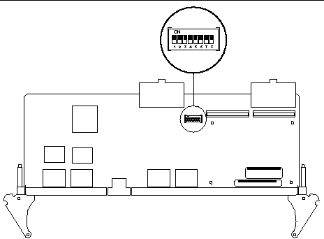
5. Using a needle, metal pick, scribe tool, or a small screwdriver, set all eight S1301 DIP switches to the Off position (see FIGURE 2-9).

6. Carefully flip the RTM-S over to show its solder side and locate the S1302 DIP switch bank (see FIGURE 2-10).
By default, all of the switches in the S1302 bank will be set to On.
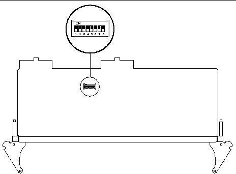
7. Using a needle, metal pick, scribe tool, or a small screwdriver, set all eight S1302 DIP switches to the Off position (see FIGURE 2-11).
This section describes the installation of the RTM-S and the Netra CP2500 board into an example cPSB system chassis. Refer to your cPSB chassis documentation for specific node board installation procedures.
If you will connect cables to the rear of the cPSB chassis, use a compatible RTM with the Netra CP2500 board. The Netra CP2500 RTM-S module provides rear I/O access and enables access to the network, to a boot device, and to a console terminal. You may use the Netra CP2500 RTM-S, or you may design your own RTM.
Refer to the installation procedure in the Netra CP2500 Rear Transition Module Installation and Technical Reference Manual (819-1753) to install the Netra CP2500 RTM-S.
|
Note - If the system power is on when installing the Netra CP2500 RTM-S, the RTM-S must be installed before you install the Netra CP2500 board. |
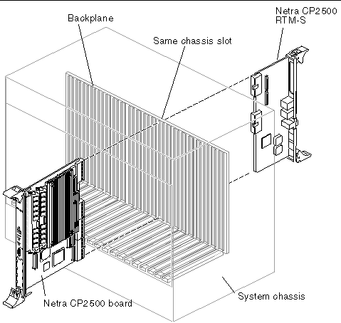
A cPSB chassis usually contains:
1. Ensure that power is disconnected from the chassis.
The Netra CP2500 board can be installed while the chassis is powered, however only start with a powered chassis if necessary. Check that the corresponding Netra CP2500 RTM is installed.
|
Note - If you need an RTM for I/O for the Netra board, ensure that it is already present in the chassis. This step is essential if the chassis is powered during the installation. |
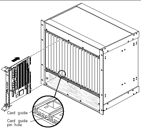
2. Slide the Netra CP2500 board into the appropriate slot on the corresponding top and bottom mounting rails, and toward the backplane while gently pushing the board levers inward.
While sliding the board, ensure that the Netra CP2500 ejector levers are aligned perpendicular to the card flange in the unlocked position and that the board connectors are aligned with the RTM connectors (FIGURE 2-13).
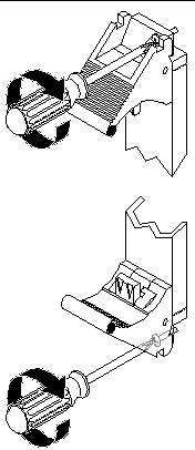
3. Install two screws through the top and bottom of the front connector plate to secure the board (see FIGURE 2-14).
|
Note - Follow the chassis manufacturer's instructions to make sure the Netra CP2500 board is properly installed into the chassis slot. |
This section describes how to set up a system that contains the Netra CP2500 board.
1. Using a category 5 grade network cable, connect one RJ45 connector into the receptacle of a chassis Ethernet fabric card or in the receptacle of the Netra CP2500 board's RTM.
The other end must be connected to a suitable Ethernet hub on the local subnet.
|
Note - Use shielded cables for Ethernet ports on the RTM. Ensure that the shield is grounded at both ends. |
2. Connect I/O cabling to the host board and to the serial port of the host system.
3. Connect a serial cable to the TTYA port on the front panel of the Netra CP2500 board or the Netra CP2500 RTM of the target machine, and to the serial port of the host machine.
4. Use the Tip utility on the host system to establish a full-duplex terminal connection with the Netra CP2500 board.
5. At the UNIX prompt in a command tool or shell tool, type:
|
Note - In order for the Netra CP2500 board to power on, the cPSB chassis must contain a management controller board. |
1. Power on the chassis that contains the Netra CP2500 board.
The board will run power-on self-tests (POST). For additional details on using POST, see Chapter 4.
2. After running POST, install the Solaris Operating System on the Netra CP2500 board.
Refer to the Netra CP2500 Board Release Notes (819-1748) for information about the software installation and patch information.
To boot from a PMC disk installed on the Netra CP2500 board, you will need to change the default boot device from the OpenBoot PROM prompt.
To boot from the PMC disk, use the setenv command to change the boot-device parameter. The following is an example of the setenv command and output.
Where pmc0 corresponds to a disk installed in the PMC slot.
If the installed firmware version is not current, update the OpenBoot PROM before continuing with the board installation (see Section 2.8.4, Upgrading the OpenBoot PROM and SMC Firmware).
To determine the installed OpenBoot PROM version, use the .version OpenBoot PROM command at the ok prompt. See the following example for typical .version command output.
ok .version Release 4.x.y created 2005/10/17 09:40 OBP 4.x.y 2005/10/17 09:40 Netra(tm) CP2500 OBDIAG 4.x.y 2005/08/06 10:28 POST 4.x.y 2005/09/06 10:51 ok |
To determine the installed SMC firmware version, use the .properties command at the OpenBoot PROM prompt. See the following example for typical .properties command output.
Use the prtconf command at a Solaris terminal prompt to display the OpenBoot PROM firmware version of the board.
Use the prtpicl command at a Solaris terminal prompt to display the SMC firmware version of the board.
The board's firmware can be upgraded using a patch downloaded from the SunSolvesm web site. The Netra CP2500 board firmware patch contains the binary files for both the SPARC OpenBoot PROM firmware and the SMC firmware. The FWupdate installation tool enables you to update the firmware while the board is running the Solaris Operating System.
1. Download the latest Netra CP2500 board firmware updates from the SunSolve web site.
Contact your Sun Services representative for information about the latest Netra CP2500 firmware patch.
2. Ensure that the board has booted and is running the Solaris Operating System.
If your Netra CP2500 board is currently running the Solaris Operating System, skip to the next step. Otherwise, type the following at the board's OpenBoot PROM ok prompt to boot the operating system:
3. After the board has booted the Solaris Operating System, open a terminal window and log into the board as superuser.
See Section 2.7, Setting Up an Assembled Netra CP2500 Board, for instructions on logging into the board.
4. Change directories to directory where you extracted the firmware patch.
For example, if you extracted the files to /var/tmp, type:
Where patch_number is the number and revision of the firmware patch.
5. Use the FWupdate tool to update the SPARC® OpenBoot PROM and SMC firmware.
Use the full path and file name of the firmware binaries when updating the firmware. The /var/tmp directory is shown in the following examples.
Where patch-number is the name of the patch and revision is the OpenBoot PROM firmware level.
Where patch_number is the name of the patch and revision is the OpenBoot PROM firmware level.
|
Note - For more information about using the FWupdate tool, refer to the README file included with the firmware patch. |
6. Reboot the Netra CP2500 board to make the new firmware version effective.
Refer to your server or chassis documentation for specific instructions on rebooting the board in your environment.
Copyright © 2007, Sun Microsystems, Inc. All Rights Reserved.