C H A P T E R  4

Configuring and Using the Netra CP2500 Board Firmware

The Netra CP2500 board contains a modular firmware architecture that enables you to customize the initialization, test the firmware, and enable the installation of an operating system.

This platform also employs the system management controller (SMC), which controls the system management and hot-swap control, and some board hardware. The SMC configuration is controlled by separate firmware.

This chapter contains the following sections:


4.1 Firmware Initialization

Control flow at board startup is shown in FIGURE 4-1. Execution begins in the OpenBoot PROM. If you set the diag-switch? environmental variable to true (see Section 4.2, Firmware Configuration Variables for more information), power-on self-tests (POST) will be run at startup.
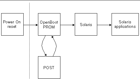

FIGURE 4-1 Control Flow From Power On for Firmware

Figure showing the firmware control flow of the board.


4.1.1 OpenBoot PROM Operation

The OpenBoot PROM probes for devices and builds the device tree, which is a table that contains entries for how drivers communicate with connected hardware. Each line, or entry, of the device tree is a reference for the node entry for the peripheral in the /dev directory. The device tree is inherited by Solaris software as it is booted. The device tree can be seen by directory in the / directory. The device tree can be seen by typing show-devs at the ok prompt. CODE EXAMPLE 4-1 shows an example of a device tree.


CODE EXAMPLE 4-1 OpenBoot PROM show-devs Command Output

ok show-devs
/console
/i2c@1f,464000
/pci@1f,700000
/ppm@1e,0
/pci@1e,600000
/memory-controller@0,0
/SUNW,UltraSPARC-IIIi+@0,0
/multiplexer@0,0
/virtual-memory
/memory@m0,0
/aliases
/options
/openprom
/chosen
/packages
/i2c@1f,464000/idprom@0,ae
/i2c@1f,464000/nvram@0,ae
/pci@1f,700000/network@3,1
/pci@1f,700000/network@3
/pci@1f,700000/scsi@2,1
/pci@1f,700000/scsi@2
/pci@1f,700000/network@1,1
/pci@1f,700000/network@1
/pci@1f,700000/scsi@2,1/tape
/pci@1f,700000/scsi@2,1/disk
/pci@1f,700000/scsi@2/tape
/pci@1f,700000/scsi@2/disk
/pci@1e,600000/pci@1
/pci@1e,600000/isa@7
/pci@1e,600000/pmu@6
/pci@1e,600000/pci@1/pci@11
/pci@1e,600000/pci@1/pci@10
/pci@1e,600000/pci@1/pci@11/SUNW,isptwo@4
/pci@1e,600000/pci@1/pci@11/SUNW,isptwo@3
/pci@1e,600000/pci@1/pci@11/SUNW,qfe@1,1
/pci@1e,600000/pci@1/pci@11/pci108e,1000@1
/pci@1e,600000/pci@1/pci@11/SUNW,qfe@0,1
/pci@1e,600000/pci@1/pci@11/pci108e,1000@0
/pci@1e,600000/pci@1/pci@11/SUNW,isptwo@4/st
/pci@1e,600000/pci@1/pci@11/SUNW,isptwo@4/sd
/pci@1e,600000/pci@1/pci@11/SUNW,isptwo@3/st
/pci@1e,600000/pci@1/pci@11/SUNW,isptwo@3/sd
/pci@1e,600000/pci@1/pci@10/SUNW,isptwo@3
/pci@1e,600000/pci@1/pci@10/SUNW,qfe@1,1
/pci@1e,600000/pci@1/pci@10/pci108e,1000@1
/pci@1e,600000/pci@1/pci@10/SUNW,qfe@0,1
/pci@1e,600000/pci@1/pci@10/pci108e,1000@0
/pci@1e,600000/pci@1/pci@10/SUNW,isptwo@3/st
/pci@1e,600000/pci@1/pci@10/SUNW,isptwo@3/sd
/pci@1e,600000/isa@7/serial@0,2e8
/pci@1e,600000/isa@7/serial@0,3f8
/pci@1e,600000/isa@7/rtc@0,70
/pci@1e,600000/isa@7/flashprom@2,0
/pci@1e,600000/isa@7/ipmc@0,320
/pci@1e,600000/isa@7/ipmc@0,320/i2c@5
/pci@1e,600000/isa@7/ipmc@0,320/i2c@5/rtm-fru-prom@7,a0
/pci@1e,600000/isa@7/ipmc@0,320/i2c@5/hardware-monitor@5,5c
/pci@1e,600000/isa@7/ipmc@0,320/i2c@5/motherboard-fru-prom@5,a4
/pci@1e,600000/pmu@6/gpio@80000000,8a
/pci@1e,600000/pmu@6/i2c@0,0
/pci@1e,600000/pmu@6/i2c@0,0/dimm-spd@0,a2
/pci@1e,600000/pmu@6/i2c@0,0/dimm-spd@0,a0
/openprom/client-services
/packages/SUNW,asr
/packages/SUNW,fru-device
/packages/SUNW,i2c-ram-device
/packages/obp-tftp
/packages/kbd-translator
/packages/console-pkg
/packages/dropins
/packages/terminal-emulator
/packages/disk-label
/packages/deblocker
/packages/SUNW,builtin-drivers 
 

The OpenBoot PROM also contains aliases for some of the devices shown in the device tree. These aliases can simplify hardware access at the ok prompt. CODE EXAMPLE 4-2 shows how the OpenBoot devalias command lists the available device tree aliases.


CODE EXAMPLE 4-2 OpenBoot PROM devalias Command Output

ok devalias
output-mux               /multiplexer:output
input-mux                /multiplexer:input
ipmi-console             /console
ssp-serial               /console
ttyi                     /console
ipmc                     /pci@1e,600000/isa@7/ipmc@0,320
hsc                      /pci@1e,600000/isa@7/ipmc@0,320
net2                     /pci@1f,700000/network@1,1
net                      /pci@1f,700000/network@1
disk2                    /pci@1f,700000/scsi@2,1/disk@0,0
cdrom2                   /pci@1f,700000/scsi@2,1/cdrom@2,0:f
scsi2                    /pci@1f,700000/scsi@2,1
disk                     /pci@1f,700000/scsi@2/disk@0,0
cdrom                    /pci@1f,700000/scsi@2/cdrom@2,0:f
scsi                     /pci@1f,700000/scsi@2
ide                      /pci@1e,600000/ide@4
ttyb                     /pci@1e,600000/isa@7/serial@0,2e8
ttya                     /pci@1e,600000/isa@7/serial@0,3f8
name                     aliases 


4.2 Firmware Configuration Variables

This section provides information on the firmware configuration variables, which are saved in the 8 Kbyte SEEPROM. The SEEPROM's contents are preserved across board power-cycles.

4.2.1 OpenBoot PROM Configuration Variables

TABLE 4-1 describes the OpenBoot PROM configuration variables stored in the NVRAM and displayed by the OpenBoot PROM printenv command. Use the setenv OpenBoot command to modify the environment variables. The boot process is controlled by several variables. For the values of each variable, refer to the OpenBoot 4.x Command Reference Manual, which is included with the Solaris documentation.


TABLE 4-1 OpenBoot PROM NVRAM Configuration Variables

Variable Name

Default Value

Description

ansi-terminal

true

When true, uses an ANSI terminal.

asr-policy

normal

Defines the Automatic system recovery (ASR) policy for the asr-package.

  • normal - user-disabled devices cannot be used
  • service - user-disabled devices will be used

auto-boot-on-error?

false

If variable is set to true, the board will attempt to reboot if a firmware error occurs.

auto-boot?

true

If variable is set to true, the board boots automatically after a power-on reset.

boot-command

boot

Command that is executed if auto-boot? is set to true.

boot-device

disk net

Device from which to boot.

boot-file


File from which to boot (an empty string lets the secondary boot choose the default).

cpci-probe-list

0,1,2,3,4,5,6,7,8,9,a,b, . . .

Defines the probe list for devices present on CompactPCI bus.

diag-device

net

Device from which to boot.

diag-file


File from which to boot in diagnostic mode.

diag-level

max

Sets the level of diagnostics to run (max or min).

diag-out-console

false

Reserved.

diag-passes

1

Repeat each diagnostic test the number of times specified.

diag-script

normal

Determines which devices are tested by OpenBoot diagnostics.

diag-switch?

false

If variable is set to true, POST is executed when system is next powered on.

diag-trigger

none

Reserved.

error-reset-recovery

sync

Command to execute following a system reset generated by an error.

fcode-debug?

false

OpenBoot PROM debug variable.

input-device

ttya

Input device used at power-on (usually keyboard, TTYA, or TTYB).

load-base

16384

Base address where the client image is loaded by the OpenBoot PROM.

local-mac-address?

false

If variable is set to true, network drivers use the board's MAC address, and not the system's address.

multiplexer-input-devices

ttya ttyi

Default input console multiplexer (mux) devices.

multiplexer-output-devices

ttya ttyi

Default output console multiplexer (mux) devices.

network-boot-arguments

Sets NVRAM arguments for network booting.

nvramrc

Contents of the NVRAMRC.

oem-banner

No default

Custom OEM banner (enabled by oem-logo? true).

oem-banner?

false

If variable is set to true, uses custom OEM banner.

oem-logo

No default

Byte array custom OEM logo (enabled by oem logo? true); displayed in hexadecimal numbers.

oem-logo?

false

If true, uses custom OEM logo, otherwise, uses Sun logo.

output-device

ttya

Console output device (usually a screen, TTYA, or TTYB).

screen-#columns

80

Screen width in columns.

screen-#rows

34

Screen height in rows.

scsi-initiator-id

7

Sets the SCSI bus address of host adapter, with a range of 0-7.

security-#badlogins

No default

OpenBoot PROM internal use.

security-mode

No default

Firmware security level (none, command, or full).

  • none: no password required.
  • command: all commands except for boot and go require password.
  • full: all commands except for go require password.

security-password

No default

Set the firmware security password (never displayed).

service-mode?

false

Reserved.

test-args

Sets configuration arguments for POST and OpenBoot diagnostics tests.

ttya-ignore-cd

true

If variable is set to true, the operating system ignores TTYA carrier-detect.

ttya-mode

9600,8,n,1,-

TTYA settings (baud, #bits, parity, #stop, handshake).

ttya-rts-dtr-off

false

If variable is set to true, the operating system does not assert DTR and runs on TTYA.

ttyb-ignore-cd

true

If variable is set to true, the operating system ignores TTYB carrier-detect.

ttyb-mode

9600,8,n,1,-

TTYB settings (baud, #bits, parity, #stop, handshake).

ttyb-rts-dtr-off

false

If variable is set to true, the operating system does not assert DTR and runs on TTYB.

use-nvramrc?

false

If variable is set to true, executes commands in NVRAMRC during the board start-up.

verbosity

min

Sets the amount and detail of firmware message output. Can be set to min, normal, or max.


Note - The diag-switch? and diag-level variables listed in TABLE 4-1 affect the path through the various embedded tests.


4.3 System Flash PROM Memory Map

The node board boots from the 2 Mbyte system flash PROM device, which contains the POST code and OpenBoot PROM. The contents map of this PROM is shown in FIGURE 4-2.
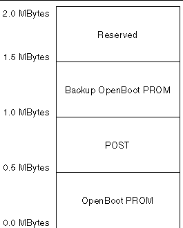

FIGURE 4-2 System Flash PROM Map

Figure showing the system flash PROM memory map.


4.4 Environmental Monitoring Support at OpenBoot PROM

The Netra CP2500 board has an intelligent fault detection environmental monitoring system to increase uptime and manageability at OpenBoot PROM. The system management controller (SMC) module on the Netra CP2500 board supports the temperature monitoring functions. Environmental monitoring tracks the following at regular intervals at the ok prompt:


Note - Refer to the Netra CP2500 Board Programming Guide (817-1331) for additional information about the environmental monitoring features of the Netra CP2500 board.


4.4.1 CPU Thermal Sensor

At the OpenBoot PROM level, when an overtemperature condition occurs, corresponding messages are displayed on the console. The OpenBoot PROM displays the warning messages as soon as the board temperature reaches the warning temperature and is still below the critical temperature. The critical messages are displayed as soon as the board temperature reaches the critical temperature. Finally, the shutdown messages are displayed when the board temperature reaches the shutdown temperature.

Use the show-sensors command at OpenBoot PROM ok prompt to display the readings of all the temperature sensors on the board.

When the CPU temperature reaches the warning temperature limit, the following message is displayed at the ok prompt at regular intervals:


<<< !!! ALERT!!! Upper Non-critical - going high >>> 
     The current threshold setting is: value
     The current temperature is      : value

When the CPU temperature reaches the critical temperature limit, the following message is displayed at the ok prompt at regular intervals:


<<< !!! ALERT!!! Upper Critical - going high >>> 
     The current threshold setting is: value
     The current temperature is      : value

The warning, critical, and shutdown temperature values are set by the SMC. You cannot configure them at the OpenBoot PROM prompt. However, you can set these temperature values on a board running the Solaris Operating System. Refer to the Netra CP2500 Board Programming Guide (819-1749) for instructions.

4.4.2 Reading the CPU Temperature Limits

You can access the CPU temperature sensor current readings and environmental monitoring settings from the Solaris prompt by using the prtpicl and prtdiag commands. Sample output is listed after each command.

prtpicl command example:


# prtpicl -c temperature-sensor -v
 CPU-sensor (temperature-sensor, 2600000041f)
            :Condition         ok 
            :HighPowerOffThreshold  123 
            :HighShutdownThreshold        118 
            :HighWarningThreshold         110 
            :LowPowerOffThreshold  -20 
            :LowShutdownThreshold  -10
            :LowWarningThreshold  -5
            :Temperature            74 
            :Label         Ambient 
            :GeoAddr       0xe 
            :_class        temperature-sensor 
            :name          CPU-sensor

prtdiag command example:


# prtdiag -v
 
CPU Node Temperature Information
--------------------------------
Temperature Reading: 85
 
Critical Threshold Information
------------------------------
High Power-Off Threshold           123
High Shutdown Threshold            118
High Warning Threshold             110
Low Power Off Threshold           -20
Low Shutdown Threshold            -10
Low Warning Threshold             -5

TABLE 4-2 shows which Solaris commands and values correspond to the environmental monitoring warning that runs when the CPU temperature exceeds the set limit.


TABLE 4-2 Description of Values Displayed by Solaris Commands

Environmental Monitoring Warning

prtpicl

prtdiag

The first-level temperature warning is displayed.

HighWarningThreshold

High Warning Threshold

The second-level temperature warning is displayed.

HighShutdownThreshold

High Shutdown Threshold

The CPU shutdown message is displayed and the CPU is shut off.

HighPowerOffThreshold

High Power-Off Threshold


4.5 System Management Controller (SMC) Firmware

The field upgradeable SMC firmware supports features such as Netra CP2500 resources, temperature monitoring, control of the power subsystem, IPMI communication with other boards, configurable reset handling, hot-swap capability, and watchdog timer heartbeat mechanism. The SMC firmware also has its own built-in self-test at power up. The SMC consists of DS80CH11, which is an 8051-compatible chip, and the PSD833F2 memory chip. Inside the PSD833F2 chip are the main flash and the boot flash and SRAM for data storage. The host CPU sends commands and data to the SMC by way of the serial bus.

The SMC architecture enables you to update the SMC firmware from a Solaris command prompt. You should update the SMC firmware to modify the firmware during a field upgrade, for fixing bugs, adding enhancements or new features, or providing special code for a specific OEM customer.

The SMC is capable of performing a flash update on its main and boot flash memory. The main flash can flash update the boot flash, and the boot flash can flash update the main flash. The boot code contains the minimum code to enable the system to boot to the ok prompt if the main flash fails, and to switch from boot flash to main flash for execution. Therefore, any attempt to perform a flash update of the boot flash would be considered risky and should not be done often.


Note - Due to interdependency between OpenBoot PROM, SMC, and hardware, you must take into account compatibility between various parts of the system among different version numbers when performing flash update.


4.5.1 SMC Configuration Block

The SMC power-on behavior and other attributes are stored in a 16-byte configuration block. This configuration block is stored in an accessible SEEPROM. In the absence of this configuration block, SMC boots up in a default mode. At the OpenBoot PROM level, the setsmcenv and printsmcenv commands in the SMC node are used to set parameters in the configuration block of SMC. The printsmcenv command prints the value of the parameters in the SMC configuration block.

To view the settings on the configuration block, read the block using the printsmcenv command. If you want to change the settings, use the setsmcenv command to change the SEEPROM configuration block. The following code example shows an example of the printsmcenv output.


ok printsmcenv
config-version      : 1
backplane-type      : 0
reset-mode          : 66
sir-xir-enable      : 2
byte5               : 0
chassis-type        : 5
flash-device        : 0
byte8               : 0
ha-signal-handler   : 1
poweron-vector      : 0
ipmi-checksum-ctlr  : 0
byteC               : 0
byteD               : 0
byteE               : 0
byteF               : 0
byte10              : 0
ok setsmcenv chassis-type 5
ok


Note - Each setting on the configuration block can change the behavior of the board significantly. For example, an invalid value in config-version would cause the OpenBoot PROM to reset the configuration block to the default values. Ask your Sun field application engineer for further details on the configuration block settings.


4.6 Using the Flash PROMs

On the Netra CP2500 board, both the system (boot) flash and the user flash memory reside on the same physical device. By default the system flash uses 2 MBytes of flash memory while the user flash uses 14 MBytes of flash memory.
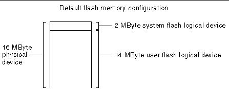

FIGURE 4-3 System Flash and User Flash Logical Devices on Same Physical Device

Figure showing that the logical system flash and user flash devices exist on the same physical device.


4.7 Booting the Board Using the Backup OpenBoot PROM

The main OpenBoot PROM image and a backup copy of the image are stored in the system flash memory (see Section 4.3, System Flash PROM Memory Map). If the OpenBoot PROM becomes corrupted, you can boot the board using the backup copy of the OpenBoot PROM. Booting this backup OpenBoot PROM will enable you to flash update and repair the main OpenBoot PROM image.

To boot the board from a backup image of the OpenBoot PROM in order to update the main OpenBoot PROM image:

1. Power down the board and remove it from the server or chassis.

2. Retrieve the wrist strap from the adapter's shipping kit.

3. Attach the antistatic wrist strap:

a. Attach the adhesive copper strip of the wrist strap to the metal chassis.

b. Wrap the other end twice around your wrist, with the adhesive side against your skin.

4. Place the board on a static-free work area and locate the SW3301 switch on the board.

The SW3301 DIP switch bank is located on the component side of the board between the front panel and heat sink (see FIGURE 4-4).
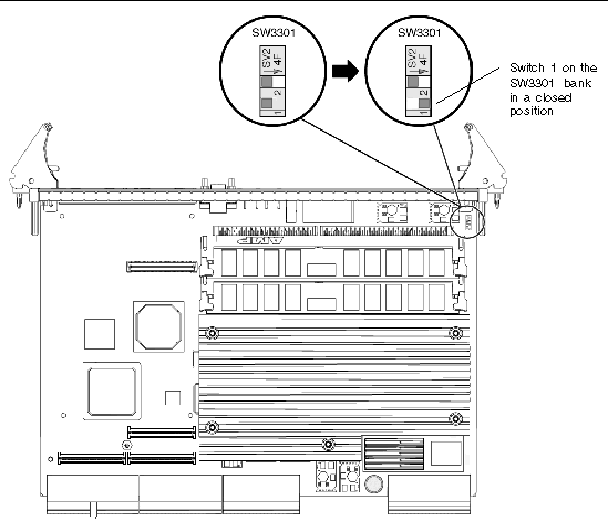

FIGURE 4-4 Setting Switch 1 on the SW3301 DIP Switch Bank to Closed

Figure showing how to close switch 1 of the SW3301 DIP switch bank.


5. Using a needle, metal pick, scribe tool, or small screwdriver, set switch 1 from open to closed.

The closed setting is in the same direction of the arrow located on the SW3301 DIP switch bank (see FIGURE 4-4). For more information about the SW3301 DIP switch settings, see Section B.4, DIP Switch Settings.

6. Install the Netra CP2500 board back in the chassis or server.

Enable the board to boot using the backup OpenBoot PROM and then start the Solaris OS.

7. At a Solaris terminal prompt, update the main OpenBoot PROM firmware.

See Section 2.8.4, Upgrading the OpenBoot PROM and SMC Firmware, for the firmware upgrade procedure.

8. After repairing the main OpenBoot PROM, power down the board and remove it from the chassis or server.

9. Place the board on a static-free work area.

10. Using a needle, metal pick, scribe tool, or small screwdriver, set switch 1 from closed to open.

The open setting is in the reverse direction of the arrow located on the SW3301 DIP switch bank (the open setting is also the default setting).

11. Install the Netra CP2500 board back in the chassis or server.

Enable the board to boot using the main OpenBoot PROM and start the Solaris OS.

4.7.1 Updating the OpenBoot PROM and SMC Firmware

See Section 2.8.4, Upgrading the OpenBoot PROM and SMC Firmware, for the firmware upgrade procedure.


4.8 Firmware Diagnostics

The firmware contains a comprehensive set of hardware diagnostic modules that provide tests for most situations. FIGURE 4-1 shows the control flow relationship of the diagnostic modules with the system firmware. SunVTS can be executed from within the Solaris software if more tests are required. For more information, see Section 3.3, Downloading and Installing SunVTS.

The firmware diagnostic modules are:

The firmware diagnostics cover address and data bits on all system buses and exercise the function of the major hardware resources on the board.

Diagnostics can be performed at OpenBoot PROM level by using the obdiag command, or by typing individual test commands at the ok prompt. These test suites are similar to those in earlier OpenBoot PROM versions but they are comprised of drop-ins that can be placed by the user. Refer to the OpenBoot 4.x Command Reference Manual for additional information.

4.8.1 Setting Diagnostic Levels

The user interface for running POST at minimum or maximum remains the same. POST is executed when the diag-switch? environmental variable is set to true.

4.8.2 OpenBoot PROM On-Board Diagnostics

The OpenBoot PROM on-board diagnostics reside in the OpenBoot PROM drop-in. These diagnostics are described fully in the OpenBoot 4.x Command Reference Manual.

To execute the OpenBoot PROM on-board diagnostics, the system must be at the ok prompt. The OpenBoot PROM on-board diagnostics include:

4.8.3 OpenBoot Diagnostics

The OpenBoot Diagnostics are an enhancement of the traditional system tests. They reside in Forth script in a drop-in and are invoked with an interactive tool that is started from the ok prompt by typing obdiag.

When you start the OpenBoot Diagnostics, you should see the following menu:


ok obdiag
______________________________________________________________________________
|                                 o b d i a g                                |
|_________________________ _________________________ ________________________|
|                         |                         |                        |
|  1 ipmc@0,320           |  2 network@1            |  3 network@1,1         |
|  4 network@3            |  5 network@3,1          |  6 rtc@0,70            |
|  7 serial@0,2e8         |  8 serial@0,3f8         |                        |
|_________________________|_________________________|________________________|
|       Commands: test test-all except help what setenv set-default exit     |
|____________________________________________________________________________|
|                   diag-passes=1 diag-level=max test-args                   |
_____________________________________________________________________________|

At the obdiag prompt, type test 1 to display a printout similar to the following:


obdiag> test 1
 
          Alarmdiag Menu
 
          0 ..... Ethernet Port
          1 ..... Serial Port
          2 ..... Flash
          3 ..... Alarm Port
          4 ..... FRUid Present
          5 ..... FPGA Id
          6 ..... MidPlane Id
          7 ..... Continuity
          8 ..... Slot Leds
          9 ..... Disk Leds
         10 ..... Power Supply Leds
         11 ..... Fan Leds
         12 ..... SCB Leds
         13 ..... FTM Leds              (Netra CT 410 only)
         14 ..... Green Led Blink
         15 ..... FRU Present
         16 ..... Get Health
         17 ..... Power Supply Status
         18 ..... Fan Status
         19 ..... Power Supply Off/On   (Netra CT 810 only)
         20 ..... FruID Checksum
         21 ..... All Above
         22 ..... Quit
         23 ..... Display this Menu
 
Enter (0-21 tests, 22 -Quit, 23 -Menu) ===>