| C H A P T E R 5 |
|
Removing and Replacing Board Hardware |
This chapter describes how to service the field replaceable hardware components of the Netra CP2500 board. This chapter contains the following sections:
|
Note - For instructions on servicing the Netra CP2500 rear transition modules, refer to the Netra CP2500 Rear Transition Module Installation and Technical Reference Manual (819-1753). |
The following field-replaceable units (FRUs) are available from Sun Microsystems:
Contact your field service representative for information about ordering these Netra CP2500 board and RTM FRUs.
Prior to servicing the Netra CP2500 board and its components, review and follow the safety guidelines outlined in Section 2.2, Equipment and Operator Safety.
Also, assemble a set of tools as described in Section 2.3, Materials and Tools Required.

|
Caution - Do not flex the Netra CP2500 board, as the surface-mounted components can break if the board is bent. |
The Sun field-replaceable unit ID (FRU ID) information is stored on a Netra CP2500 board SEEPROM. The FRU ID contains a short description of the board, part numbers, and manufacturing information that can be used to identify the board for service purposes.
To view the board's FRU ID information, use the prtfru command. Refer to the prtfru(1M) man page for further information on this command. The man page can be found on the Solaris documentation web site at:
http://docs.sun.com/
Using the prtfru command at the Solaris command line, you can display the Solaris Sun FRU ID information, which should look similar to the output shown in the following code example. TABLE 5-1 describes the fields shown in the subsequent example.
This section provides a general procedure for removing and replacing a Netra CP2500 board from a cPSB chassis. Refer to your system documentation for board replacement instructions specific to the system and the software application environment.
|
Note - If you are removing and replacing a Netra CP2500 board from a Netra CT 410 or 810 server, refer to replacement procedures in the Netra CT Server Service Manual (819-2741). |
1. Log into the Netra CP2500 board and gracefully stop any applications operating on the board.
Refer to your system's documentation for application procedures specific to your system or chassis.
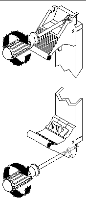
2. On the front of the chassis, and use a No. 1 screwdriver to loosen the ejection lever captive screws securing the board to the chassis.
3. Unlock and press down on the lower ejector lever to start the hot-swap ejection process (see FIGURE 5-2).
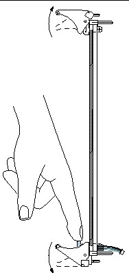
4. Wait until the front panel blue hot-swap LED lights up.
The Netra CP2500 board's hot-swap LED is located in the middle of the board's front panel, and not at the bottom of the panel, as it might be on other boards.
When the blue hot-swap LED lights up, you can safely remove the board from the chassis.

5. If necessary, remove any cable connected to the serial port, or any installed PMC device, from the board (see FIGURE 5-3).
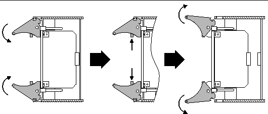
6. Unlock the top ejection lever, and using two hands, simultaneously open the top and bottom ejector levers to disengage the board from chassis backplane (FIGURE 5-4).
7. Take antistatic precautions by attaching and electrically grounding an antistatic wrist strap.
8. Remove the board from the chassis and place the board on an ESD mat (if one is available) on a suitable work area.
If an ESD mat is not available, place the card on the antistatic envelope it was originally packaged in.
9. (Optional) If you will be returning the board to Sun Services, remove the board's SEEPROM and any installed PMC device.
See the following removal procedures:
Follow the installation procedures found in Chapter 2 to install the Netra CP2500 board into a cPSB chassis. Refer to your system documentation for board replacement instructions specific to the system and the software application environment.
The SEEPROM stores the board MAC address and host ID information. You do not need to replace the SEEPROM unless you are installing a replacement board that does not have the host ID information.
1. Remove the board from the chassis and place the board on an ESD mat (if one is available) on a suitable work area.
See Section 5.4.1, Removing the Board From the Chassis for the board removal procedure.
If an ESD mat is not available, place the card on the antistatic envelope it was originally packaged in.
2. Take antistatic precautions by attaching and electrically grounding an antistatic wrist strap.
3. Carefully remove the plastic carrier containing the SEEPROM from the board.
The label is positioned on top of the SEEPROM carrier. See FIGURE 5-5 for the location of the board's SEEPROM carrier.
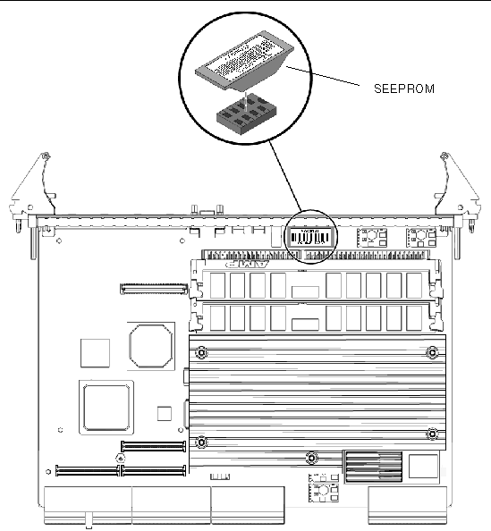
4. Store the removed plastic carrier, which includes the board's SEEPROM, in a safe location.
For the SEEPROM replacement procedure, see Section 2.5.3, Replacing the SEEPROM.
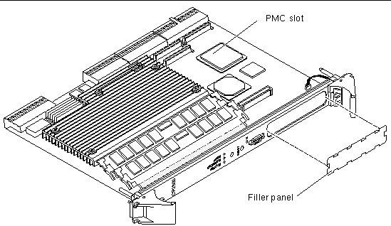
A PCI mezzanine card (PMC) is a slim, modular mezzanine card that provides additional functionality to the Netra CP2500 board. The board contains one PMC slot in which you can an install optional PMC device (see FIGURE 5-8 for the location of the slot).
|
Note - Because an installed PMC device will block access to the memory connector's retainer clips, you need to remove the PMC device prior to removing and replacing the memory modules. |
1. Remove the board from the chassis and place the board on an ESD mat (if one is available) on a suitable work area.
See Section 5.4.1, Removing the Board From the Chassis for the board removal procedure.
If an ESD mat is not available, place the card on the antistatic envelope it was originally packaged in.
2. Take antistatic precautions by attaching and electrically grounding an antistatic wrist strap.
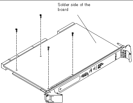
3. Flip the board over on the ESD mat so that the board's solder-side is facing you.
You can only access the screws securing the PMC device from the solder-side of the board.
4. Using a No. 2 screwdriver, remove the four screws securing the PMC device to the board (FIGURE 5-6).
5. Flip the board over on the ESD mat so that the component side of the board is facing you.
6. Carefully lift the PMC device up and off of the board's PMC connectors (see FIGURE 5-7).

7. Lift the PMC device up and off of the board and place the PMC device into an antistatic envelope.
Store the PMC device in a safe location.
8. (Optional) Retrieve and replace the PMC filler panel onto the board's faceplate.
|
Note - To meet EMI compliance standards, your board must contain either an installed PMC device or an installed PMC filler panel. |
9. (Optional) If necessary, remove any installed rear transition module from the rear of the chassis.
Refer to your chassis documentation for the RTM removal procedure.
For the PMC device replacement procedure, see Section 2.5.1, Installing an Optional PMC Device.
The Netra CP2500 board accommodates two 184-pin, very low profile (VLP) DDR-1 SDRAM dual in-line memory modules (DIMMs). The board does not have any on-board memory, so it will not operate without installed memory modules. New Netra CP2500 boards that ship from Sun contain two preinstalled memory modules.

|
Caution - The Netra CP2500 board supports memory modules sold by Sun Microsystems only. Do not install a DIMM pair sold by any other vendor or manufacturer. |
You might need to remove a DIMM module from the Netra CP2500 board if you are returning the DIMM module pair or the board for service, or if you are replacing a DIMM module pair with another DIMM pair purchased from Sun Microsystems.
|
Note - Prior to removing memory modules from the Netra CP2500 board, you will need to remove any installed PMC device. An installed PMC device might block access to the memory connector's retainer clips. For PMC device removal procedures, see Section 5.6.1, Removing a PMC Device. |
|
Note - Safely store the original factory-shipped DIMM and related DIMM packaging. You might want to store any removed DIMM in the new DIMM packaging, or use the packaging for service. |
To remove a DIMM from the Netra CP2500 board, perform the following steps:
1. Remove the board from the chassis and place the board on an ESD mat (if one is available) on a suitable work area.
See Section 5.4.1, Removing the Board From the Chassis, for the board removal procedure.
If an ESD mat is not available, place the card on the antistatic envelope it was originally packaged in.
2. Take antistatic precautions by attaching and electrically grounding an antistatic wrist strap.

|
Caution - Always wear a grounded antistatic wrist strap when handling memory modules. |
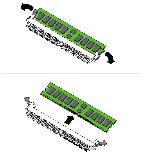
3. For the DIMM you want to remove, simultaneously pull both DIMM retainer clips outward from the slot.
The DIMM releases outward at an angle of about 20 degrees (see FIGURE 5-10).
4. Grasp the DIMM by the edges, and carefully pull it out of its connector (see FIGURE 5-10).
Ensure that you pull the DIMM out at an angle of about 20 degrees, or you might damage the DIMM.
5. Place the DIMM in an antistatic bag.
6. Repeat this procedure for the second DIMM memory module.
|
Note - Prior to installing memory modules on the Netra CP2500 board, you will need to first remove any installed PMC device. An installed PMC device may block access to the memory connector's retainer clips. For PMC device removal procedures, see Section 5.6.1, Removing a PMC Device. |
The following procedure describes how to install memory onto the board.
1. Place the board on an ESD mat (if one is available) on a suitable work area.
If an ESD mat is not available, place the card on the antistatic envelope it was originally packaged in.
2. Take antistatic precautions by attaching and electrically grounding an antistatic wrist strap.

|
Caution - Always wear a grounded antistatic wrist strap when handling memory modules. |
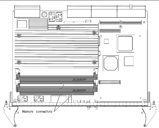
3. Locate the two DIMM connectors on the Netra CP2500 board.
Select the connectors where you will install the memory modules (see FIGURE 5-9). If you need to replace an existing memory module with a new module, see Section 5.7.1, Removing DIMM Memory Modules for instructions on removing the DIMM module.

|
Caution - Do not install just one memory module. You must install memory in matched pairs, with each module containing the same memory capacity. |
4. Carefully pull the memory connector's retainer clips open (see FIGURE 5-11).
5. Remove the DIMM from its protective packaging, holding the module only by the edges.
6. Holding the DIMM at approximately a 20-degree angle to the board, insert the bottom edge of the DIMM into the bottom of the slot connector (see FIGURE 5-11).
The socket and module are both keyed, which means the module can be installed one way only. With even pressure, push simultaneously on both upper corners of the DIMM until its bottom edge (the edge with the gold fingers) is firmly seated in the connector.
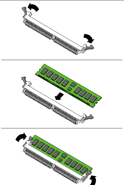
7. Press the top edge of the DIMM toward the board until the retainer clips click into place (see FIGURE 5-11).
The small retainer clips on each side of the DIMM slot click into place in the notches on the DIMM sides.
8. Repeat this procedure for the second DIMM memory module.
|
Note - If you removed a PMC device prior to removing and replacing memory modules, see Section 2.5.1, Installing an Optional PMC Device for the PMC device replacement procedure. |
Copyright © 2007, Sun Microsystems, Inc. All Rights Reserved.