| Netra CP2500 Board Installation and Technical Reference Manual
|
   
|
Specifications for the Netra CP2500 board are provided in the following sections:
A.1 System Compatibility Specifications
The Netra CP2500 board is fully compatible with the Netra CT 410/810 servers. TABLE A-1 lists the attributes of a compatible cPSB chassis.
TABLE A-1 cPSB Chassis Compatibility Attributes
|
Property
|
Specification
|
|
H110 chassis compatible
|
CompactPCI J4 is unconnected at the board, which enables this board to be used in an H110 chassis
|
|
NEBS
|
NEBS Level 3 compliant chassis
|
|
I/O Voltage
|
Backplane power input (VIO) must be 5V.
|
|
CompactPCI compatibility
|
- PICMG 2.16 CompactPCI Packet Switched Backplane specification
- PICMG 2.1 R1.0 Hot-Swap specification
- PICMG 2.9 System Management specification
|

|
Caution - The backplane power input (VIO) mustbe 5V. Otherwise, the board and the chassis can become seriously damaged.
|
A.2 CPU Specifications
TABLE A-1 CPU Specifications
|
Property
|
Specification
|
|
CPU
|
UltraSPARC IIIi
|
|
Architecture
|
Sun 4U; 64-bit SPARC V9 architecture with the VIS instruction set
|
|
Cache
|
Integrated, 4 Mbyte, 4-way, set-associative internal L2 cache
|
|
PCI bus local interface
|
PCI Bus 2.1 compatible, 33 MHz, 32-bit, 3.3V (internal to board only)
|
A.3 PMC Interface Specifications
TABLE A-2 PMC Interface Specification
|
Property
|
Specification
|
|
PMC module interface on system board
|
One PMC interface
|
|
Interface IEEE P1386.1 compliance
|
With draft 2.1
|
|
Connector configuration, PMC A (P1386 designations)
|
Jn1, Jn2 carry PCI signals; Jn4 module I/O is connected to the CompactPCI J5 backplane connector
|
|
PCI clock
|
33 MHz
|
|
PCI bus width
|
32-bit
|
|
Max power load - per module, combined power rails (5V, 3.3V,
12V, -12V)
|
7.5 W (5V keyed or universal)
|
A.4 Power Requirements
This section provides information on power sequencing and power requirements by connection phase. TABLE A-3 shows the power drawn from the backplane connector by phase.
TABLE A-3 Netra CP2500 Backplane Connector Power Requirements by Connection Phase
|
Power Rail
|
No backplane power
|
Main power on medium pins
(Typical configuration with two 1GB DIMMs installed)
|
Description
|
|
+5V
|
0
|
9 A
|
At CompactPCI connectors J1/J2
|
|
+3.3V
|
0
|
3 A
|
At CompactPCI connectors J1/J2
|
|
+12V
|
0
|
0.5 A
|
At CompactPCI connectors J1/J2
|
|
-12V
|
0
|
0
|
At CompactPCI connectors J1/J2
|
|
IPMB_PWR
|
0.25
|
0
|
At CompactPCI connector J1/A4
|
A.5 Mechanical Specifications
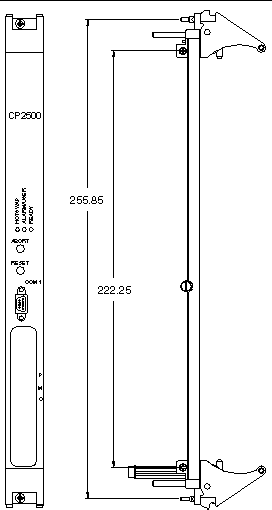
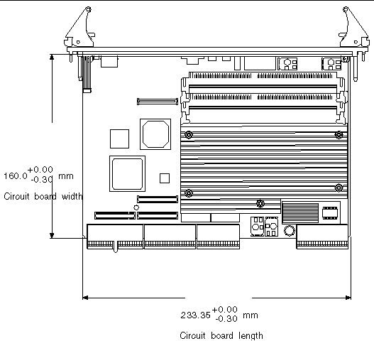
The Netra CP2500 board meets the mechanical specifications found in the CompactPCI specification PICMG 2.0 R3.0. FIGURE A-1 shows mechanical dimensions of the Netra CP2500 board panel, and FIGURE A-2 shows the mechanical dimensions of the board itself.
FIGURE A-1 Physical Dimensions of the Netra CP2500 Front Panel

FIGURE A-2 Mechanical Dimensions of the Netra CP2500 Board

A.6 Environmental Specifications
TABLE A-4 Environmental Conditions and Limits
|
Ambient Conditions
|
Low Limit
|
High Limit
|
|
Transportation and storage temperature
|
-400 C
|
+700 C
|
|
Transportation and storage humidity
|
5% RH
noncondensing
|
95% RH
noncondensing
|
|
Operating temperature
|
00 C (-50 C short term)
|
400 C (550 C short term)
|
|
Operating humidity
|
15% RH
noncondensing
|
85% RH (90% RH short term)
noncondensing
|
|
Shock and vibration
|
NEBS GR-63 CORE - Sections 4.3.1 and 4.3.2 for shock criteria and Section 4.4.3 for vibration criteria
|
|
Electrostatic discharge
|
NEBS GR-1089 - Section 2
|
A.7 Cooling Requirements
The CPU diode temperature should not exceed 1050 C when installed in the system. Refer to the Netra CP2500 Board Programming Guide (819-1749) for more information on thermal validation.
A.8 Reliability and Availability Specifications
Reliability, availability, and serviceability (RAS) specifications for the Netra CP2500 board are available through the Sun sales office under a nondisclosure agreement.


