Disk Drives
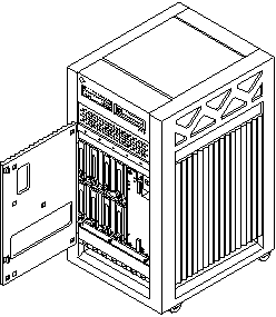
Disk drive banks are located in the front of the Enterprise 3500 system. A system supports up to eight single connector 3.5 inch hard disk drives of the 1.0 inch form factor, or eight drives of the 1.6 inch form factor. Disk drives with different form factors may be mixed within a single system.
All disk drives use fiber optic interface and connect by way of the centerplane connectors to an interface board (IB) that can be installed in the system rear, next to the peripheral power supply/AC. For information about the IB and GBICs (Gigabit interface converters), see Chapter 6, Interface Board.
Note -
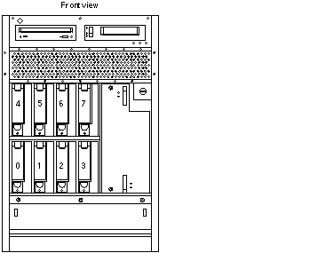
Reserve drive bay 0 for the boot disk (see Figure 8-5).
Use and Maintenance
Refer to the documentation that came with your disk drive for instructions on use and maintenance.
Removing a Disk Drive
Prior to performing the following procedure, ensure that you perform any necessary software tasks. Failure to perform any necessary software tasks prior to removing or replacing a disk drive may result in loss of data.
Note -
Disk drives used in Enterprise 3500 systems have a retainer mechanism that doubles as an extraction handle.
-
Open the system front door. See Figure 8-4.
Figure 8-4 Disk Drive Access

-
Locate the drive to be replaced. See Figure 8-5.
 Caution -
 You must wear a wrist strap when handling disk drives to prevent damage to the system components.
Figure 8-5 Disk Drive Bays

Note -The disk drive retainer must be unlatched and then extended 45 degrees, to an unlocked position, for a drive to be removed or replaced in the system chassis.
 Caution -
 Do not tug with abrupt force on the retainer; doing so can cause it to break off.
-
To remove the drive:
-
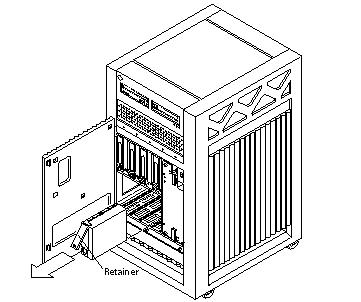
Unlatch the drive retainer and extend it 45 degrees. Use the extended, unlocked retainer as a handle. See Figure 8-6.
Figure 8-6 Disk Drive with Retainer Unlatched and Extended

-
Gently but firmly pull on the handle to slide the drive out of the chassis.
Once the drive is partially removed from the mounting rails, grasp the bottom of the drive to aid in removal.
-
-
If the drive is to be replaced, proceed to "Installing a Disk Drive".
Installing a Disk Drive
-
Attach a grounding wrist strap.
Refer to the documentation that came with your ESD kit.
 Caution -
 You must wear a wrist strap when handling disk drives to prevent damage to the system components.
-
Remove the disk drive from its protective packaging and place it on an ESD mat.
Note -The drive retainer must be unlatched and extended 45 degrees, to an unlocked position, in order for the drive to be inserted into the system chassis guide rails.
-
Unlatch and then extend the drive retainer to the unlocked position.
Use the extended retainer as a handle to gently guide the drive so that the plastic rails on the top and bottom of the drive slide in to the drive mounting rails in the system chassis.
-
Once the connector on the rear of the drive is positioned against the centerplane connector, gently compress the face of the drive and snap the connectors together.
The drive and centerplane connectors make a "clicking" sound as they come together.
Note -Disk drive IDs are automatically selected when a drive is placed in a disk drive bay. The disk drive ID for the corresponding bay is marked on the system chassis.
-
Latch the drive retainer into place.
Check that the retainer on the disk drive is latched into place when closed, and does not extend past the edge of the chassis.
If the retainer extends past the edge of the chassis or will not fully latch, the disk drive connector is not joined with the centerplane connector. Do the following:
-
Unlatch the drive retainer and extend it to the unlocked position.
-
Do not remove the drive; instead, use the retainer as a handle to slide it out an inch or two.
-
Check that the connectors are not broken and that nothing blocks the joining of the two connectors.
Put the disk drive back into its protective packaging and contact your service representative if there is still a problem.
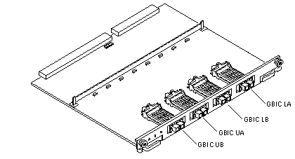
Note -If you are installing the disk in a previously unused disk drive bank and the system does not recognize the disk, the GBIC interface for that bank may be missing or located in the wrong port on the IB. See Table 8-1 and Figure 8-7.
Table 8-1 GBIC Controllers for Disk Drive PortsDisk Drives
Drive Port
GBIC Name and Drive Location
0, 1, 2, 3
A
GBIC LA (Lower bank)
0, 1, 2, 3
B
GBIC LB (Lower bank)
4, 5, 6, 7
A
GBIC UA (Upper bank)
4, 5, 6, 7
B
GBIC UB (Upper bank)
Figure 8-7 Interface Board GBIC Ports

-
- © 2010, Oracle Corporation and/or its affiliates
