| C H A P T E R 6 |
|
Removing and Replacing Hot-Swappable Cards |

|
Caution - If you are just powering on your Netra CT server, do not remove or install any cards in the system until you have verified that the system is completely powered up. Refer to Section 2.1.1, Verifying Full Power-Up for more information. |

|
Caution - An energy hazard is present if any I/O slots are left uncovered. If you remove a card from an I/O slot, you must fill it with either a replacement card or a filler panel. |
|
Note - Consult the Netra CT Server Safety and Compliance Manual and Chapter 3 of this document for safety and board-handling information prior before performing the procedures in this chapter. |
There are three types of cards that are hot-swappable in the Netra CT server:
The procedures for removing and replacing these cards are given in Section 6.1, Main Cards.
Note that the front transition cards are only hot-swappable as long as the accompanying host CPU card has been removed first.
The procedures for removing and replacing these cards are given in Section 6.2, Front-Transition Card.
Note that the rear transition cards are only hot-swappable as long as the accompanying main card has been removed first.
The procedures for removing and replacing these cards are given in Section 6.3, Rear-Transition Cards.
This section gives procedures for the installation, removal, and replacement of the following hot-swappable cards for the front-access models of the Netra CT 410 server and Netra CT 810 server:
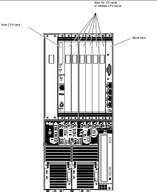
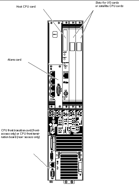
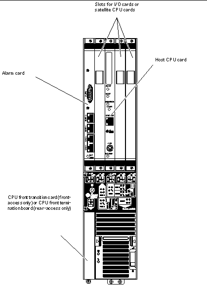
FIGURE 6-1 shows the locations of these cards in the Netra CT 810 server. FIGURE 6-2 shows the locations of these cards in the diskfull Netra CT 410 server, and FIGURE 6-3 shows the locations of these cards in the diskless Netra CT 410 server.
Before removing and replacing any of the main cards in your server, you must first understand all rules and restrictions involved. The following sections describe the rules and restrictions for the main cards:
Following are the rules and restrictions you must understand before hot-swapping any card in the Netra CT server:
1. You must have the host CPU card, alarm card and system controller board installed in the Netra CT server before you can hot-swap any I/O card or satellite CPU card.
2. You may not be able to perform a full hot-swap on any card if the card is in a failed condition; you must perform a basic hot-swap in this case. To determine if a card has failed, verify that these LEDs are in following states:
If the card has failed, you must manually unconfigure the card before you can hot-swap it by entering the following commands:
where ap_id is the attachment-point ID listed in the first column.
If the LED states continue to show a failed condition for the card, then you must halt the system.
3. You can only remove a card if all of these LEDs are in the following states:
Do not remove any card from the system if any of the LEDs is not in the proper state.
Following are the rules and restrictions you must understand before hot-swapping a host CPU card:
1. You must have the alarm card and system controller board installed in the Netra CT server before you can hot-swap the host CPU card.
2. When you remove a host CPU card from a server while the server is running, it will disable the CompactPCI bus, which means that the connection with all I/O cards installed in the server will be lost. Once the CompactPCI bus is disabled, MCNet will also become disabled in the system.
After you install the host CPU card back into the server, it will enable the CompactPCI bus and will attempt to connect to all occupied card slots.
Satellite CPU cards are unaffected by the disabling of the CompactPCI bus; they will continue to function as stand-alone processors when you hot-swap a host CPU card.
3. If the host CPU is at the OpenBoot prompt (the ok prompt) and you want to hot-swap the host CPU card, you must power off the host CPU slot through the alarm card.
To power off the host CPU slot in a Netra CT server, access the alarm card and, through the alarm card command line interface, enter:
Refer to the Netra CT Server System Administration Manual for more information on accessing the alarm card.
Use the poweron command to power on the host CPU card once you've installed the replacement host CPU card.
4. If you are installing a Netra CP2140 host CPU board into a Netra CT server, do not change the default SMC module switch settings on the SW0501 switches. The Netra CT server supports high availability hot swap; however, because the alarm card controls the high availability on the Netra CT server, the settings on the SW0501 switches on the Netra CP2140 host CPU card should actually be set in the default, non-high availability settings. Refer to the Netra CT Server Product Overview for more information.
Following are the rules and restrictions you must understand before hot-swapping an alarm card:
1. You must have the host CPU card and the system controller board installed in the Netra CT server before you can hot-swap the alarm card.
2. You cannot hot-swap any other component in a Netra CT server while the alarm card is being hot-swapped.
3. You cannot install any new component into a Netra CT server while the alarm card is being hot-swapped.
The individual slots in your server will be set to full hot swap by default. You can also change the slots to basic hot swap manually. Refer to Chapter 5 for more information.
|
Note - Do not proceed with these instructions until you have reviewed the information in Section 6.1.1, Rules and Restrictions for Hot-Swapping Main Cards. Failure to do so may result in an inadvertent system reboot or incorrect configuration information. |
1. Locate the card that you want to remove from the server.
FIGURE 6-1 shows the locations of these cards in the Netra CT 810 server. FIGURE 6-2 shows the locations of these cards in the diskfull Netra CT 410 server, and FIGURE 6-3 shows the locations of these cards in the diskless Netra CT 410 server.
2. Log into the Netra CT server.
Refer to Section 5.2.1, Logging In to the Netra CT Server, then return to this procedure.
3. Perform any necessary card-specific software commands.
4. Determine the hot swap state for the slot that holds the card you are about to remove.
To determine the current hot swap state for the slots in your server, as root, enter:
The output is similar to the following (note that the following output is for a Netra CT 810 server; the output is similar for the Netra CT 410 server):
5. Identify the attachment-point ID that corresponds to the slot where you will be removing the card.
For a Netra CT 810 server, you should get feedback similar to the following:
For a Netra CT 410 server, you should get feedback similar to the following:
The attachment-point ID is shown in the first column of the readout; for example, the attachment-point ID for slot 4 in a Netra CT 810 server would be IO-4.
6. Disconnect the card with the cfgadm (1m) utility:
where ap_id is the attachment-point ID. For example, to deactivate the card in slot 4, as root, enter:
7. If you are hot-swapping an alarm card, reset the alarm card before removing it.
Refer to the Netra CT Server System Administration Manual for more information.
8. Attach the antistatic wrist strap.
Refer to Section 1.2, Attaching the Antistatic Wrist Strap.
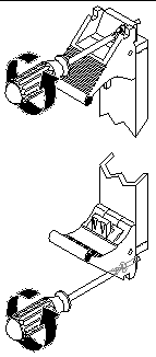
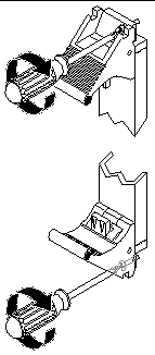
9. Using a No. 2 Phillips screwdriver, loosen the two captive screws inside the card's ejection levers, one on top and one on the bottom (FIGURE 6-4).
10. Unlock the ejection levers.

|
Caution - Only unlock the ejection levers at this point; do not unseat the card until the LEDs on the system status panel are in the proper state. |
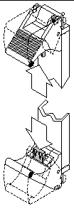
There are several different models of locking ejection levers, so the method you would use to unlock the ejection levers will vary depending on the model of the ejection lever used on the card; for example, one model uses red tabs at the top and bottom to unlock the card (FIGURE 6-5). Refer to the documentation that came with the card for instructions on unlocking the card.
11. Locate the LEDs on the system status panel for the card that you want to remove.
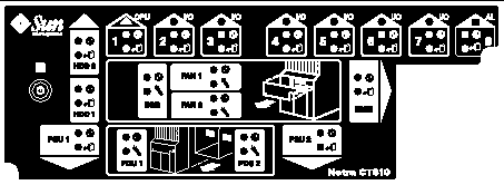
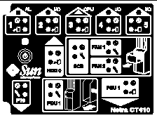
The system status panel on each server has LEDs that show the status of the card installed in each set of the slots in that particular server. FIGURE 6-6 shows the LEDs on the Netra CT 810 server and FIGURE 6-7 shows the LEDs on the Netra CT 410 server.
12. Determine if you can remove the card safely at this time.
You can remove the card only if all of these LEDs are in the following states:
For more information on all the stages and meanings of the system status panel LEDs, refer to Troubleshooting the System Using the System Status Panel. The following table gives more detailed information on the LEDs and the meanings of each of their states.
|
Note - If the server is set to the default full hot-swap mode, unlocking the ejection levers automatically starts the cfgadm unconfigure operation. If you decide that you do not want to remove the card, you must wait until the LEDs are in the correct state (as shown in Step 12), completely unseat the card, reseat it, then lock the ejection levers again in order to start the cfgadm configure operation. Simply locking the ejection levers after unlocking them will not start the driver attachment process. |
13. When it is safe to remove the card, disconnect any cables connected to the card.
14. Press outward on the two ejection levers on the card to unseat the card from the card cage.
15. Carefully slide the card out of the slot and place it on the electrostatic discharge mat.
If you are hot-swapping an alarm card, you may notice one thing that is unique to the alarm card. If you enter the cfgadm command after you have removed the alarm card, you will see disconnected under the Receptacle column. For all other cards, after you have removed the card, you should see empty under the Receptacle column.
16. Perform any additional card-specific hardware procedures, if necessary.
For example, you may want to remove the PMC(s) from a faulty satellite CPU or I/O card and install it on the replacement card later on. Refer to the documentation that you received with your card for more information.
17. Secure a blank filler panel over the empty I/O slots, if necessary.
If you are not going to replace the card right away, you must install a blank filler panel over the opening to ensure proper airflow in the system. The slot filler panel is secured to the card cage using two screws, one at the top of the filler panel, the other at the bottom.
18. Determine if you are removing a card from a front-access or rear-access model server.
1. Attach the antistatic wrist strap.
Refer to Section 1.2, Attaching the Antistatic Wrist Strap.
2. Locate the card slot where you will be installing the card.
FIGURE 6-1 shows the locations of these cards in the Netra CT 810 server. FIGURE 6-2 shows the locations of these cards in the diskfull Netra CT 410 server, and FIGURE 6-3 shows the locations of these cards in the diskless Netra CT 410 server.
3. Determine if you are installing a card in the front-access model or the rear-access model of the Netra CT server.
4. Remove the slot filler panel, if necessary.
The slot filler panel is secured to the card cage using two screws, one at the top of the filler panel, the other at the bottom. Store the slot filler panel in a safe place; you may have to use it again if you have to remove a card for an extended period of time.
5. Get the replacement card from the ship kit.
6. If you are installing a new alarm card, remove the blue protective film from the front of the alarm card, if necessary.
7. Perform any card-specific hardware procedures, if necessary.
For example, if you removed a PMC from a satellite CPU or I/O card, then you will want to install the PMC into the replacement satellite CPU or I/O card at this time. Refer to the documentation that you received with your satellite CPU or I/O card for more information.
8. Verify that the ejection levers on the card are unlocked.
You will not be able to install the card properly if the ejection levers are locked.
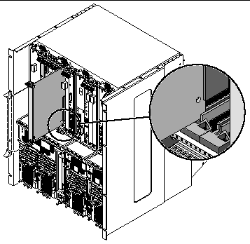
9. Keeping the card vertical, slide the card into the slot between the two guides.
The cuts in the handle of the card must align with the square cutouts in the slot. When the card is completely seated in the card cage, the two ejection levers should flip inward, and the notches in the ejection levers should fit smoothly in the rectangular cutouts in the bottom and top plates.
There are several different models of locking ejection levers, so the method you would use to lock the ejection levers will vary depending on the model of the ejection lever used on the card. Refer to the documentation that came with the card for instructions on locking the ejection levers.
11. Using a No. 2 Phillips screwdriver, tighten the two captive screws inside the card's ejection levers, one on top and one on the bottom.
Tighten the screws to a torque of 0.28 N.m (2.5 in.-lb).
12. Log into the Netra CT server.
Refer to Section 5.2.1, Logging In to the Netra CT Server, then return to this procedure.
13. Determine the hot swap state for the slot that holds the card you just installed.
To determine the current hot swap state for the slots in your server, as root, enter:
The output is similar to the following (note that the following output is for a Netra CT 810 server; the output is similar for the Netra CT 410 server):
14. Identify the attachment-point ID that corresponds to the slot where you inserted the card.
For a Netra CT 810 server, you should get feedback similar to the following:
For a Netra CT 410 server, you should get feedback similar to the following:
The attachment-point ID is shown in the first column of the readout; for example, the attachment-point ID for slot 4 in a Netra CT 810 server would be IO-4. Note that the information for the card installed in slot 4 in the example feedback shows it as unknown (Type), disconnected (Receptacle), unconfigured (Occupant), and unknown (Condition). This confirms that the slot has been set to basic hot swap and that the card in the slot has not yet been activated.
15. Connect the card with the cfgadm dynamic reconfiguration software:
where ap_id is the attachment-point ID. For example, to connect the card in slot 4, as root, enter:
16. Activate the card with the cfgadm (1m) utility:
where ap_id is the attachment-point ID. For example, to activate the card in slot 4, as root, enter:
If you were to enter the cfgadm pci command again at this point, you should see the fields changed for the card in slot 4:
17. Locate the LEDs on the system status panel for the card that you just inserted.
FIGURE 6-6 shows the LEDs on the Netra CT 810 server and FIGURE 6-7 shows the LEDs on the Netra CT 410 server.
18. Determine if the card has been activated.
Refer to TABLE 6-2 to determine if the card has been activated.
19. If the card has come up successfully, perform any card-specific software configuration procedures, if necessary.
20. Connect the cables to the card.
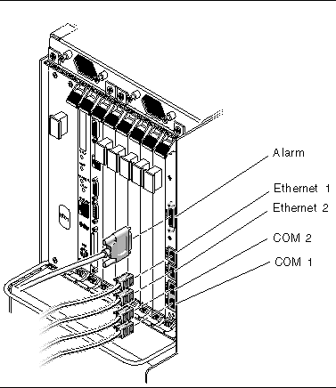
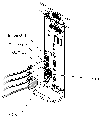
Tighten the screws on the cable to a torque of 0.23 N.m (2 in.-lb).
The following figures show the connectors for the cards available for the Netra CT servers:
For the connectors on the satellite CPU and I/O cards, refer to the documentation that you received with those cards.
Refer to Appendix A for connector pinouts for each card, if necessary.
|
Note - The host CPU front-transition cards are only hot-swappable as long as the host CPU card has been removed first. |
If you encounter problems with the host CPU and/or the host CPU front transition card, you may not be able to determine which card of the two is causing the problems. Because of that, you might want to replace both cards when one of them fails.
1. Attach the antistatic wrist strap.
Refer to Section 1.2, Attaching the Antistatic Wrist Strap.
2. Go to the front of the system and remove the host CPU card, if you have not done so already.
Refer to Section 6.1.2.1, Removing a Main Card to remove the host CPU card, then return here.
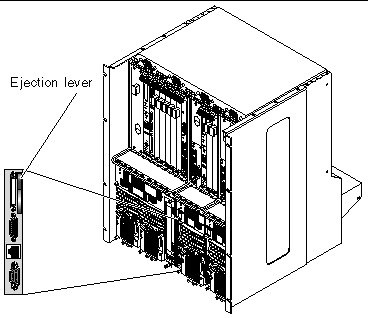
3. Locate the host CPU front transition card.
FIGURE 6-13 shows the location of the host CPU front transition card in a Netra CT 410 server.
4. Disconnect any cables attached to the host CPU front transition card.
5. Using a No. 2 Phillips screwdriver, loosen the captive screw inside the card's ejection lever.
6. Flip up on the ejector lever to unseat the card from the card cage (FIGURE 6-13).
7. Slide the card out of the slot and place it on the electrostatic discharge mat.
1. Attach the antistatic wrist strap.
Refer to Section 1.2, Attaching the Antistatic Wrist Strap.
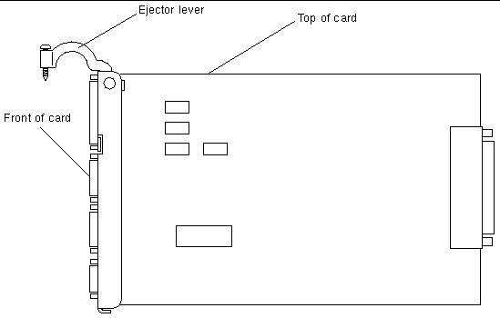
2. Flip the ejector lever up to a 90-degree angle (FIGURE 6-14).
3. Keeping the card vertical, slide the card into the slot.
4. Press down on the ejector lever to seat the card into the card cage (FIGURE 6-13).
5. Using a No. 2 Phillips screwdriver, tighten the captive screw inside the card's ejection lever.
Tighten the screw to a torque of 0.28 N.m (2.5 in.-lb).
6. Make the necessary cable connections to the host CPU front transition card.
Tighten the screws on the cable to a torque of 0.23 N.m (2 in.-lb).
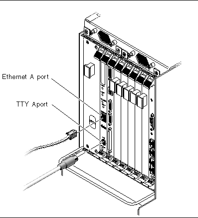
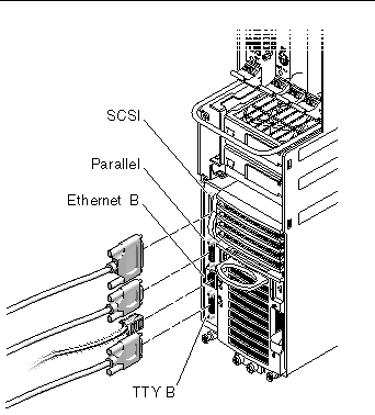
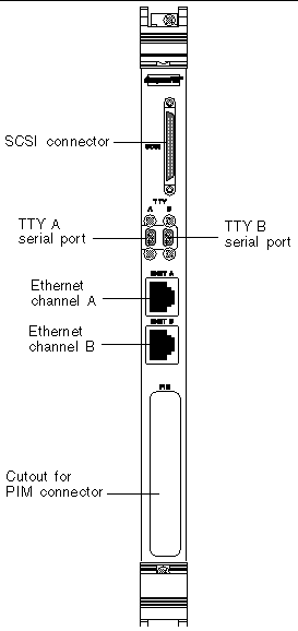
FIGURE 6-15 shows the connectors on the host CPU front transition card for the Netra CT 410 server. Note that the TTY A port is located on the host CPU card itself (COM port) for the Netra CT 410 server.
7. After you have replaced the host CPU front transition card, get the replacement host CPU card from the ship kit.
8. Go to the front of the server and install the host CPU card.
Refer to Section 6.1.2.2, Inserting a Main Card for those instructions.
|
Note - The rear-transition cards are only hot-swappable as long as the accompanying main card has been removed first. |
This section gives procedures for the installation, removal, and replacement of the following hot-swappable cards for rear-access models of the Netra CT 410 server and Netra CT 810 server:
This section tells how to remove and replace a host CPU rear transition card. This card is present only in the rear-access model of the Netra CT server.
|
Note - The procedures in this section apply only to the rear-access model of the Netra CT server; the procedures in this section do not apply to a front-access model of the Netra CT server. |
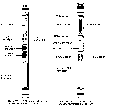
Use only the Netra CT-supported host CPU rear transition card in the Netra CT server; do not use the XCP2040-TRN I/O transition card that is available with the Netra CP2140 board. Refer to FIGURE 6-16 to determine if the host CPU rear transition card you have is supported or unsupported on a Netra CT server.
1. Attach the antistatic wrist strap.
Refer to Section 1.2, Attaching the Antistatic Wrist Strap.
2. Go to the front of the system and remove the host CPU card, if you have not done so already.
Refer to Section 6.1.2.1, Removing a Main Card to remove the host CPU card, then return here.
3. Go to the rear of the system and locate the host CPU rear transition card.
FIGURE 6-17 shows the location of the host CPU rear transition card on the Netra CT 810 server, and FIGURE 6-18 shows the location of the host CPU rear transition card on the Netra CT 410 server.
4. Unplug any cables attached to the host CPU rear transition card.
5. Using a No. 2 Phillips screwdriver, loosen the two captive screws inside the card's ejection levers, one on top and one on the bottom (FIGURE 6-4).
6. Press out on the ejection levers to unseat the card.
7. Slide the card out of the slot and place it on the electrostatic discharge mat.
1. Attach the antistatic wrist strap.
Refer to Section 1.2, Attaching the Antistatic Wrist Strap.
2. Get the replacement host CPU rear transition card from the ship kit.
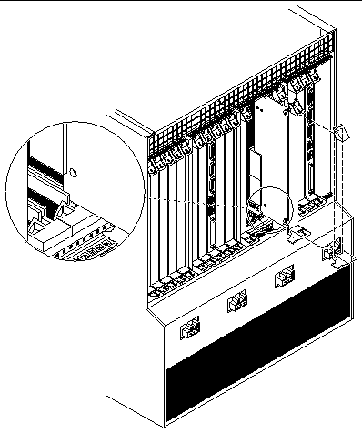
3. Keeping the host CPU rear transition card vertical, slide the card into the slot in between the two guides (FIGURE 6-19).
The teeth in the handle of the card must align with the square cutouts in the slot. When the card is completely seated in the card cage, the two ejection levers should flip inward, and the teeth in the ejection levers should fit smoothly in the rectangular cutouts in the bottom and top plates. FIGURE 6-19 shows how to insert an I/O card into a slot; the same principal applies to a host CPU rear transition card.
4. Using a No. 2 Phillips screwdriver, tighten the two captive screws inside the card's ejection levers, one on top and one on the bottom (FIGURE 6-9).
Tighten the screws to a torque of 0.28 N.m (2.5 in.-lb).
5. Make the necessary cable connections to the host CPU rear transition card.
Tighten the screws on the cable to a torque of 0.23 N.m (2 in.-lb).
FIGURE 6-20 shows the connectors on the host CPU rear transition card.
6. After you have replaced the host CPU rear transition card, get the replacement host CPU card from the ship kit.
7. Go to the front of the server and install the replacement host CPU card.
Refer to Section 6.1.2.2, Inserting a Main Card for those instructions.
The satellite CPU rear transition card set consists of two separate cards:
The satellite CPU card is installed from the front of the Netra CT server; however, no cables are connected to the satellite CPU card. It is the same satellite CPU card that is used in the front-access model of the Netra CT server.
The rear transition card extends the ports from the PMCs installed in the satellite CPU card to the PIMs installed in the satellite CPU rear transition card. The satellite CPU card must be installed in the same slot at the front of the server in order for the satellite CPU rear transition card to work. For example, if you install a satellite CPU rear transition card in I/O slot 3 at the rear of a Netra CT 810 server, you must also install the accompanying satellite CPU card in I/O slot 3 at the front of the server.
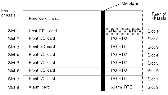
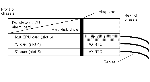
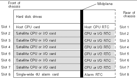
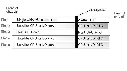
When one of the two cards fails, you may not be able to determine which of the two cards has failed. Because of this, you may want to replace both the satellite CPU card and the satellite CPU rear transition card. FIGURE 6-21 and FIGURE 6-22 give graphical representations of how the satellite CPU cards should align with the satellite CPU rear transition cards (RTCs). Note that, if you are facing the front of the server, the I/O slots read from left to right, whereas they read from right to left if you are facing the rear of the server.
The I/O rear transition card set consists of two separate cards:
The front I/O card contains the ASICs for the associated I/O card and is installed from the front of the server; however, no cables are connected to the front I/O card.
The I/O rear transition card extends the ports for a particular I/O card to the rear of the server. The I/O rear transition card and the front I/O card must be installed in the same slot at the front of the server in order for the I/O rear transition card to work. For example, if you install an I/O rear transition card in I/O slot 3 at the rear of a Netra CT 810 server, you must also install the accompanying front I/O card in I/O slot 3 at the front of the server.
When one of the two cards fails, you may not be able to determine which of the two cards has failed. Because of this, you may want to replace both the front I/O card and the I/O rear transition card. FIGURE 6-21 and FIGURE 6-22 give graphical representations of how the front I/O cards should align with the I/O rear transition cards (RTCs). Note that, if you are facing the front of the server, the I/O slots read from left to right, whereas they read from right to left if you are facing the rear of the server.
1. Attach the antistatic wrist strap.
Refer to Section 1.2, Attaching the Antistatic Wrist Strap.
2. Locate the card slot that holds the satellite CPU or I/O card.
3. Remove the satellite CPU or I/O card from the front of the Netra CT server.
Refer to Section 6.1.2.1, Removing a Main Card for those instructions, then return here.
4. After you have removed the satellite CPU or I/O card from the front of the Netra CT server, go to the rear of the server and locate the rear transition card.
FIGURE 6-21 shows the slots available for the rear transition cards in a Netra CT 810 server and FIGURE 6-22 shows the slots available for the rear transition cards in a Netra CT 410 server.
5. Unplug any cables attached to the rear transition card, if necessary.
6. Using a No. 2 Phillips screwdriver, loosen the two captive screws inside the rear transition card's ejection levers, one on top and one on the bottom (FIGURE 6-4).
7. Unlock the ejection levers.
8. Press outward on the two ejection levers on the card to unseat the card from the card cage.
9. Carefully slide the rear transition card out of the slot and place it on the electrostatic discharge mat.
10. Perform any additional card-specific hardware procedures, if necessary.
For example, you may want to remove the PIM(s) from a faulty satellite CPU or I/O card and install it on the replacement card later on. Refer to the documentation that you received with your card for more information.
11. Secure blank filler panels over the empty I/O slots, if necessary.
If you are not going to replace the cards right away, you must install blank filler panels over the openings to ensure proper airflow in the system. The slot filler panels are secured to the card cage using two screws, one at the top of the filler panel, the other at the bottom.
1. Attach the antistatic wrist strap.
Refer to Section 1.2, Attaching the Antistatic Wrist Strap.
2. Remove the slot filler panel, if necessary.
FIGURE 6-21 shows the slots available for the rear transition cards in a Netra CT 810 server and FIGURE 6-22 shows the slots available for the rear transition cards in a Netra CT 410 server.
The slot filler panel is secured to the card cage using two screws, one at the top of the filler panel, the other at the bottom.
3. Get the replacement rear transition card from the ship kit.
4. Perform any card-specific hardware procedures, if necessary.
For example, if you removed the PIM(s) from a faulty satellite CPU or I/O card, then you will want to install the PIM(s) into the replacement satellite CPU or I/O card at this time. Refer to the documentation that you received with your satellite CPU or I/O card for more information.
5. Verify that the ejection levers are unlocked.
You will not be able to install the card properly if the ejection levers are locked.
6. Keeping the card vertical, slide the rear transition card in between the two guides into the slot (FIGURE 6-19).
The teeth in the handle of the card must align with the square cutouts in the I/O slot. When the card is completely seated in the card cage, the two ejection levers should flip inward, and the teeth in the ejection levers should fit smoothly in the rectangular cutouts in the bottom and top plates.
The method you use to lock the ejection levers varies depending on the model of the ejection lever used on the card. Refer to the documentation that came with the I/O card for instructions on locking the ejection levers.
8. Using a No. 2 Phillips screwdriver, tighten the two captive screws inside the card's ejection levers, one on top and one on the bottom.
Tighten the screws to a torque of 0.28 N.m (2.5 in.-lb).
9. Plug all appropriate cables into the rear transition card.
Tighten the screws on the cable to a torque of 0.23 N.m (2 in.-lb). Refer to the documentation that you received with the card for more information.
10. Go to the front of the server and install the satellite CPU or I/O card in the Netra CT server.
Refer to Section 6.1.2.2, Inserting a Main Card for those instructions.
The alarm rear transition card for the Netra CT 810 server consists of two separate cards:
When one of the two cards fails, you may not be able to determine which of the two cards has failed. Because of this, you may want to replace both the alarm card and the alarm rear transition card.
The alarm card is installed from the front of the Netra CT server. It is the same alarm card that is used in the front-access model of the Netra CT server.
The alarm rear transition card extends the ports on the alarm card installed at the front of the server to the alarm rear transition card installed at the rear of the server. The alarm card must be installed in the front of the server in order for the alarm rear transition card to work.
1. Attach the antistatic wrist strap.
Refer to Section 1.2, Attaching the Antistatic Wrist Strap.
2. Remove the alarm card from the front of the Netra CT server.
Refer to Removing a Main Card for those instructions, then return here.
3. After you have removed the alarm card from the front of the Netra CT server, go to the rear of the server and locate the alarm rear transition card.
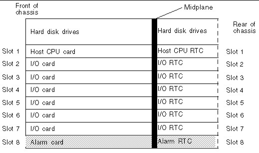
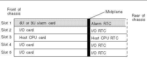
FIGURE 6-23 shows the slot available for the alarm rear transition card in a Netra CT 810 server and FIGURE 6-24 shows the slot available for the alarm rear transition card in a Netra CT 410 server.
4. Unplug any cables attached to the alarm rear transition card, if necessary.
5. Using a No. 2 Phillips screwdriver, loosen the two captive screws inside the card's ejection levers, one on top and one on the bottom.
6. Unlock the ejection levers on the card.
7. Press outward on the two ejection levers on the card to unseat the card from the card cage.
8. Slide the card out of the slot and place it on the electrostatic discharge mat.
9. Secure blank filler panels over the empty I/O slot, if necessary.
If you are not going to replace the alarm card and alarm rear transition card right away, you must install blank filler panels over the openings to ensure proper airflow in the system. The slot filler panels are secured to the card cage using two screws, one at the top of the filler panel, the other at the bottom.
1. Attach the antistatic wrist strap.
Refer to Section 1.2, Attaching the Antistatic Wrist Strap.
2. Remove the slot filler panel, if necessary.
FIGURE 6-23 shows the slot available for the alarm rear transition card in a Netra CT 810 server and FIGURE 6-24 shows the slot available for the alarm rear transition card in a Netra CT 410 server.
The slot filler panel is secured to the card cage using two screws, one at the top of the filler panel, the other at the bottom.
3. Get the replacement alarm rear transition card from the ship kit.
4. Remove the blue protective film from the front of the alarm rear transition card.
5. Verify that the ejection levers are unlocked.
You will not be able to install the card properly if the ejection levers are locked.
6. Keeping the card vertical, slide the card into the slot between the two guides (FIGURE 6-19).
The teeth in the handle of the card must align with the square cutouts in the I/O slot. When the card is completely seated in the card cage, the two ejection levers should flip inward, and the teeth in the ejection levers should fit smoothly in the rectangular cutouts in the bottom and top plates. FIGURE 6-8 shows how to insert an I/O card into a slot; the same principal applies to an alarm rear transition card.
7. Using a No. 2 Phillips screwdriver, tighten the two captive screws inside the card's ejection levers, one on top and one on the bottom.
Tighten the screws to a torque of 0.28 N.m (2.5 in.-lb).
8. Lock the ejection levers on the card.
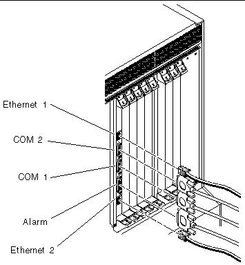
9. Plug all appropriate cables into the alarm rear transition card.
Tighten the screws on the cable to a torque of 0.23 N.m (2 in.-lb).
10. Get the replacement alarm card from the ship kit.
11. Verify that the ejection levers are unlocked.
You will not be able to install the card properly if the ejection levers are locked.
12. Go to the front of the server and install the replacement alarm card in the Netra CT server.
Refer to Inserting a Main Card for those instructions.
Copyright © 2003, Sun Microsystems, Inc. All rights reserved.