| C H A P T E R 8 |
|
Removing and Replacing Hot-Swappable Subassemblies |

|
Caution - If you are just powering on your Netra CT server, do not remove or install any components in the system until you have verified that the system is completely powered up. Refer to Section 2.1.1, Verifying Full Power-Up for more information. |
This chapter specifies procedures for the installation, removal, and replacement of hot-swappable Netra CT server subassemblies. It is organized as follows:
Consult the Netra CT Server Safety and Compliance Manual for safety information prior to performing the procedures in this chapter.
|
Note - Read Chapter 3 before performing the procedures in this chapter. |
This section tells you how to remove and replace a system status panel. The instructions provided here apply to the removal and replacement of the system status panel from both a Netra CT 410 server and a Netra CT 810 server.
1. Attach the antistatic wrist strap.
Refer to Section 1.2, Attaching the Antistatic Wrist Strap.
2. Go to the front of the Netra CT server and locate the system status panel.
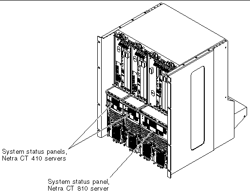
The location of the system status panel in the Netra CT 810 server and Netra CT 410 server is illustrated in FIGURE 8-1.
3. Using a No. 2 Phillips screwdriver, loosen the two captive screws that hold the system status panel in place.
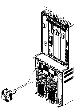
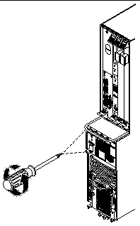
FIGURE 8-2 shows the location of the captive screws on the Netra CT 810 server, and FIGURE 8-3 shows the location of the captive screws on the Netra CT 410 server.
4. Pull the system status panel away from the Netra CT server and place it on the electrostatic discharge mat.
You may have to pull on the screws to remove the system status panel from the server.
1. Attach the antistatic wrist strap.
Refer to Section 1.2, Attaching the Antistatic Wrist Strap.
2. Carefully position the system status panel into place on the system.
FIGURE 8-4 shows how to position the panel into place on the Netra CT 810 server and FIGURE 8-5 shows how to position the panel into place on the Netra CT 410 server.
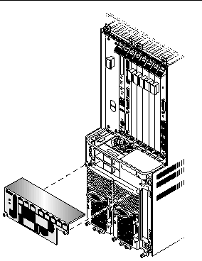
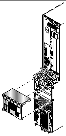
3. Push the system status panel into place against the server, paying special attention to the connector on the left side of the panel, making sure that the connector on the left back of the system status panel mates fully with the system controller board.
|
Note - Be careful not to press the power switch when you are pressing the left side of the system status panel into place. |
4. Using a No. 2 Phillips screwdriver, tighten the two captive screws to secure the system status panel to the system.
FIGURE 8-2 shows the location of the captive screws on the Netra CT 810 server, and FIGURE 8-3 shows the location of the captive screws on the Netra CT 410 server.
This section tells you how to remove and replace a system controller board. Each server has a single system controller board. You must remove the system status panel before you can access the system controller board.
|
Note - You must have the alarm card and host CPU card installed in the server before you can hot-swap the system controller board. |
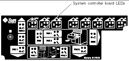
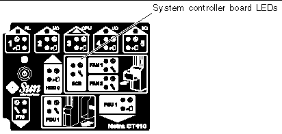
1. Go to the front of the system and use the system status panel to determine if the system controller board has failed.
FIGURE 8-6 shows the locations of the system controller board LEDs on the Netra CT 810 server, and FIGURE 8-7 shows the locations of the system controller board LEDs on the Netra CT 410 server.
2. Remove the system status panel as described in Section 8.1.1, Removing the System Status Panel.
Do not remove the antistatic wrist strap after you've removed the system status panel.
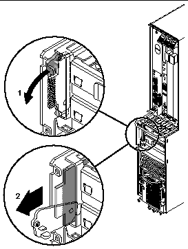
3. Pull down on the ejection lever to unseat the system controller board (FIGURE 8-8).
4. Slide the board out and place it on the electrostatic discharge mat.
1. Attach the antistatic wrist strap.
Refer to Section 1.2, Attaching the Antistatic Wrist Strap.
2. Push the ejection lever all the way down.
3. Line up the system controller board with its slot using the upper and lower rails, making sure that the component side of the board faces the left of the server.
The wide connector should be inserted first, as shown in FIGURE 8-9.
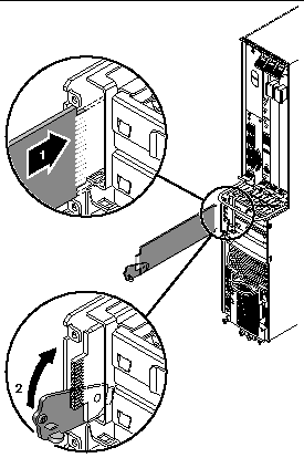
4. Slide the board into the slot (FIGURE 8-9).
5. Flip the ejection lever up as you slide the board into the slot to completely seat it in the card cage.
The notch on the ejection lever should fit into the cutout.
When the board is completely seated, you should see a brief flash of light behind the board.
6. Replace the system status panel, as described in Section 8.1.2, Replacing the System Status Panel.
Both the Netra CT 810 servers and the Netra CT 410 servers have two types of air filters: a power supply unit air filter, which filters the air going into the power supply, and a main air filter, which filters the air going into the server. Both air filters are located in the power supply unit. The power supply unit air filter is located at the front of the power supply unit and the main air filter is located in a tray at the top of the power supply unit.
Both sets of air filters should be replaced every three to six months. If your server environment is especially dirty, you may have to replace them more frequently. The power supply unit air filter must be in place for safe operation. Note that you do not have to power off the power supply unit or the system when removing or installing any of the air filters.
There is a single part number for the kit that contains both the main air filter and the power supply unit air filter for the Netra CT servers. The part number for the air filter kit is X7221A.
1. Squeeze in on the tabs at the sides of the power supply unit cover and remove the cover.
FIGURE 8-10 shows the location of the power supply unit cover for the Netra CT 810 server and FIGURE 8-11 shows the location of the power supply unit cover for the Netra CT 410 server.

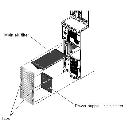
2. Remove the power supply unit air filter.
Refer to FIGURE 8-10 and FIGURE 8-11.
3. Slide the main air filter tray out of the power supply unit.
Refer to FIGURE 8-10 and FIGURE 8-11.
4. Remove the main air filter from the tray.
1. Insert the main air filter in the air filter tray.
Refer to FIGURE 8-10 and FIGURE 8-11.
2. Slide the air filter tray into the power supply unit.
3. Insert the power supply unit air filter into the power supply unit cover.
4. Replace the power supply unit cover on the power supply unit until it clicks into place.
The second power supply unit in a Netra CT 810 server is hot-swappable, as described in Section 1.5, FRU Categories. The remaining power supply unit in a Netra CT 810 server and the lone power supply unit in a Netra CT 410 server are cold-swappable. If you are replacing a hot-swappable power supply unit, then follow the instructions in this section; if you are replacing a cold-swappable power supply unit, then go to Section 10.5, Power Supply Unit.
Note that your Netra CT 810 server will continue to operate normally with only one power supply unit; however, you will not have complete redundancy for the power supplies until you replace the failed power supply unit.
The instructions for removing and replacing power supply unit is the same, regardless of whether they are AC or DC power supply units.
The part number for the AC power supply unit is F300-1543. The part number for the DC power supply unit is F300-1535.
1. Attach the antistatic wrist strap.
Refer to Section 1.2, Attaching the Antistatic Wrist Strap.
2. Determine the state of the power supply unit that you want to remove.
You may have to get troubleshooting information from the LEDs on the power supply unit itself to determine its state. Refer to Section 4.6, Troubleshooting a Power Supply Using the Power Supply Unit LEDs for more information.
3. Verify that the power supply unit that you want to remove is hot-swappable.
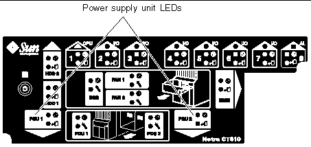
Use the power supply unit (PSU) LEDs on the system status panel to locate the power supply unit that can be removed. FIGURE 8-12 shows the location of the power supply unit LEDs on the Netra CT 810 server system status panel.
In a redundant system, a power supply unit is hot-swappable and can be removed only if the amber Okay to Remove LED ( ) on the system status panel is ON.
4. Push the purple locking mechanism up into the unlocked ( ) position.
FIGURE 8-13 shows the location of the locking mechanism for a power supply unit in a Netra CT 810 server. The two LEDs on the power supply unit should go off. In addition, after several seconds, the amber Okay to Remove LED ( ) on the system status panel for the remaining power supply unit in the Netra CT 810 server should go to OFF. This tells you that the remaining power supply unit is no longer hot-swappable as long as you have the first power supply unit disabled.
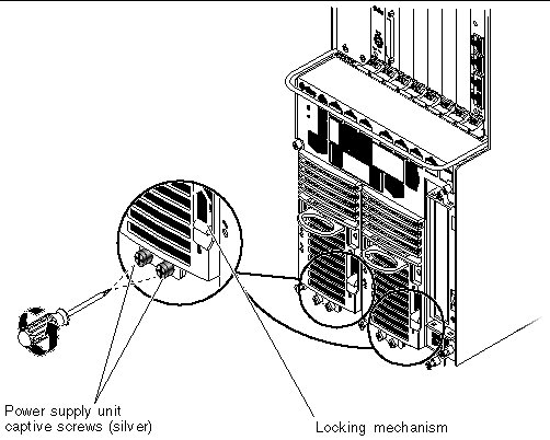
5. Using a No. 2 Phillips screwdriver, loosen the two silver captive screws at the base of the power supply unit.
FIGURE 8-13 shows the location of the captive screws for a power supply unit on a Netra CT 810 server.
|
Note - Do not loosen the black captive screws at the base of the system; those screws hold the server in place. |
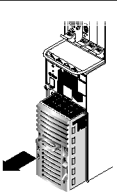
6. Grasp the handle on the power supply unit, slide it out of the server and place it on the electrostatic discharge mat.
1. Attach the antistatic wrist strap.
Refer to Section 1.2, Attaching the Antistatic Wrist Strap.
2. Slide the power supply unit into the slot.
3. Using a No. 2 Phillips screwdriver, tighten the two silver captive screws beneath the power supply unit to secure the power supply unit to the server.
FIGURE 8-13 shows the location of the captive screws for the power supply unit on a Netra CT 810 server.
4. Push the locking mechanism down into the locked ( ) position.
FIGURE 8-13 shows the location of the locking mechanisms for the power supply unit on a Netra CT 810 server.
5. Verify that the power supply unit you just installed is functioning properly.
FIGURE 8-12 shows the location of the power supply unit LEDs (PSU) on the system status panel on the Netra CT 810 server.
The amber LEDs ( ) on the system status panel for both power supply units in the Netra CT 810 server should go ON. This tells you that you have two functioning, redundant power supply units in the server, and either of them is now hot-swappable.
This section describes you how to remove and replace a fan tray in both the Netra CT 810 server and the Netra CT 410 server.
If the temperature rises above 158°F (70°C), the CPU card sends out a warning that the system is overheating. If the temperature rises above 167°F (75°C), then the system shuts down automatically. Note that the temperatures above are not ambient air temperatures, but rather the CPU temperatures that are monitored by a thermistor located under the heatsink on the host CPU card.
If one fan tray fails, you must replace the failed fan tray as soon as possible. Even though the system can run on one fan tray, if the temperature rises, a single fan tray may not be able to cool the system properly.
1. Go to the front of the system and use the system status panel to determine if a fan tray has failed.
FIGURE 8-15 shows the locations of the fan tray LEDs on the Netra CT 810 server and FIGURE 8-16 shows the locations of the fan tray LEDs on the Netra CT 410 server.
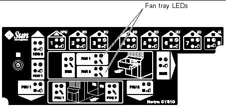
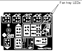
A fan tray has failed if the amber Fault LED ( ) on the system status panel is ON.
2. Make a note of which fan tray has failed.
You must remove the system status panel in order to access the fan trays, and you will not be able to determine which fan tray has failed after you've removed the system status panel.
3. Remove the system status panel from the system.
Refer to Section 8.1.1, Removing the System Status Panel for those instructions.
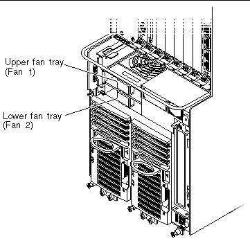
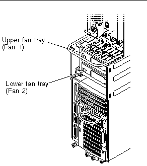
4. Locate the fan tray that has failed.
FIGURE 8-17 shows the locations of the fan trays in a Netra CT 810 server and FIGURE 8-18 shows the locations of the fan trays in a Netra CT 410 server.
5. Remove the fan tray from the system.
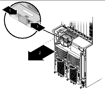
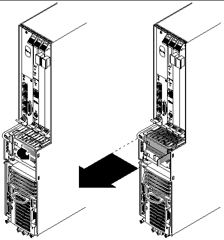
1. Insert the fan tray into the system:
2. Install the system status panel on the system.
Refer to Section 8.1.2, Replacing the System Status Panel for those instructions.
3. Verify that the fan tray LEDs are lit properly.
FIGURE 8-15 shows the locations of the fan tray LEDs on the Netra CT 810 server and FIGURE 8-16 shows the locations of the fan tray LEDs on the Netra CT 410 server.
A fan tray is functioning properly if the amber Fault LED ( ) on the system status panel is OFF and the green Power LED (
 ) is ON.
Copyright © 2003, Sun Microsystems, Inc. All rights reserved.