| Exit Print View | |
Sun Fire X4800 Server Rack Mounting and Shipping Bracket User's Guide |

|
About This Documentation (PDF and HTML)
Installing the Server Hardware
Location of the Rack Mounting Kit and the Shipping Bracket Kit
Installing the Server In a Rack
How to Install the Rack Mounting Hardware in the Rack
How to Insert the Server Into the Rack
Removing and Installing Shipping Brackets
This procedure describes how to remove components from your server so that two persons can lift it into the rack. If you are going to use a mechanical lift, you do not need to perform this procedure.
 | Caution - Circuit boards and hard drives contain electronic components that are extremely sensitive to
static electricity. Ordinary amounts of static electricity from clothing or the work environment
can destroy the components located on these devices. Do not touch the components
without antistatic precautions, especially along the connector edges. For more information, refer to
|
Note - This procedure assumes that the server is powered off and all cables are disconnected.
Remove the CPU modules from the front of the chassis.
The chassis contains four CPU module slots; each must have a CPU module or a filler panel.
Note - Because of their light weight, there is no need to remove filler panels.

 | Caution - To prevent system failure, you must return CPU module slots to their original locations. Mark CPU module slot locations carefully before removing them from the chassis. |
For each CPU module:
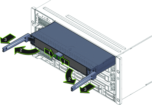
Pinch the green tabs to release the ejectors (1).
Pull both ejectors out to release the module (2).
 | Caution - When the module is partway out of the chassis, close the ejectors, and grasp the module. Do not handle the module by the ejectors. |
Gently slide the module forward until it is clear of the chassis (3).
 | Caution - The CPU module is heavy. Use two hands. |
Place the CPU module on an antistatic mat.
Remove the four power supplies from the front of the chassis.
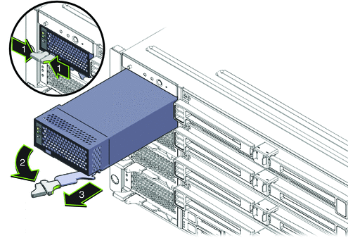
Pinch the handle to release the lever (1).
Pull the lever (2) to release the power supply.
Slide the power supply out of the chassis (3).

Remove the PCIe express modules from the back of the chassis.
The upper bays can be used as a hand hold when moving the chassis.

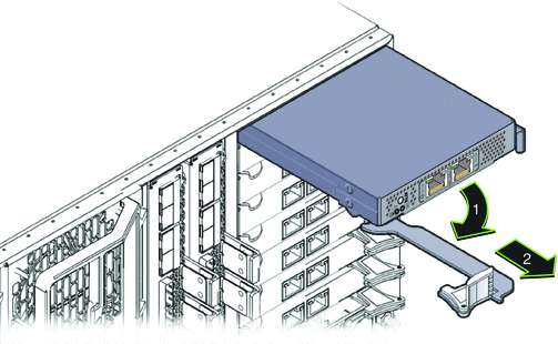
Rotate the lever (1) to release the module.
Slide the module out of the chassis (2).
Remove the upper left fan module (FM2) if necessary.
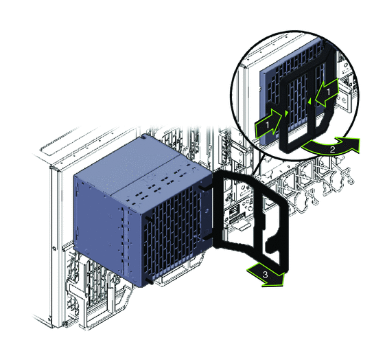
Squeeze the clamp (1) to release the fan module (2), then pull it from the chassis (3).
You can use the recess as a hand-hold when moving the chassis.

Reverse these steps to reassemble the server after it is installed in the rack.