Preparing the Network and Connectivity Specification
Before you install and configure the Java ES components that appear in your deployment architecture, the computers must be attached to the network and assigned IP addresses. Preparing the network for a Java ES deployment can be a complex task that requires you to create several subnets to implement the security zones described in the architecture. Before you begin to set up the network, prepare a network and connectivity specification that maps all of the network connections needed to implement the deployment architecture.
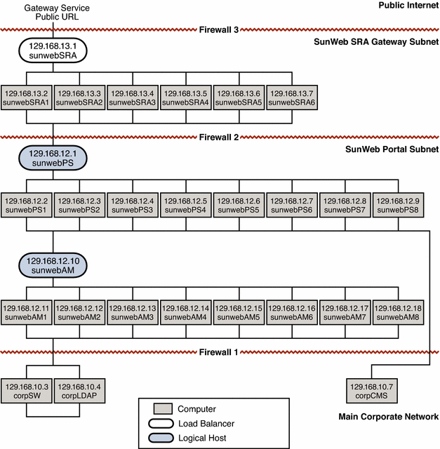
A network and connectivity specification is typically a graphical representation of the required network configuration. The following figure is a graphical representation of the network configuration required to implement the SunWeb architecture.
Note –
The IP addresses that appear in the following figure are not the addresses used in the actual SunWeb deployment. The IP addresses in the figure are used only to illustrate the concept of subnet configuration.
The network topology illustrated in the following figure implements the security strategies described in Choosing Security Strategies for the SunWeb Architecture. In particular, the following figure shows how the network and connectivity specification assigns private IP addresses to establish the secure network topology.
Figure 4–1 Network and Connectivity Specification

The computers running the gateway service and the computers running the portal service are on separate subnets. The existing corporate services are already deployed on the main corporate network, and appropriate security measures that allow the SunWeb portal controlled access to the information on the main corporate network are in place.
Access from the public Internet is restricted to HTTPS (SSL) access to the load balancer for the gateway service. Certificates are used.
For employees accessing the portal service over the public Internet only the load balancer in the DMZ (subnet 129.168.13.x) is actually exposed as shown in Figure 4–1. Everything else, according to the philosophy of minimizing the surface of attack, is hidden through use of private IP addresses.
Since the DMZ contains the SRA service that is accessed by Sun employees over the public internet, the IP address for the load balancer sunwebSRA is a normal IP address, which is accessible from the Internet. The IP address shown for this load balancer in Figure 4–1 is 129.168.13.1. When this load balancer is configured, however, this address is replaced with the real, publicly accessible address for the gateway service.
All of the other hardware in this zone is assigned 129.168.13.xx IP addresses, which are private addresses. These private addresses are not recognized by the Internet and are not routed outside the corporate network.
The only bridge between the DMZ and the portal service subnet is the load balancer, which controls the traffic between the subnets. Therefore, if the DMZ is compromised there is no direct route to the portal service subnet.
- © 2010, Oracle Corporation and/or its affiliates
