| Exit Print View | |
Sun Datacenter InfiniBand Switch 72 Topic Set |

|
Documentation, Support, and Training
Understanding Service Procedures
Inspect the Power Supply Hardware
Inspect the Power Supply Connectors
Servicing the InfiniBand Cables
Inspecting an InfiniBand Cable
Inspect the InfiniBand Cable Hardware
Inspect the InfiniBand Cable Connectors
Identify the prerequisite and subsequent service tasks you must perform in conjunction with this procedure.
Use a No. 1 Phillips screwdriver to remove the eight screws that secure the C-shaped brackets at the rear sides of the switch chassis.
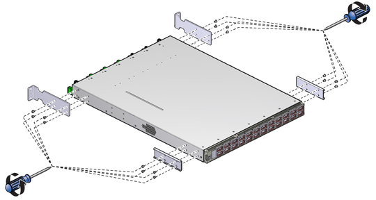
Remove the eight screws that secure the long front brackets at the front sides of the switch chassis.
Remove the 16 screws that secure the top cover to the chassis.
There are five screws on each side and six screws across the top front of the cover.
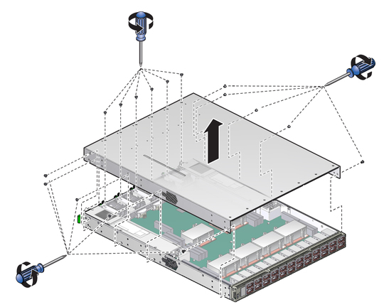
Slide the cover forward and lift it off.
Lift up slightly on the clip that retains the battery and release the battery from the main board.
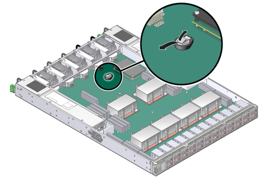
Properly dispose of the old battery.
Unwrap the replacement battery from its antistatic packaging.
Install the replacement battery into the main board with the + side up.
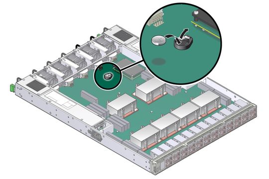
Orient the cover over the chassis and lower it in place.
Slide the cover rearward so that it engages at the rear panel.
Ensure that the screw holes in the cover align with the holes in the chassis.
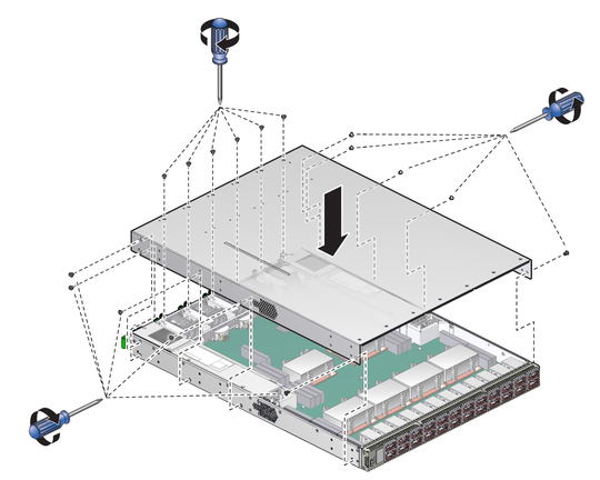
Use a No. 1 Phillips screwdriver to install the 16 screws that secure the cover to the chassis.
Use eight screws to attach the two long front brackets to the front sides of the chassis.
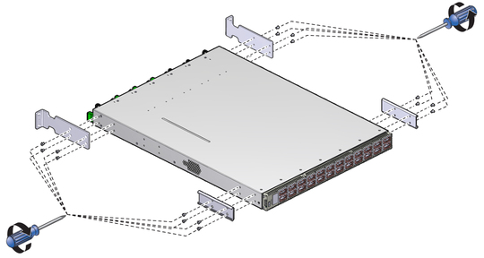
Use eight screws to attach the two C-shaped brackets to the rear sides of the chassis.
Install the switch into the rack.