| C H A P T E R 1 |
|
Sun Blade T6340 Server Module Product Description |
This chapter provides an overview of the features of the Sun Blade T6340 Server Module. (A server module is also known as a blade.)
The following topics are covered:
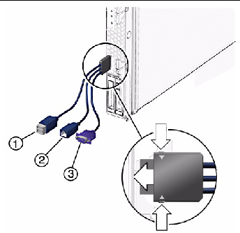
FIGURE 1-1, FIGURE 1-2, and FIGURE 1-3 show the main Sun Blade T6340 components and some basic connections to the chassis. For information about connectivity to system fans, PCI ExpressModules, Ethernet modules, and other components, see the chassis documentation at:
http://docs.sun.com/app/docs/prod/blade.t6340
FIGURE 1-1 Sun Blade T6340 Server Module With Chassis
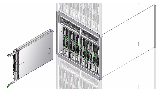
TABLE 1-1 lists the Sun Blade T6340 server module features. TABLE 1-2 lists some of chassis input-output features.
FIGURE 1-2 Front and Rear Panels
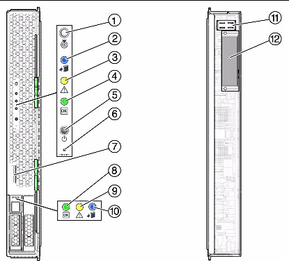
FIGURE 1-3 Cable Dongle Connectors

|
Caution - If you are using the older 4-cable dongle(UCP-4), do notuse the RJ-45 connector with the Sun Blade T6340 server module. Use the DB-9 connector for serial connections. |
Some USB connectors are thick and may distort or damage the connector when you try to connect two USB cables. You can use a USB hub to avoid this problem.
| Note - For information about connecting to the server module refer to the Sun Blade T6340 Server Module Installation and Administration Guide, 820-3900. |
|
Two 1Gb Ethernet ports. Support for up to two 10Gb Ethernet ports through Fabric Expansion Modules (FEM)
|
|
|
Two 8-lane ports connect to chassis midplane. Can support up to two 8-lane PCI ExpressModules (PCI EM). (FIGURE 1-5) |
|
|
Four channels for remote storage connect from the RAID Express Module (REM) to the chassis midplane. |
|
|
ILOM management controller on the service processor. CLI management (ssh only) and N1 system manager support. DMTF CLI and ALOM-CMT compatible CLI available through ssh. Remote console (remote KVMS) is configurable through OpenBoot PROM and ILOM. |
|
For more information about chassis features and controls, refer to the service manual for your blade chassis at:
http://docs.sun.com/app/docs/prod/blade.srvr
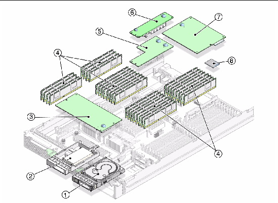
Sun Blade T6340 Server Module Field-Replaceable Units (FRUs) are shown in FIGURE 1-4.
FIGURE 1-4 Field-Replaceable Units
|
Up to two SFF SAS or SATA 2.5-inch hard drives in mounting bracket; HDD0 and HDD1. |
||
|
Section 4.6.3, Installing and Removing the Sun Blade RAID 5 Expansion Module Battery Tray |
||
|
Service processor. Controls the host power and monitors host system events (power and environmental). Socketed EEPROM stores system configuration, all Ethernet MAC addresses, and the host ID. |
||
|
Section 4.8, Removing and Replacing a Fabric ExpressModule (FEM) |
||
|
Section 4.8, Removing and Replacing a Fabric ExpressModule (FEM) |
||
|
RAID expansion module (REM).
|
Section 4.6, Replacing and Installing the Sun Blade RAID 5 Expansion Module |
|
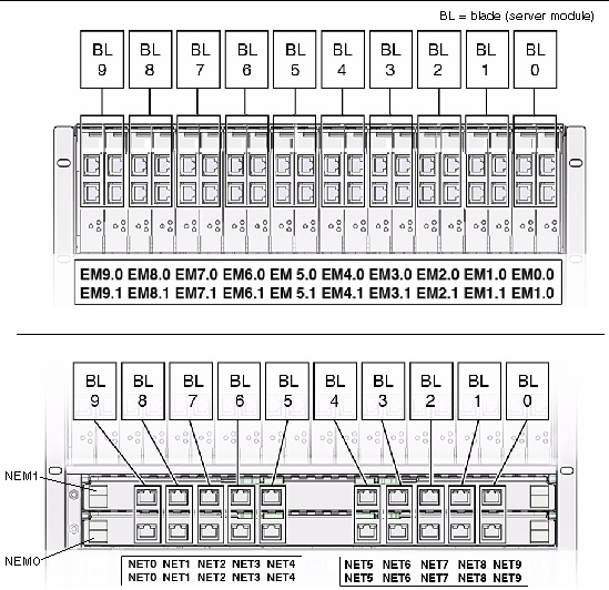
FIGURE 1-5 PCI Express and Ethernet Connections on a Sun Blade 6000 Modular System
The UltraSPARC® T2 Plus multicore processor is the basis of the Sun Blade T6340 server module. This server module supports two UltraSPARC T2 CPU modules.
Each processor has four, six, or eight UltraSPARC cores. Each core equates to a 64-bit execution pipeline capable of running eight threads. The result is that the 8-core processor handles up to 128 active threads concurrently. For more information about the UltraSPARC® T2 Plus multicore processors, go to:
http://www.sun.com/processors/UltraSPARC-T2/features.xml
http://www.sun.com/servers/wp.jsp?tab=1
By attaching one or more external storage devices to the Sun Blade T6340 server module, you can use a redundant array of independent drives (RAID) to configure system drive storage in a variety of different RAID levels.
As shipped, the Sun Blade T6320 Server hard drives are not configured for RAID. To make a disk part of a RAID array while preserving the data on the drive, add the drive to a mirrored RAID set (also known as hardware RAID Level 1).
Before configuring RAID, you must configure a RAID expansion module (REM).The Sun Blade T6340 Server Module supports two REMs, the Sun Blade RAID 5 and Sun Blade RAID 0/1 G2 Expansion Modules.
Refer to the following for RAID configuration instructions:
The Sun Blade RAID 5 Expansion Module supports RAID levels 0, 1, 1E, 10, 5, or 6 with global or dedicated hot spares.
| Note - When a Sun Blade RAID 5 Expansion Module is installed, one SAS drive must be installed in Hard Disk Drive (HDD) Slot HDD1. The Sun Blade RAID 5 Expansion Module external battery tray must be installed in Slot HDD0 (see Section 4.6, Replacing and Installing the Sun Blade RAID 5 Expansion Module). To enable RAID 0, 1, 5, or 10, you must also install a Sun Blade 6000 Disk Module, which supports up to eight SAS drives. |
This task is for configurations that do not use the Sun Blade 6000 Disk Module
1. Enter the following command and options:
| Note - You can safely ignore the mkdir failed message. |
2. Perform the necessary tasks to configure the drive. Such tasks might include the following:
These tasks are covered in the Solaris OS administration documentation. For additional drive verification, use SunVTS. Refer to the SunVTS and Solaris documentation at http://docs.sun.com for details.
The Sun Blade RAID 0/1 G2 Expansion Module supports RAID 1 (two mirrored disks with an optional hot spare) or RAID 1E (three or more mirrored disks with one or two hot spares).
For more information, refer to the Sun Blade G2 RAID 0/1 Expansion Module Installation Guide, 820-5448 at:
http://dlc.sun.com/pdf/820-5448-10/820-5448-10.pdf
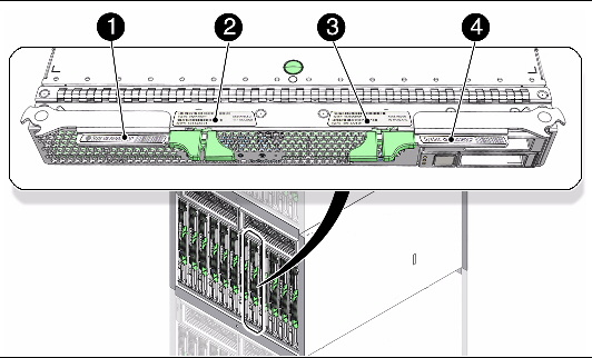
To obtain support for your system, you need the serial number. The serial number is located on a sticker on the front of the server module (FIGURE 1-6).
FIGURE 1-6 Serial Number and MAC Address Locations
You can type the ILOM show /SYS command or the ALOM CMT showplatform command to obtain the chassis serial number. Both examples are shown below.
sc> showplatform SUNW, Sun Blade T6340 Server Module Blade Serial Number: 1005LCB-08268N0008 Chassis Serial Number: 1005LCB-0804YM04XE Slot Number: 5 Domain Status ------ ------ S0 Running sc> |
Documentation for the Sun Blade T6340 server module, and related hardware and software is listed in Related Documentation.
The following resources are also available.
Copyright © 2010, Oracle and/or its affiliates. All rights reserved.