| Sun Blade 6048 Modular System Service Manual |
| C H A P T E R 1 |
|
Introduction to the Sun Blade 6048 Modular System |
This chapter contains an overview of the Sun Blade 6048 modular system.
The Sun Blade 6048 modular system is a blade server system optimized for high-performance applications that place great demands on CPU performance, memory capacity, and I/O bandwidth. The system supports up to 48 server modules (also known as blades) per chassis. The system design provides a power and cooling infrastructure to support current and future CPU and memory configurations, ensuring that the chassis lifecycle will span multiple generations of server module upgrades. The system provides a unified yet flexible architecture that enables you to consolidate multiple operating environments and applications.
This chapter includes the following sections:
The Sun Blade 6048 modular system includes four chassis shelves. Each shelf contains slots for 12 server modules accessible from the front of the chassis, along with two power supplies and two front fan modules (located inside the power supplies). At the rear of the each chassis shelf are up to 24 PCI ExpressModules (PCI EMs), two network express modules (NEMs), one chassis management module (CMM), and six fan modules. All active chassis components that are critical to system operation are configured for redundancy.
The Sun Blade 6048 modular system is designed for ease of service by either the customer for user-upgradeable components or by authorized service personnel.
FIGURE 1-1 shows the front and rear views of the chassis.
FIGURE 1-1 Front and Rear Views of Sun Blade Modular System Chassis

FIGURE 1-2 shows the locations of components for each chassis shelf.
FIGURE 1-2 Single Shelf Component View

The Sun Blade 6048 modular system architecture includes capacity for up to 48
hot-pluggable server modules.
Refer to the documentation that comes with the server module for specific information about each server module.
All I/O is PCI Express based on customer-replaceable units (CRUs) called PCI ExpressModules (PCI EMs) and network express modules (NEMs).
The PCI ExpressModules (PCI EMs) are based on the PCI Express industry-standard form factor for PCI EMs. The PCI EMs provide dedicated I/O functions on a per- server module basis. There are two PCI EMs for each server module, for up to 24 PCI EMs per chassis shelf.
You can customize the server module and PCI EM configurations in the chassis. For example, one server module can be configured with redundant Fibre Channel PCI EMs, while another server module can have a single Fibre Channel PCI EM and a single InfiniBand PCI EM. The PCI EMs provide a maximum of 4 Gbytes per second of I/O per module.
Up to two NEMs per system shelf offer pass-through Gigabit Ethernet connections to the server modules. Designed within a Sun proprietary form factor, these switchless networking devices provide a dual Gigabit NIC for each server module. There are up to two RJ-45 Ethernet interfaces per server module providing 10/100/1000BASE-T ports at the chassis rear.
The Sun Blade 6048 modular system chassis management module (CMM) manages a portion of the Sun Blade 6048 chassis. This section provides an overview of the CMM functionality. For specific information about system management using the CMM Integrated Lights Out Manager (ILOM), see the Sun Integrated Lights Out Manager 2.0 User’s Guide.
The CMM provides an RJ-45 serial interface and two RJ-45 Ethernet connectors. The CMM is also compatible with Sun N1 System Manager (SM) software and some third-party management software.
The CMM provides the following:
The CMM ILOM provides the following features:
The CLI provides an interface to view the status of the components shown in TABLE 1-1.
The Sun Integrated Lights Out Manager (ILOM) firmware is preinstalled on the CMM, and it initializes as soon as power is applied to the chassis. ILOM provides a command-line interface (CLI) and a web interface that you can use to administer and diagnose local or remote systems.
Out-of-band communication is provided through the serial port for CLI console access and through a dedicated Ethernet for CLI via SSH or the web interface. In-band communication is provided via the host operating system. ILOM runs on the CMM independently of the rest of the system, using the system’s standby power. Therefore, ILOM continues to function when the system’s operating system goes offline or when the system is powered off.
See the Sun Integrated Lights Out Manager 2.0 User’s Guide for more information about the CMM ILOM.
The figures and tables in this section describe the paths in the CMM ILOM CLI that you can use to locate component information. You can also use the ILOM web interface to access this information. Refer to the Sun Integrated Lights Out Manager 2.0 User’s Guide for more information.
Use the show command with the component location shown in this section to view information about the component.
For example, show /CH/PS0 gives you the following information about power supply module 0:
-> show /CH/PS0 /CH/PS0 Targets: STATUS S0 S1 S2 T_AMB FAN0 FAN1 FAN2 FAN3 FAN_FAIL V+12V V+3_3V I+3_3V V+3_3V_FAULT T_AMB_FAULT T_AMB_WARN Properties: type = Power Supply Commands: cd show |
The information available for each component varies, depending on the component sensor type. See Appendix A for ILOM sensor information.
FIGURE 1-3 and TABLE 1-2 show the nomenclature used in the CMM ILOM to access information for front chassis components.

FIGURE 1-4 and TABLE 1-3 show the nomenclature used in the CMM ILOM to access information for rear chassis components.

|
NEM (n = 0) [1] |
FIGURE 1-5 and TABLE 1-4 show the nomenclature used in the CMM ILOM to access information for rear chassis components.

The Sun Blade 6048 modular system is designed with hardware and software features that surpass those of conventional servers. These features are summarized in TABLE 1-5. Additional system specifications can be found in the Sun Blade 6048 Modular System Site Planning Guide.
The Sun Blade 6048 modular system includes many server module-centric and chassis-wide features that increase reliability, availability, and serviceability (RAS). These RAS features are aspects of a system’s design that affect its ability to operate continuously and to minimize the time necessary to service the system. Reliability refers to the system’s ability to operate continuously without failures and to maintain data integrity. Availability refers to the ability of the system to recover to an operational state after a failure, with minimal impact.
Serviceability relates to the time it takes to restore a system to service following a component failure. Together, the RAS features of the Sun Blade 6048 modular system provide for near continuous operation.
This section includes the following topics:
Sun Blade 6048 modular system hardware supports hot-plugging of the chassis-mounted server modules (blades). Using the proper software commands, you can install or remove these components while the system is running. Hot-plug technology significantly increases the system’s serviceability and availability by providing the ability to replace these components without service disruption.
Refer your server module documentation for information about software commands for hot-pluggable components.
Sun Blade 6048 modular system hardware supports hot-swapping of the network express modules (NEMs), PCI ExpressModules (PCI EMs), chassis management module (CMM), both front and rear fan modules, and power supply modules. You can install or remove these components while the system is running, without using any software commands.
The Sun Blade 6048 modular system provides redundant components that enable the system to continue operations if one of the associated components fails. This separation of functions minimizes the impact of component problems and servicing.
The redundant components include the following:
The following modules might be redundant, depending on the system configuration:
The Sun Blade 6048 modular system features an environmental monitoring subsystem designed to protect components against the following:
Temperature sensors located throughout the system monitor the ambient temperature of the chassis and internal components. The software and hardware ensure that the temperatures within the chassis do not exceed predetermined safe operating ranges. If the temperature observed by a sensor falls below or rises above a set threshold, the monitoring software subsystem lights the amber Service Required indicators on the front and back of the system. If the temperature condition persists and reaches a critical threshold, the system might initiate a graceful system shutdown. See Section 1.6.6, LED Indicators and Buttons for more information about the system LEDs.
All error and warning messages are sent to the chassis management module (CMM), and are logged in the Sun ILOM log file. Additionally, some customer-replaceable units (CRUs), such as power supplies and fans, provide LEDs that indicate a failure within the CRU. See Section 2.3.1, Chassis Shelf Faults for more information about chassis fault LEDs.
The Sun Blade 6048 chassis system indicators follow the ANSI Vita 40-2003 Status Indicator Standard as well as Sun Microsystems Service Indicator Application Guidelines.
There are three types of indicators for chassis components: Normal (green), Fault (amber), and Locate (white), although not every customer-replaceable unit (CRU) will have all indicator types. The subset of indicators and functionality chosen for each component depends on what is appropriate for a given CRU.
See the documentation for the server modules for information about server module LEDs.
TABLE 1-7 summarizes all service indicators and their modes in the Sun Blade 6048 system. The indicators on the CMM are the same as the chassis service indicators. The slow-blink amber function for the PCI Express Modules is a Locate function that is specified by the PCI ExpressModule standard.
The LED states are displayed as follows:
TABLE 1-8 shows the functions of the system LEDs and buttons.
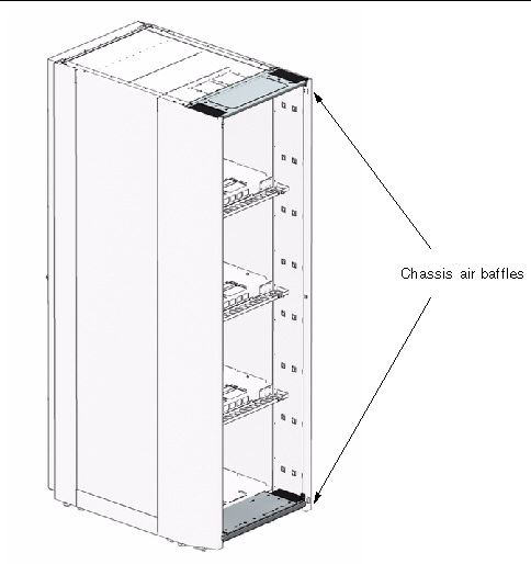
An updated chassis is now available for the Sun Blade 6048 modular system. This chassis enables installation of the Sun Blade cooling doors and contains a PCIe 2.0 compatible midplane.
You can identify the updated chassis in two ways:
FIGURE 1-6 Air Baffles on Updated Chassis
|
1. Log in to the ILOM CLI as an Administrator or Operator.
2. At the command prompt, type:
The chassis manufacturing part number will be displayed in the product_part_number field.
|
1. Log in to the ILOM web interface as an Administrator or Operator.
2. Select System Information --> Components.
The Component Management page appears.
3. Click on /CH in the Component Management Status table.
A dialog box appears with information about the chassis.
The chassis manufacturing part number will be displayed in the product_part_number field.
| Sun Blade 6048 Modular System Service Manual | 820-2863-13 |
Copyright © 2009 Sun Microsystems, Inc. All rights reserved.
 View Component Information Using the CLI