| C H A P T E R 2 |
|
Fault Management |
This chapter contains information about the following topics related to fault management on the Sun Blade 6048 modular system.
The fault management software of the Sun Blade 6048 modular system monitors hardware health and diagnoses and reports hardware failures on system components. Fault management also monitors environmental conditions and reports when the systems environment is outside acceptable parameters. Various sensors on the system chassis shelf, the power supplies (PSUs), server modules, and fans are continuously monitored. When a sensor registers a problem, the fault management software, which runs on the chassis management module (CMM), is notified.
Fault management then diagnoses the problem. If it determines that a hardware or environmental failure has occurred, fault management lights the Service Action Required LED on the affected component. The ILOM management interfaces are updated to reflect the failure (the fault), and the failure is recorded as a fault in the event log.
When a system component experiences a hardware failure, it is called an internal fault; that is, the fault is the result of a problem with the hardware of the Sun Blade 6048 modular system itself. Internal faults are cleared when a repair action takes place, most likely the replacement of the failed component.
There are some faults, however, that are external faults. In these cases, the system hardware has not failed, but a condition external to the system is causing a potential problem. If, for example, the ambient air temperature (external to the chassis) exceeds a certain threshold, it is a fault because it can adversely affect the operation of the system if not corrected. External faults are autoclearing; they are cleared when the external condition no longer exists. Nonetheless, an external fault can, if not attended to, cause components or the system as a whole to shut down.
Fault management monitors the following system component.
| Note - For information about faults for other system components such as NEMs, PCI EMs, and blades, refer to the documentation for that component. |
There are three ways to tell when a fault has occurred somewhere in the system:
When a component experiences a hardware failure (enters a fault state), fault management illuminates the Service Action Required (amber) LED on that component. In addition, fault management illuminates the Service Action Required LEDs on the system chassis shelf (both front and back) when any system component is in a faulted state.
Since a Service Action Required LED indicates a hardware failure, it remains illuminated until fault management detects that the failed hardware has been replaced or repaired. The chassis shelf Service Action Required LEDs, which serve as summary indicators for all component faults, remain illuminated as long as any system component remains in a faulted state.
If the chassis Service Action Required LEDs are illuminated but no other system component has a lit Service Action Required LED, then fault management has diagnosed an external fault: a problem outside the system that potentially affects the system as a whole. For example, if the external ambient air temperature exceeds
45o C, a fault is declared and the system shuts down although there is nothing physically wrong with any system hardware.
Refer to Section 2.3.1, Chassis Shelf Faults for information about the external conditions that can cause these chassis faults.
The power supply units (PSUs) are a special case; they monitor their own fault status and control their own Service Action Required LEDs. The fault management software cannot turn the PSU LEDs on or off. However, because fault management is monitoring sensors on the PSUs, it is notified when a PSU fault occurs. Fault management illuminates the chassis shelf Service Action Required LEDs and notes the fault occurrence in the ILOM management interfaces and in the event log.
Note that it is possible for a PSU to extinguish its Service Action Required LED (declare that the fault is cleared), but for fault management to continue to assert that the PSU is still in a faulted state. If this happens, the ILOM management interfaces, the chassis shelf Service Action Required LEDs, and the event log reflect that the faulted state is ongoing.
Refer to Section 2.3.2, Power Supply Module Faults for more information.
You can monitor chassis shelf and component faults from the ILOM CLI or the web interface.
| Note - Refer to the Sun Integrated Lights Out Manager 2.0 User’s Guide for information about the object namespace and how to identify the targets and properties that might pertain to faults. |
To obtain sensor readings using the CLI:
1. Establish a local serial console connection or SSH connection to the CMM, and log in to the ILOM.
2. Issue the appropriate show command to display information about system components.
For example, if a power-supply AC-1 light is lit, you would issue the following command:
> show /CH/PS0/S1/AC_FAIL /CH/PS0/S1/AC_FAIL Targets: Properties: type = Voltage class = Discrete Sensor value = Predictive Failure Asserted Commands: cd show |
The value = Predictive Failure Asserted shows the faulted power supply. Since one of the power supplies in power supply module 0 has failed, the entire power supply module will need to be replaced.
In the ILOM web interface, you can obtain instantaneous sensor readings about system FRUs (field-replaceable units) or other system inventory on the System Monitoring -> Sensor Readings page.
To obtain sensor readings from the ILOM web interface:
1. Open a web browser, and type the IP address of the server SP or CMM.
The Login page for the ILOM web interface appears.
2. In the ILOM Login page, enter a user name and password, and then click OK.
The ILOM web interface appears.
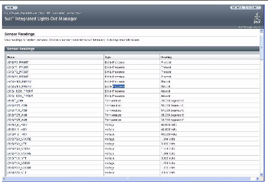
3. In the web interface page, click System Monitoring -> Sensors Readings.
The Sensor Readings page appears.
FIGURE 2-1 Sensor Readings Page
| Note - If the server is powered off, many components will appear as “no reading.” |
4. In the Sensor Readings page, do the following:
a. Locate the name of the sensor you want to view.
b. Click the name of the sensor to view the property values associated with that sensor.
For specific details about the type of discrete sensor targets you can access, as well as the paths to access them, consult the user documentation provided with the Sun server platform.
Faults are recorded in the system event log, which can be viewed from the ILOM CLI or web interface.
To view or clear events in the system event log using the ILOM CLI:
1. Establish a local serial console connection or SSH connection to the CMM, and log in to the ILOM.
2. Type the following command paths to set the working directory:
3. Type the following command path to display the event log list.
The contents of the event log appears. An example follows.
4. In the event log, perform any of the following tasks:
A confirmation message appears.
To view or clear events in the ILOM event log using the ILOM web interface:
1. Open a web browser, and type the IP address of the server CMM.
The Login page for the ILOM web interface appears.
2. In the ILOM Login page, enter a user name and password, and then click OK.
The ILOM web interface appears.
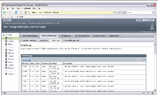
3. In the web interface page, select System Monitoring -> Event Logs.
FIGURE 2-2 ILOM Web Interface Event Log
4. In the Event Log page, perform any of the following:
Note that selecting a larger number of entries might cause the web interface to respond more slowly than selecting a smaller number of entries.
When a hardware failure occurs, the following actions take place:
The chassis shelf Service Action Required LEDs serve as summary indicators, notifying you that a hardware failure has occurred on one (or more) of the components in the chassis shelf.
See Section 2.2.3, Monitoring the Event Log or the Sun Integrated Lights Out Manager 2.0 User’s Guide for more information about reading component sensors and the event log.
The following sections contain further details on identifying faults in the system or specific components:
Chassis shelf faults are external faults: There is no hardware failure, but an external condition exists that can adversely affect the operation of the system. Because they are external, chassis shelf faults are auto-clearing; when fault management detects that the external condition has returned to within normal parameters, it clears the fault.
A fault is declared, and the chassis shelf Temperature Fail LEDs are illuminated when the external condition represents a potential hazard to the system. It is possible for an external fault to force a shutdown of the entire system.
The Chassis Shelf Service Action Required LED also lights when there is a fault on a chassis shelf component.
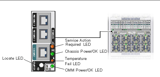
FIGURE 2-3 and FIGURE 2-4 show the location of the LEDs on the front and rear of the chassis.
FIGURE 2-3 Front Chassis Shelf Fault Indicators
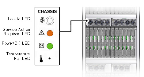
FIGURE 2-4 Rear Chassis Shelf Fault Indicators
If the Service Action Required LED is lit on the FIM or CMM, check the indicators on the power supplies and fan modules to see if one of these is also lit. Refer to the following sections for more information.
If a blade Service Action Required LED is lit, refer to the blade documentation for servicing the blade.
The chassis shelf Temperature Fail LED light turns on when at least one of the ambient temperature sensors in the power supply modules reaches 40o C, and shuts down the chassis shelf when the temperature reaches 45o C. See TABLE 2-3 for information about viewing this sensor information.
See the Sun Integrated Lights Out Manager 2.0 User’s Guide for more information about reading this and other chassis shelf sensors.
There are three power supplies located within each power supply module. The AC-0 LED corresponds to power supply 0 within the power supply module, AC-1 corresponds to power supply 1, and AC-2 corresponds to power supply 2.
If you do not need the full 8400W of power from the power supplies, you can connect only two of the total three plugs to the AC0 and AC1 connectors for each power supply. Do not connect AC2.
When only two of the available three plugs is connected to the power supplies,
5600 W of power will be supplied to the chassis. The LEDs and ILOM will show different readings than for the three power cord connections. See the notes in the following sections for the differences in configurations.
FIGURE 2-5 9000W Power Supply LED Location
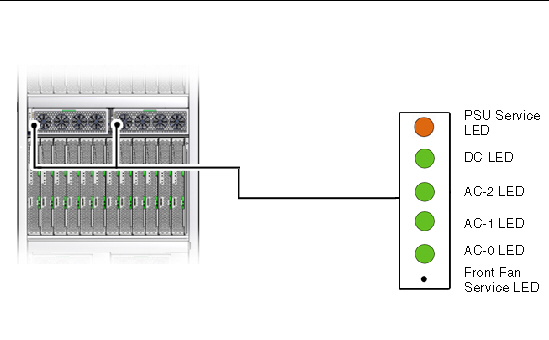
TABLE 2-2 shows the operation of the LEDs during normal operation or when a fault has occurred. Refer to the appropriate sensor table to find the location of the fault in the ILOM CLI.
|
See Appendix A |
|||||||
|
Over current, over voltage, or over temperature warning fault |
|||||||
If the power supply module LEDs indicate that a power supply or front fan failure has occurred, you can verify the fault by viewing the appropriate sensor through the ILOM CLI. See the Sun Integrated Lights Out 2.0 Manager User’s Guide and Appendix A for details on locating and reading the sensors in the ILOM.
Unless noted otherwise, the sensors shown in the following tables will display the following value if a fault has occurred:
| Note - If you are using two power cords per power supply, the ILOM readings will be different. Refer to Section A.2, ILOM Behavior With Two Power Cord Configuration for more information. |
The Sun Blade 6048 chassis shelf contains six rear fans.
FIGURE 2-6 Rear Fan LED Location
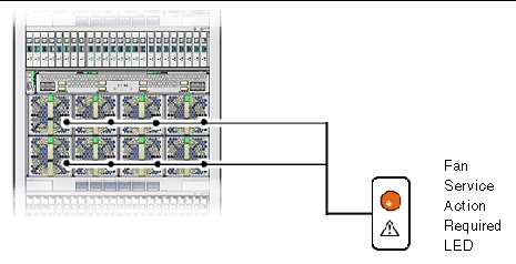
The rear fan fault LEDs indicate when a failure has occurred on a fan module. The source of the failure could be mechanical, electrical, or the result of a midplane controller failure.
Use the following command to view the sensor for a rear fan fault:
The variable n represents the fan module number. For example, /CH/FM1/FAIL indicates a fan failure in fan module 1.
See the Sun Integrated Lights Out Manager 2.0 User’s Guide and Appendix A for more information about reading this and other rear fan sensors.
When a fault indicates a hardware failure, the recommended method for clearing the fault is to replace the failed component.
To replace a failed component:
1. Determine which system component has experienced a hardware failure.
Look at the Service Action Required LEDs and the event log to get information about the component failure.
See Section 2.3, Determining That Hardware Has Failed.
2. Remove and replace the failed component.
Refer to the instructions in Chapter 4.
3. Monitor the component LEDs to confirm that the fault is cleared.
Copyright © 2009 Sun Microsystems, Inc. All rights reserved.