| Sun Blade 6048 Modular System Service Manual |
| C H A P T E R 4 |
|
Replacing System Components |
This chapter contains information and procedures for servicing the Sun Blade 6048 server module hardware, including component removal and replacement procedures.
The following topics are covered in this chapter:
The following procedures describe how to replace customer-replaceable unit (CRU) components:
You will need to replace a front fan module or power supply module if the module fails. A front fan module is located within each of the power supply modules, so you will need to remove the power supply associated with the fan module before replacing the module.
Do not leave a power supply slot vacant. Power supplies have integrated fans that will continue to supply cooling air even when the power supply is off. You can remove and replace a power supply from a powered-off system or from a powered-on system using a hot-swap procedure.
Use the following procedures to install a power supply into the corresponding vacant slot.
FIGURE 4-1 shows how to remove the power supplies and front fan modules.
| Note - Remove only one power supply at a time. One power supply must be in the system at all times to supply power to the system. |
FIGURE 4-1 Removing a Power Supply and Front Fan Module

| Note - You will need to replace the power supply that you removed within one minute to ensure proper system operation. |
1. In the front of the chassis, locate the power supply to be removed or the power supply that contains the front fan module that you plan to replace.
2. Press and hold the green button on top of the power supply handle frame.
3. Rotate the power supply handle away from the power supply and down.
4. Pull the power supply out of the chassis approximately 100 cm.
5. Choose the instructions below that correspond to the module that you want to replace:
a. You do not need to remove the power supply from the system any further.

|
Caution - The fan will continue spinning for a moment after the power supply is disconnected. Be careful not to insert a finger or other object into the fan while it is still spinning. |
b. With one hand, press together the two latches on top of the fan module and pull the module upward.
c. Grasp the module with the other hand as soon as possible and remove the module from the power supply.
FIGURE 4-2 shows how to install the power supplies.
FIGURE 4-2 Installing a Power Supply Module and Front Fan Module

1. If you are replacing a front fan module, insert the fan module into the power supply.
2. If necessary, pull the power supply handle out and away from the power supply.
3. Align the power supply unit with the power supply slot.
Ensure that the power supply unit is facing up and that the five LED holes appear on the left when you are installing the power supply module.
4. In a smooth motion, slide the power supply into the power supply slot until the unit engages with the internal connectors.
You can remove and replace a server module (blade) from a powered-off system or from a powered-on system using hot-plug procedures.

|
Caution - Do not operate system with empty slots. Always insert a filler into an empty slot to reduce the possibility of module shutdown. |
1. Initiate an orderly shutdown of the operating system.
See the documentation for your server module for information about how to do this.
2. Power down the server module to standby power.
See the documentation associated with the server module for detailed instructions.
FIGURE 4-3 Removing a Server Module

3. Press the latches on the ejectors at the top and bottom of the server module.
4. Swing out both ejector latches simultaneously (raise the top ejector and lower the bottom ejector).
5. Use the ejector latches to start pulling the server module out of its slot in the chassis.
6. Use your hands to finish pulling the server module out of the chassis, supporting the weight of the server module from the bottom.
7. Install a filler panel into the server module slot if the server module will be out of the chassis for longer than one minute.
1. Remove the filler panel, if necessary.
FIGURE 4-4 Removing a Filler Panel

2. Rotate the lower ejector lever on the filler panel downward, and pull the filler panel out of the chassis.
| Note - Do not discard the filler panel. You will need to reinstall the filler panel if the server module needs to be serviced or removed at a later time. |
FIGURE 4-5 shows how to install a server module.
FIGURE 4-5 Installing a Server Module

3. Align the server module with the vacant server module slot. Ensure the following:
4. Slide the server module into the vacant server module chassis slot.
As the ejectors make contact with the chassis, the bottom lever will start to rise, and the top lever will start to lower.
5. Simultaneously close the ejector levers at the top and bottom of the server module (lower the top ejector and raise the bottom ejector) until the levers clamp in place against the front of the server module.
As the ejector levers are closed, the server module moves back to engage with the chassis.
6. Verify that the server module is powered on and operational.
After you insert a server module into a powered-on system, the server module’s internal service processor (SP) is brought online automatically, and the server module is powered on by default.
7. For each remaining server module to be installed, repeat Step 1 through Step 6.
The front indicator module (FIM) is located in the front of the chassis. You can remove and replace a FIM from a powered-off system or from a powered-on system using hot-plug procedures.
To remove the front indicator module:
1. Remove power supply 0 from the chassis. See Section 4.1.1, Replacing Power Supplies and Front Fan Modules.
FIGURE 4-6 shows how to remove the FIM.

2. Push back the power supply air baffle.
3. Press the button on the right side of the front indicator module (FIM).
4. Remove the FIM from the chassis.
To install the front indicator module:
1. Align the FIM with the FIM slot.
Make sure that the release button is on the right side of the module.
FIGURE 4-7 shows how to install the FIM.

2. Slide the FIM into the FIM slot.
3. Reinstall power supply 0 into the chassis.
See Section 4.1.1, Replacing Power Supplies and Front Fan Modules.
If a network express module (NEM) fails, you will need to replace the NEM. You can remove and replace a NEM from a powered-on system using a hot-swap operation, as well as from a powered-off system.
|
|
Caution - If you are not immediately replacing the NEM, install an NEM filler panel to ensure proper system operation. |
FIGURE 4-8 shows how to remove the NEMs. Panel 3a shows removal of a dual-slot NEM, and Panel 3b shows removal of a single-slot NEM.

1. In the rear of the chassis, locate the NEM that you want to remove.
2. Remove all cables from the NEM.
3. Press together and hold the ejector buttons on both the right and left ejector levers.
4. To unlatch the NEM from the chassis, open the ejector levers by extending them outward.
5. Holding the opened ejector levers, pull the NEM toward you until you can pull the rest of the module out by hand.
FIGURE 4-9 shows how to install the NEMs. Panel 1a shows installation of a dual-slot NEM, and Panel 1b shows installation of a single-slot NEM.

1. Align the NEM with the vacant NEM slot.
2. Slide the NEM into the vacant NEM chassis slot until you feel it stop.
3. Complete the installation by closing the ejector levers to secure the NEM in the chassis.
A pair of PCI EMs is assigned to each server module in the chassis. All PCI EMs connect to a chassis midplane. The midplane provides an interconnect between the server modules and the PCI EMs installed in the chassis. The midplane connections between the server module and the PCI EM are logically defined by the midplane as shown in FIGURE 4-10.
FIGURE 4-10 PCI EM to Server Module Correspondence

If the PCI Express Module (PCI EM) fails or if you choose to change the I/O configuration, you will need to replace a PCI EM. You can remove and replace a PCI EM from a powered-on system using a hot-swap procedure, as well as from a powered-off system.
|
|
Caution - If you are not immediately replacing the PCI EM, install an PCI EM filler panel to ensure proper system operation. |
| Note - Check your server module operating system documentation to determine if software commands are needed for the system to recognize PCI EM removal or installation. |
FIGURE 4-11 shows how to remove the PCI EMs.

1. In the rear of the chassis, locate the PCI EM that you want to remove.
If the amber Attention indicator on a PCI EM is lit, this indicates a problem with the PCI EM, and you might choose to replace it. Otherwise, if you want to change the I/O configuration, you can choose any PCI EM to replace.
2. If you are hot-plugging the PCI EM, prepare the operating system.
You will need to prepare for PCI EM removal through the associated server module operating system. See the server module (blade) or operating system documentation for more information.
3. Verify that the PCI EM Power indicator is off.
If you have successfully prepared the PCI EM for a hot-removal, the Power indicator turns off.
4. Place one finger on top of ejector-lever handle.
5. Pull the ejector lever toward you to pull the PCI EM forward until you can pull the rest of the module out by hand.
FIGURE 4-12 shows how to install the PCI EMs.
FIGURE 4-12 Installing a PCI EM

1. Do one of the following, depending on the type of PCI EM that you are installing:
a. Press the Release button on the side of the GbE PCI EM to release its cover, then remove the cover.
b. Locate the PCI EM MAC address, which is visible on the PCI EM with its cover removed.
c. Record the MAC address and the slot number into which you are about to install the GbE PCI EM. Keep the data for future reference.
d. Replace the GbE PCI EM cover by sliding the cover into place.
2. Align the PCI EM with the vacant PCI EM slot.
Ensure that the indicator lights on the front panel of the PCI EM are facing toward you and that the PCI EM ejector lever on the bottom is fully opened.
3. Slide the PCI EM into the vacant PCI EM chassis slot.
The ejector lever starts to pop up as the module engages with the system slot.
4. Complete the installation by closing the ejector lever to secure the PCI EM in the chassis.
5. Notify the operating system that a new PCI EM is installed.
See the server module (blade) documentation for more information.
6. Verify that the PCI EM Power indicator is On.
If the hot-insertion procedure was successful, the green Power indicator will light.
7. For each remaining PCI EM to be installed, repeat Step 1 through Step 6.
You will need to replace a rear fan module if the module fails. You can remove and replace a rear fan from a powered-off system or from a powered-on system using a hot-swap procedure.
FIGURE 4-13 shows how to remove rear fan modules.
FIGURE 4-13 Removing a Fan Module

1. In the rear of the chassis, locate the fan module that you want to remove.
2. Press and hold the green button on the fan handle.
3. Pull out the rear fan module in a smooth motion until it is free from the chassis.
FIGURE 4-14 shows how to install rear fan modules.
FIGURE 4-14 Installing a Fan Module

1. In the back of the system chassis, locate a vacant fan module slot.
2. Using both hands, align the fan module with the vacant slot.
Make sure that the green button on the handle of the fan module is at the top of the fan.
3. Slide the fan module into the vacant slot until the front panel meets the chassis.
After you install the rear fan module, the chassis management module (CMM) will automatically detect the new module.
You will need to replace a fan if the board fails. You can remove and replace a fan board from a powered-off system.
FIGURE 4-15 shows how to remove the fan boards.
FIGURE 4-15 Removing a Fan Board

See Section 3.3, Powering Off the System Before Service.
2. Remove the two rear fan modules that are in front of the fan indicator module that you want to remove. See Section 4.1.6, Replacing the Rear Fan Modules.
3. Loosen the captive screw on the fan indicator module until you can pull the top of the controller forward. Then lift the controller up and off the chassis.
This screw needs to be fully unscrewed because the screw disengages the fan controller connector from the midplane.
FIGURE 4-16 shows how to install the fan boards.
FIGURE 4-16 Installing a Fan Board

1. Place the bottom notch on the fan board into the hole in the chassis.
2. Push the top captive screw into place and tighten it.
3. Replace the two rear fan modules that you removed.
See Section 4.1.6, Replacing the Rear Fan Modules.
See Section 4.4, Powering On the System After Service
You will need to replace a chassis management module (CMM) if the module fails. You can remove and replace a CMM from a powered-off system or from a powered-on system using a hot-swap procedure. The chassis will be unmanageable while you replace the CMM hardware.
| Note - The system fans will run at 100 per cent speed when the CMM is removed from the system, as there will be no fan management while the CMM is out of the system. |
FIGURE 4-17 shows how to remove the CMM.

1. In the rear of the chassis, locate the CMM.
2. Remove any cables on the CMM.
3. Press together and hold the ejector button on the module ejector lever.
4. To unlatch the module from the chassis, pull the ejector lever away from the module and up.
5. Pull the ejector lever toward you until you are able to pull the rest of the module out by hand.
FIGURE 4-18 shows how to install the CMM.
FIGURE 4-18 Installing the CMM

1. Align the CMM with the CMM slot.
Ensure that the CMM indicator lights of the CMM on the front panel are on the top of the module and facing you.
2. Slide the CMM into the vacant CMM chassis slot.
Ensure that the CMM engages with the system chassis guidance system.
3. Complete the installation by closing the ejector lever to secure the CMM in the chassis.
After you physically install a CMM in a powered-on system, the CMM automatically begins its initialization. If you have installed the CMM in a powered-off system, the CMM goes through the following sequence of operations:
There are now two cooling doors available for the Sun Blade 6048 modular system. The cooling doors can only be installed on a Sun Blade 6048 upgraded chassis.
To install a rear door, you will need the upgraded Sun Blade 6048 module system. See for information on how to identify the new chassis.
Refer to the Sun Cooling Door 5200 Installation and User’s Guide or the Sun Cooling Door 5600 Installation Guide for detailed information on installing the cooling doors.
The following procedures should be performed only by Sun Service personnel.
The midplane is not a hot-swappable or hot-pluggable component. You will need to power off the chassis before replacing this component.
See Section 3.3, Powering Off the System Before Service.
FIGURE 4-19 shows how to remove the midplane.
FIGURE 4-19 Removing the Midplane

2. Remove all the modules or filler panels that are installed in the chassis.
See the procedures in Section 4.1, Customer-Replaceable Units.
3. Remove the air baffle by pressing the snaps from underneath the power supply cage and tilting the front of the air duct downward to free it from the chassis.
4. Loosen the 16 captive screws attaching the midplane to the back of the chassis.
|
|
Caution - Do not touch the connectors on the midplane. Doing so could result in damaged or bent connector pins. |
5. Pull the midplane away from the chassis guidepins, then down to clear the power supply cage.
6. Tilt the midplane slightly to the side to and remove it from the chassis.
7. If present, pull off the gasketing material located on the left and right side of the chassis in the midplane area. See FIGURE 4-20.
FIGURE 4-20 Removing the Midplane Gasketing Material

|
|
Caution - Thermal damage to the chassis can occur. Failure to remove the gasketing material prior to installing the midplane might result in damage to chassis. |
FIGURE 4-21 shows how to install the midplane.
FIGURE 4-21 Installing the Midplane

1. Before installing the midplane, remove any gasketing material from the chassis that is present in the midplane area. See Step 7 in the “Removing the Midplane” section for more information.
2. Tilt the midplane to the side slightly to fit it into the chassis.
3. When you reach the back wall of the chassis, straighten the midplane so that it is flush with the back of the chassis, and lift it so that the guidepin holes are aligned with the chassis guidepins.
4. Push the midplane backward slightly to engage the chassis guidepins.
5. Fasten the 16 screws to secure the midplane to the chassis.
a. Align the air baffle so that the fastening snaps are facing away from the inside of the chassis.
a. Place the back edge of the air baffle in the slot on the back of the chassis.
b. Rotate the air baffle upward until the snaps fasten into place at the back of the power supply cage.
7. Replace all of the components that were removed from the chassis before you install the midplane, except for the gasketing material the you removed.
See the procedures in Section 4.1, Customer-Replaceable Units.
See Section 4.4, Powering On the System After Service.
|
|
Caution - The SunService account is for the use of Sun service representatives only. Do not use the SunService account unless you are instructed to do so in a procedure developed by Sun Microsystems. |
1. Use SSH to log in to the SunService account. The default password is changeme.
2. At the prompt, enter the servicetool command with options. The options are defined in the table below.
3. Watch the output from the command, and respond to the confirmation prompts for continuing the update and rebooting the server:
Follow the procedures in this section after you have serviced the following components:
The chassis is set by default to power on automatically when AC power is connected to the chassis. However, if you have changed this default setting so that the chassis does not power on automatically, you can power on the system by issuing software commands through the CMM command-line interface (CLI).
This section includes the following topics:
Ensure that the power cords are connected to the AC power inlets on the rear of the chassis. These power cords must be rated at 16A or 20A (depending on geographic location) and must have a plug that meets the requirements of the data center installation. The connection to the AC inlet on the system is location specific:
1. Verify that the power cords are properly connected to the AC inlets on the chassis and to the cabinet power distribution unit (PDU) or other power source.
When the chassis is first connected to AC power, the following sequence of events occurs:
| Note - The chassis powers on only when at least one power supply module is energized and at least one AC input is receiving power. |
2. Verify that the green OK indicator on the FIM or CMM is in the Steady On state.
When the chassis has been fully powered on, the OK indicator remains illuminated. The steady on OK LED indicates that the power supplies are energized and the 12V power is supplied to the fan array, server modules, and the network express modules (NEMs).
This command powers on the chassis and is available only to administrators.
1. Open a web browser, and type the IP address of the server SP or CMM.
The Login page for the ILOM web interface appears.
2. In the ILOM Login page, enter a user name and password, then click OK.
The ILOM web interface appears.
3. Select the CMM view from the left panel.
4. From the Remote Control tab, click the Remote Power Control tab.
FIGURE 4-22 Remote Control Tab

5. Select the radio button next to /CH (chassis).
6. Use the drop-down list to select a new power state for the chassis.
The chassis current power state appears in the Current State column.
a. Select the Power On value to power on the host.
b. In the confirmation dialog box, click OK to confirm the change.
This section describes installation of a 2U expansion module for the Sun Blade 6048 cabinet. This expansion module is offered as a separate orderable option. The module will enable you to mount a 2 RU system on top of the Sun Blade 6048 system.
The following illustrations shows the procedure for installing the top cap on a Sun Blade 6048 cabinet.
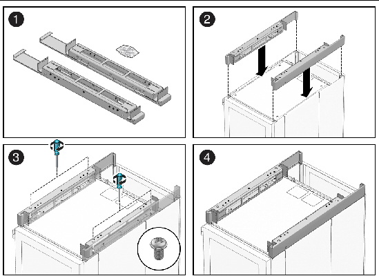
1. Unpack the contents of the expansion module kit (see panel 1).
The expansion module kit contains two expansion module mounting brackets and four M6 screws.
2. Place the brackets on the top of the Sun Blade 6048 cabinet (see panel 2).
The open part of the bracket should correspond with the opening in the back of the cabinet.
3. Use two of the M6 screws for each bracket to fasten the expansion module brackets (see panel 3).
a. Place two M6 screws in the two outermost screw holes of the right bracket.
b. Insert a screwdriver into the hole on top of the bracket that is directly above the screw, and tighten the screw.
c. Repeat steps a and b for the left bracket.
You can now mount a 2 rack unit (RU) system onto the expansion module, using the rack rails included with the system.
This section describes how to install floor tie downs onto the Sun Blade 6048 chassis.
| Note - This procedure describes a generic procedure for installing floor tie downs that are supplied by the customer. |
Refer to FIGURE 4-23 for the reference on the installation procedure.
FIGURE 4-23 Floor Tie Down Locations and Installation
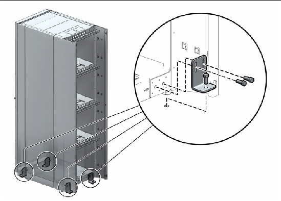
1. Remove the metal plates from the bottom shelf on the front and back of the system.
The brackets are installed in four places: two on the front, two on the back.
2. Install the four brackets in the in two outer holes on each side of the chassis front and back.
Refer to FIGURE 4-23 for locations where the brackets should be installed on the chassis.
3. Secure the bottom of the each bracket to the hole in the platform underneath the chassis
| Sun Blade 6048 Modular System Service Manual | 820-2863-13 |
Copyright © 2009 Sun Microsystems, Inc. All rights reserved.