| C H A P T E R 3 |
|
Preparing for Service |
This chapter contains information on preparing to service the Sun Blade 6048 modular system.
The following sections are in this chapter:
The Sun Blade 6048 modular system is designed for ease of use by both customers and authorized service personnel. All components in the Sun Blade 6048 modular system are removable and serviceable by a single person. Most components are customer-replaceable units (CRUs); however, some components are field-replaceable units (FRUs), which must be removed and installed only by authorized Sun service personnel. See Section 3.1.4, CRU Features and Section 3.1.5, FRU Features to determine which components are CRUs and which components are FRUs.
When a component fails, its associated amber Service Action Required LED indicator lights. See Section 3.1.2, Diagnosing and Detecting Component Faults.
The Sun Blade 6048 modular system is designed with a midplane to which various replaceable units are installed from the front and rear of the chassis.
Components that are hot-pluggable and hot-swappable do not require tools for removal or replacement. When you replace a component, an indicator light goes on or an audible click sounds so that you know the component is properly installed. For a list of hot-pluggable and hot-swappable components and those components that require the system or associated module to be powered off, see Section 3.1.3, Hot-Swappable and Hot-Pluggable Components.
You can use the CMM ILOM CLI interface or web interface to access information about some components installed in the chassis. In general, this applies to any component with a FRU ID, or present or not-present indicators. For more information about accessing component information, see the Sun Integrated Lights Out Manager 2.0 User’s Guide.
You can view the following component information:
Component information is accessible even when the component itself is powered off. When you remove or replace a component, the management interfaces report and log the change in the component inventory within 10 seconds.
The Sun Blade 6048 modular system uses fault-management software to monitor hardware health and to diagnose and report hardware failures on system components. When a sensor on the system chassis, power supplies, or fans registers a problem, the fault management software diagnoses the problem, and if it determines that a hardware failure has occurred, the software lights the component’s Service Action Required LED. The ILOM management interfaces are also updated to reflect the hardware failure, and the failure is recorded as a fault in the event log. For further information about the fault management software and how to monitor faults, see Chapter 2.
Within the Sun Blade 6048 modular system, most customer-replaceable units (CRUs) and field-replaceable units (FRUs) are hot-swappable, and some components are hot-pluggable. Both hot-swappable and hot-pluggable components can be removed and installed while the system is running, without affecting the rest of the system’s operations. However, for hot-pluggable components, you must prepare the operating system prior to the hot-plug procedure by performing certain system administration tasks.
The system continues to operate normally during a hot-swap or hot-plug operation of redundant components. However there are constraints as to the period of time you can perform removal and replacement of certain components. Refer to specific service procedures for that information.
CRUs are components that customers can replace on-site, without the assistance of authorized service personnel. The following table describes the components, and indicates whether they are hot-swappable or hot-pluggable.
FRUs are components that must be removed and replaced only by authorized Sun service personnel. These components are neither hot-swappable or hot-pluggable. The system must be powered off before you replace the components.
|
Installed from the front. You must remove all system modules, fan connector boards, and the midplane air baffle before you remove or install the midplane. |
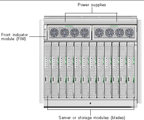
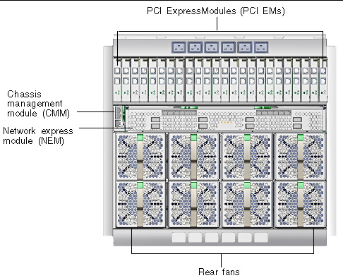
FIGURE 3-1 shows the front components and FIGURE 3-2 shows the rear components on the Sun Blade 6048 chassis. Internal components that are not visible in the illustrations are in the following locations:
FIGURE 3-1 Front View of Sun Blade Modular System Chassis

FIGURE 3-2 Rear View of Sun Blade Modular System Chassis

Although most components of the Sun Blade 6048 modular system can be removed while the system is powered on, you must remove power from the system to service the following components:
You can power off the system in one of two ways, as described in the following sections:
You can use the command-line interface to power off the system.
1. Log in to the ILOM CLI on the CMM.
2. Type the following command:
This command powers off the server without a graceful shutdown of the host operating systems.

|
Caution - Using the -foption could result in data loss unless the host operating systems have already been shut down at the server module level. |
For instructions on powering on the system after service is complete, see Section 4.4, Powering On the System After Service.
To powering off the system using the web interface:
1. Log in to the ILOM web interface on the chassis management module (CMM).
2. Select the CMM view from the left panel.
3. From the Remote Control tab, click the Remote Power Control tab.
4. Select the radio button next to /CH (chassis).
5. Use the drop-down list to select a new power state for the chassis.
The chassis current power state appears in the Current State column.
a. Select one of the following values:
Immediate Power Off: Select to power off the server without a graceful shutdown of the host operating systems. Using this option could result in data loss as the host operating systems are not powered off gracefully.
Graceful Shutdown and Power Off: Select to gracefully shut down the operating system before the host is powered off.
b. In the confirmation dialog box, click OK to confirm the change.
You will need the following tools and supplies to install the initial hardware into the Sun Blade 6048 modular system:
Use the following procedure to prevent static damage when you are accessing the server modules and server module options.
1. Use an antistatic mat or similar surface.
When installing an option onto the server module, such as a DIMM or disk drive, place those static-sensitive parts on an antistatic surface. You can use the following items as an antistatic surface:
2. Attach an antistatic wrist strap.
Attach one end of the wrist strap to the chassis sheet metal, and the other end to your wrist. Refer to the instructions that come with the strap.
3. Detach both ends of the strap when you are finished installing the parts.
Copyright © 2009 Sun Microsystems, Inc. All rights reserved.