
This chapter contains procedures for installing or replacing SIMMs and
NVSIMMs in the SPARCcenter 2000 system.
To halt the system safely:
1. Back up the system files and data, if necessary.
2. Notify users that the system is going down.
3. Halt the system using the appropriate commands.
4. Wait for the system-halted message and the boot monitor prompt.
5. Turn the key switch located on the front panel of the server to the
Standby position.
6. Turn the ac power switch on the system back panel off.
Caution -

The system chassis power must be turned off, and the ac power
cord must remain plugged in to ensure a proper ground.
Caution -

Use a cushioned ESD mat for these procedures. There are breakable
parts on the bottom of the system board.
1. Take off the rear screen by removing two Phillips screws, as shown in
Figure 3-1.
2. Unfasten and set aside any cables from the board backpanel.
Label any cables that are similar in appearance, to avoid confusion later.
3. Remove the two screws that secure the board to the card cage.
Set the screws aside for later use.
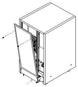
Figure 3-1
Rear Screen
4. Pull the curved ends of extraction levers outward to release the board
from the backplane connectors.
See Figure 3-2.
5. Place the board on a cushioned ESD mat.
Be careful not to flex the board while moving it.
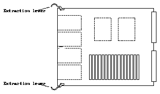
Figure 3-2
System Board Extraction Levers in the Unlocked Position
If replacing a faulty SIMM, see the location numbers (also known as
U-numbers or J-numbers) shown in Figure 3-3.
If you are adding SIMMs or NVSIMMs to the system, always add these devices
in multiples of eight. Also, be aware that your choice of location can affect the
efficient operation of these devices. For rules for selecting a location and for
optimizing memory use, see Section A.3, "SIMM and NVSIMM Locations for
SPARCcenter 2000 Systems," on page A-4.
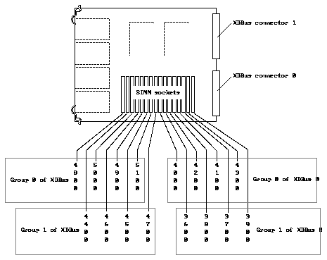
Figure 3-3
SIMM Location Numbers on the SPARCcenter 2000 Board
1. Locate the faulty SIMM by matching the location number displayed by
POST with the location numbers shown in Figure 3-3.
2. Orient the system board so that the XDBus(TM) connectors face you.
3. Unlock the SIMM by pressing the locking tabs toward the sides of the
socket and then tilting the SIMM forward, as shown in Figure 3-4.
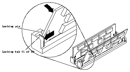
Figure 3-4
Unlocking a SIMM
4. For most SIMM sockets, there is very little space for movement, so unlock
two more SIMMs in front of the first SIMM, as shown in Figure 3-5.
This will allow the faulty SIMM to tilt forward far enough to disengage the
locking pins.
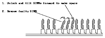
Figure 3-5
Creating Space to Remove a SIMM
5. For NVSIMM only:
-
To save data stored in the NVSIMM, do not move the battery jumper.
-
If the data is not worth saving, conserve battery power by moving the
battery jumper to the OFF position shown in Figure 3-6.
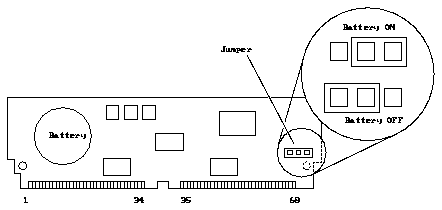
Figure 3-6
NVSIMM Jumper Location
6. Store or ship the SIMM or NVSIMM in an antistatic bag.
Note -
Do not mix SIMMs of different capacities in the same bank.
1. Orient the system board so that the XDBus connectors face you.
2. Remove the SIMM (or NVSIMM) from the antistatic package.
3. For NVSIMM only: if the battery is not already activated, move the
jumper to the ON position. See Figure 3-6. If the jumper is already in the
ON position, do not move it.
Caution -

Never move the jumper after the battery has been turned on, or data
contained in the NVSIMM will be lost.
4. Hold the SIMM at the edges, with pin 1 to your left.
The large alignment notch (see Figure 1-1) is at the left side.
5. Guide the SIMM into the slot so that the SIMM connector pads touch the
bottom of the socket.
Align the bottom alignment notch on the SIMM with the tab in the center of
the socket. The locking pins (see Figure 3-4) must align with the holes in the
sides of the SIMM.
6. Tilt the SIMM upright to lock it in place.
The locking tabs should automatically lock around the SIMM.
Note -
The SIMM should require very little insertion force. If there are
difficulties, the replacement SIMM may be backward. The alignment holes and
the alignment notch must align exactly with corresponding parts of the socket.
7. Lock back into place any SIMMs that were loosened in the SIMM
removal steps.
Note -
For help in selecting a card cage slot for a new system board, see
Appendix E, "General Rules for System Configuration."
1. Carefully insert the board in the proper slot in the card cage, ensuring
that the board does not slip out of the upper and lower card guides.
The component side of the board is to the right.
Caution -

Do not force the board into the slot. Components on either side of
the board may scrape against other boards. If the board binds, inspect the slot
for obstructions. Inspect both the board and the backplane for bent pins or
other damage.
2. Ensure that the extraction levers are in the outward position as you slide
the board toward the backplane connectors.
See Figure 3-2. The board will not seat fully unless the levers are in this
starting position.
3. Use the extraction levers to seat the board.
Swing both extraction levers simultaneously into the locked position. Do not
press on board to seat it - doing so will damage the connector pins.
4. Install two 2-56 Allen screws to secure the board to the card cage.
5. Connect any applicable interface cables to the system board backpanel.
1. Place the bottom of the rear screen on the flanges near the bottom of the
cabinet.
See Figure 3-1 on page 3-2.
2. Secure the screen in place with two screws.
To verify that the hardware was installed properly, run the POST program.
1. Turn on power to the terminal.
If the system does not have a terminal, connect an TTY terminal to serial
port A on the system master board and configure the terminal software. See
the instruction manual shipped with the terminal for configuration
instructions.
The most commonly-used set-up is:
Note -
The parameters listed above may differ from the customer site settings.
See the set-defaults and printenv commands in the manual, OpenBoot
Command Reference.
2. Turn the server key switch to the On or the Secure position to run POST
diagnostics.
Watch the diagnostics display for error messages. POST should finish in
approximately 60 seconds.
3. Watch the boot display to confirm that the system memory total includes
the newly installed memory modules.
4. After the system finishes booting, log in and resume normal operation.


