
1. Make sure you have determined the assigned SCSI addresses.
See Chapter 1, "Before You Start."
2. Make sure you have shut down the system.
See the appropriate handbook for your operating system.
3. Power off the computer system, monitor, Multi-Disk Pack, and all
peripherals connected to the computer system.
Make sure the power switch is in the off (O) position.
4. Detach the SCSI cable connecting the Multi-Disk Pack to the system.
5. Remove the SCSI terminator from the Multi-Disk Pack SCSI port.
6. Remove the lock block.
Use a Phillips screwdriver to unscrew the Phillips screw securing the lock
block. See Figure 4-1.
7. Lift the cover off.
See Figure 4-1.
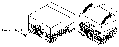
Figure 4-1
Removing the Multi-Disk Pack Cover
8. Make sure that the power cord is attached to the power outlet of the
Multi-Disk Pack and to the wall outlet.
9. Attach a wrist strap to your wrist and a metal part of the chassis.
See "Attaching the Wrist Strap" later in this chapter.
1. Unwrap the first two folds of the wrist strap. Wrap the adhesive side
firmly against your wrist. See Figure 4-2.
Figure 4-2
Attaching the Wrist Strap to Your Wrist
2. Peel the liner from the copper foil at the opposite end of the wrist strap.
3. Attach the copper end of the wrist strap to the top of the metal casing of
the power supply. See Figure 4-3.
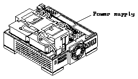
Figure 4-3
Location of Multi-Disk Pack Power Supply
1. Complete all steps in the section "Removing the Cover" in this chapter.
2. Unpack the disk drive.
See Chapter 1, "Before You Start." Make sure the disk drive is on the
antistatic bag the drive was shipped in.
3. Remove the SCSI ID jumpers (if installed) from the jumper block shown
in Figure 4-4.
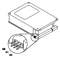
Figure 4-4
Removing the SCSI ID Jumpers on the Jumper Block by the Data Connector
of the Multi-Disk Pack
4. Remove the disk drive assembly from the unit. See the section
"Removing the Disk Drive Assembly" in this chapter.
5. Verify all disk drive SCSI ID jumper settings for the drives in the drive
assembly. See Figure 4-5.
6. Set the SCSI ID jumper settings on the disk drive to an unused SCSI
address.
See Figure 4-5. If you are running the SunOS 4.1.3 operating system (Solaris
1.1) or a later Solaris 1.x release, you can only use SCSI addresses 0, 1, 2,
or 3.
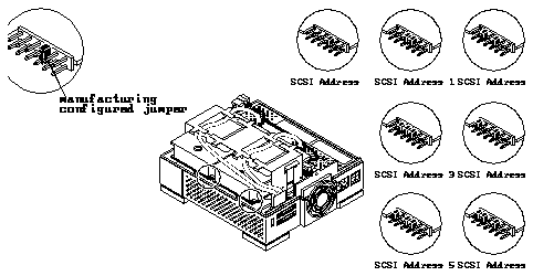
Figure 4-5
Setting the SCSI Address Jumpers in the Multi-Disk Pack
7. Make sure that the configuration jumpers match Figure 4-6.
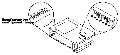
Figure 4-6
Configuration Jumper Settings for the Multi-Disk Pack
Table 4-1
Configuration Jumper Acronym Definitions
---------------------------------------


Acronym  Definition
---------------------------------------
SS       Reserved

DS       Delayed Start

ME       Motor Enable (Remote Spin-up)

WP       Write Protect

PE       Parity Enable

TE       Enable Terminators

TP       Term Power from Drive

TP       Term Power to SCSI Bus

---------------------------------------
1. Compete all steps in the sections "Removing the Cover," "Attaching the
Wrist Strap," and "Setting Jumpers" earlier in this chapter.
2. Disconnect the power supply cable connector from its mating disk drive
power connector.
To do so grab the adjoining connector firmly in one hand and with the other
hand pull the power cable connector from is mating connector. See
Figure 4-7.
3. Lift up on the metal handle of the SCSI connector clip and remove the
SCSI connector clip from the unit.
See Figure 4-7.
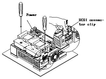
Figure 4-7
Removing the SCSI Connector Clip and Disconnecting the Power
Connector of the Multi-Disk Pack
4. Loosen the two captive Phillips-head screws on the bottom of the unit.
See Figure 4-7.
5. Lift the drive assembly up. Place the assembly on an antistatic mat.
See Figure 4-8 and Figure 4-9.
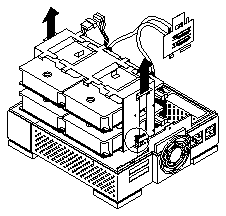
Figure 4-8
Removing the Drive Assembly of the Multi-Disk Pack
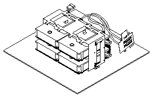
Figure 4-9
Multi-Disk Pack Disk Drive Assembly on an Antistatic Mat
1. Remove the disk drive assembly from the unit.
See the section "Removing the Disk Drive Assembly" in this chapter.
2. Remove the SCSI and power cables from the disk drive(s).
3. Remove the Phillips-head screws securing the disk drive to the assembly.
4. Carefully slide the drive out of the assembly.
5. Place the drive on an antistatic mat.
1. Compete all steps in the sections "Removing the Cover," "Attaching the
Wrist Strap," and "Setting Jumpers" earlier in this chapter.
2. If required for your configuration, install an SBus card with a SCSI host
adapter port on it into your computer system.
Follow the instructions that came with the SBus card or your computer
system documentation.
3. Attach the mounting plate to the disk drive.
See Figure 4-10.
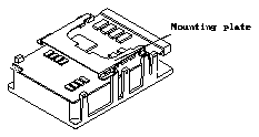
Figure 4-10
Disk Drive With Mounting Plate Attached for the Multi-Disk Pack
4. Make sure that the disk drive assembly is removed from the unit. See the
section "Replacing the Disk Drive Assembly," earlier in this chapter.
5. Slide the drive into the assembly.
The side with the disk drive controller board will face down and the data
and power connectors should face the power supply.
6. Connect the data and power connectors to the disk drive.
7. Insert the Phillips-head screws securing the drive to the assembly.
8. Replace the disk drive assembly into the unit.
See the section "Replacing the Disk Drive Assembly" which follows.
1. Move the power supply cable leading from the I/O bracket/fan out of
the unit.
2. Lower the drive assembly and rock it back and forth to make sure the
drive assembly sits properly.
3. Tighten the two captive screws on the bottom of the assembly.
You may have to shift the drive assembly back and forth until the holes are
aligned with the captive screws. See Figure 4-11.
Note -
Do not use a power screwdriver on a captive screw.
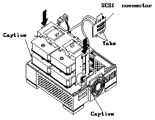
Figure 4-11
Lowering the Drive Assembly into the Multi-Disk Pack
4. Tuck the power supply cable leading from the fan into the unit.
5. Install the SCSI connector clip into the SCSI port area.
a. Lower the SCSI connector clip.
Align the two metal tabs at the bottom of the SCSI connector clip
between the plastic molded tabs on the lower SCSI port opening of the
unit. See Figure 4-12.
You should see both SCSI connectors in the SCSI connector openings on
the rear panel.
b. Hold the top of the SCSI connector clip and lift it up to lock it in place.
The hooks on the top of the SCSI connector clip will lock into place on
the rear of the unit.
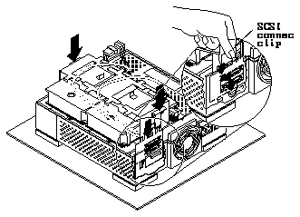
Figure 4-12
Inserting the SCSI Connector Clip into the Multi-Disk Pack
Note -
Make sure that the SCSI connector clip is completely and
securely inserted.
If it is loose, disconnect the power connector to the power supply and reinstall
the SCSI connector clip again. You may have to install the clip to a low
position in the opening then raise the clip slightly by lifting the clip and
hooking the tabs to attach to the unit and secure the clip.
6. Make sure that the SCSI cable is held in place by the two cable
management fingers on the top of the disk drive assembly.
See Figure 4-13.
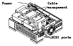
Figure 4-13
SCSI Cable Held in Place by Fingers on Multi-Disk Pack Disk Drive
Assembly
7. Connect the power connector.
See Figure 4-13. The connector is keyed.
1. Make sure all cables are inside of the unit.
2. Lower the cover on the front of the unit.
Gently lower the cover down until the cover closes completely. Press down
on all sides of the cover. See Figure 4-14.
Note -
Make sure that the hinge tab hooks on the front of the unit.
3. Attach the lock block.
Press down on the back of the cover above the fan with one hand. With the
other hand, insert the screw attaching the lock block to the chassis. Use a
Phillips screwdriver. See Figure 4-14.
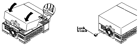
Figure 4-14
Replacing the Multi-Disk Pack Cover and Attaching the Lock Block
4. Reattach the SCSI cable and the regulated SCSI terminator (P/N 150-1785).
Note -
Make sure that a regulated SCSI terminator is attached to the last SCSI
device in the daisy-chain. A regulated SCSI terminator is stamped
"REGULATED".
5. Power on the computer system, the Multi-Disk Pack unit, and all other
peripherals connected to the computer system.
See the appropriate handbook for your operating system.
