Installing or Replacing Hardware
You can install or replace the following hardware in the Netra 150 server:
-
"Installing or Replacing the Tape Drive"--"Installing or Replacing the Tape Drive"
-
"Installing or Replacing Bay Disk Drives"--"Installing or Replacing Bay Disk Drives"
-
"Installing or Replacing SBus Cards"--"Installing or Replacing SBus Cards"
-
"Installing or Replacing DSIMMs"--"Installing or Replacing DSIMMs"
Installing or Replacing the Tape Drive
Take care not to damage the springfingers when installing or replacing the tape drive.
Note -
If you are replacing a faulty tape drive in the Netra 150 server, first go to "Removing the Tape Drive", then return here.
Installing the Tape Drive
-
Determine if you have the tape filler panel installed in place of the tape drive.
-
If the tape filler panel is installed, go to Step 2.
-
If the tape filler panel is not installed, go to Step 4.
-
-
If the tape filler panel is installed, remove the two phillips screws located on the bracket at the front of the tape filler panel.
-
Carefully slide the tape filler panel out of the front of the Netra 150 server.
-
Locate the SCSI target address dip switches at the bottom of the tape drive.
-
Set the jumpers to SCSI target ID 4.
Refer to the sticker underneath the tape drive to set the SCSI address to SCSI target ID 4.
-
Slide the mounting bracket down onto the tape drive.
-
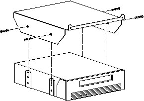
Install the four flat-head phillips screws to secure the mounting bracket to the tape drive (Figure 2-9).
Figure 2-9 Installing the Mounting Bracket on the Tape Drive
-
Connect the power and SCSI cables to the tape drive.
-
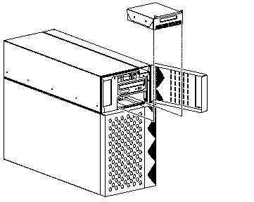
Carefully slide the tape drive into the Netra 150 server (Figure 2-10).
Figure 2-10 Installing the Tape Drive
-
Install the two phillips screws into the holes located on the top of the tape drive's front panel.
-
Go to "Finishing Up".
Removing the Tape Drive
-
Remove the two phillips screws located on the top of the tape drive's front panel.
-
Carefully slide the tape drive part way out of the front of the Netra 150's server (Figure 2-10).
-
Disconnect the power and SCSI cables from the rear of the tape drive.
-
Slide the tape drive the rest of the way out of the chassis.
-
Remove the four phillips screws securing the mounting bracket to the tape drive (Figure 2-9).
-
Slide the mounting bracket up and off the tape drive.
-
Place drive on an antistatic mat.
Installing or Replacing Bay Disk Drives
Note -
If you have the Netra NFS version of the Netra 150 server, you might have to suspend input before you can install or replace a drive. Refer to the Netra NFS SmartServe 1.1 User's Manual for more information.
Note -
If you are replacing a bay disk drive in the Netra 150 server, first go to "Removing the Bay Disk Drive", then return here.
Installing the Bay Disk Drive
-
Determine the proper location for the new bay disk drive.
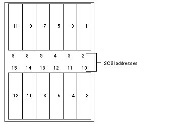
The bay disk drives should be installed from top-to-bottom, right-to-left, as shown in Figure 2-11. Figure 2-11 also shows the SCSI addresses for each drive. Note that you do not have to set the SCSI address on any of the disk drives installed in the internal disk bays because the SCSI addresses are set automatically when you install the drives in the bay.
Figure 2-11 Proper Ordering for Bay Disk Drives
-
Insert the disk drive into the drive bay, aligning the connector on the drive with the connector on the backplane.
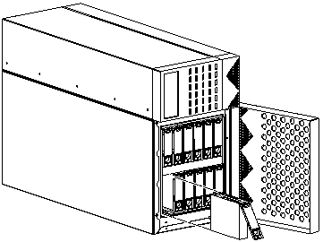
Keep the handle extended until you fully insert the drive (Figure 2-12).
Figure 2-12 Installing the Disk Drive into the Drive Bay
-
Gently push the drive in until it snaps onto the connector.
-
Swing the drive bracket handle closed until it latches.
-
Go to "Finishing Up".
Removing the Bay Disk Drive
Note -
If the disk you are replacing used to contain metadevice state replicas, you may want to clear the replica from the disk before replacing it. Refer to the Netra User's Manual for more details.
-
Unlatch the drive bracket handle (on the bottom) to release it.
-
Pull the bracket handle out and swing it open 180 degrees until it makes contact with the chassis.
Note -If you are removing a hard drive from the top of the chassis, then you will not be able to swing the bracket handle 180 degrees. Swing the bracket up and gently pull the drive out of the chassis.
-
Continue pushing the handle onto the chassis, applying mild pressure until the drive pops out from the connector.
-
Slide the drive out and set it on an antistatic mat.
Installing or Replacing SBus Cards
Note -
If you are replacing an SBus card in the Netra 150 server, first go to "Removing an SBus Card ", then return here.
Installing an SBus Card
-
Place the SBus card on an antistatic surface.
-
If required, set the jumpers or switches on the card.
See your SBus product documentation.
-
Remove the SBus card extractor (if any).
-
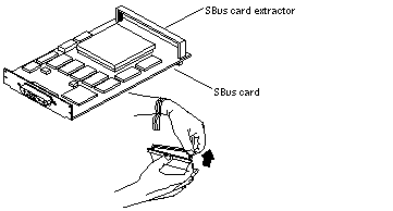
Bend one leg of the extractor slightly to the outside until the hook clears the hole in the SBus card (Figure 2-13).
-
Remove the other side of the extractor.
It should come out easily without being bent.
Figure 2-13 Removing the SBus Card Extractor
-
-
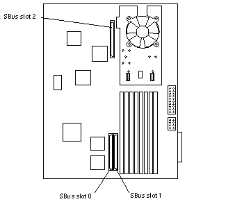
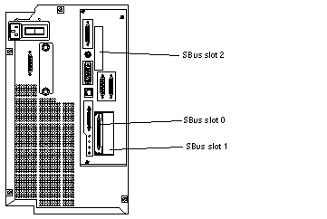
Locate the SBus slot in which you want to install the card.
The Netra 150 system board has three SBus slots. See Figure 2-14 for the location of each SBus slot.
Figure 2-14 SBus Slots Location
-
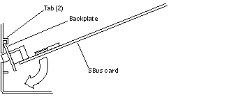
Slide the card at an angle into the system unit by hooking the card backplate under the two tabs on the back panel (Figure 2-15).
Be sure the card backplate shows through the slot on the back panel.
Figure 2-15 Replacing the SBus Card
-
Align the connector with the SBus socket. Gently press the corners of the card to push the connector into the socket.
Do not force the card, or you may damage the pins on the card. If the SBus card is located in SBus slot 0 or 1, see Figure 2-16. If the SBus card is located in SBus slot 2, see Figure 2-17.
-
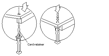
Lock the card retainers.
-
If the SBus card is located in SBus slot 0 or 1, push the rear card retainers forward over the edge of the SBus card. See Figure 2-16.
-
If the SBus card is located in SBus slot 2, push the card retainer down.
See Figure 2-17. There is only one card retainer for the SBus slot 2.
Figure 2-16 Lock in the SBus Card Retainers, SBus Slots 0 or 1
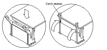
Figure 2-17 Lock in the SBus Card Retainer, SBus Slot 2
-
-
Locate the SBus card at the rear of the Netra 150 server.
-
Go to "Finishing Up".
Removing an SBus Card
-
Locate the SBus card that you want to remove on the back panel of the system board.
The SBus card will be installed in one of the three SBus slots in the system board (Figure 2-18).
Note -If the defective SBus card is located in slot 0, and there is another SBus card installed in slot 1, you must remove the card from slot 1 before removing the defective card from slot 0.
Figure 2-18 Locating the SBus Slots
-
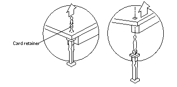
Locate the SBus card on the system board inside the Netra 150 server and unlock the card retainers.
-
If the SBus card is located in SBus slot 0 or 1, push the card retainers back from the edge of the SBus card. See Figure 2-19.
-
If the SBus card is located in SBus slot 2, pull the card retainer up. See Figure 2-20. There is only one card retainer for the SBus slot 2.
Figure 2-19 Removing an SBus Card from Slot 0 or 1
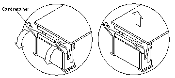
Figure 2-20 Removing an SBus Card from Slot 2
-
-
Grasp the SBus card at both corners, and pull it up to disconnect it from the socket.
 Caution -
 Avoid applying force to one end or one side of the board. It damages the connector pins.
-
Slide the SBus card out of the back panel, and place it on an antistatic surface.
Installing or Replacing DSIMMs
DSIMMs are made of electronic components that are extremely sensitive to static electricity. Ordinary mounts of static from your clothes or work environment can destroy the modules. Do not remove any DSIMM from the anti-static container until you are ready to install it on the system board. Handle the modules only by the edges. Do not touch the components or any metal parts. Always wear a grounding strap when you handle the modules.
Note -
Each DSIMM removed from the system should be replaced with another DSIMM. The replacement DSIMM should have the same capacity as the defective one. It should also be inserted into the same socket as the defective one.
The Netra 150 system board must have a pair of DSIMMs in bank 0 to be able to boot. Up to eight DSIMMs can be installed in the system. They can be located in the sockets described on Table 2-2. However, each bank must contain two DSIMMs of equal density (for example: two 16MB DSIMMs, two 64MB DSIMMs) to function properly. Do not mix DSIMM densities in any bank.
Table 2-2 Bank and Socket Locations for DSIMMs| Bank | Socket |
|---|---|
| 0 (required) | U0701 + U0601 |
| 1 | U0702 + U0602 |
| 2 | U0703 + U0603 |
| 3 | U0704 + U0604 |
Note -
If you are replacing a DSIMM in the Netra 150 server, go first to "Removing a DSIMM ", then return here.
Installing a DSIMM
-
Take the replacement DSIMM from the antistatic container.
-
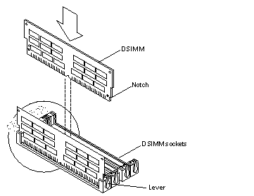
Position the DSIMM in the socket so the notch is on the same side as the lever (Figure 2-21).
Note -The replacement DSIMM should have the same capacity as the defective DSIMM.
-
Insert the DSIMM into the socket by pushing it down at both ends until it is fully seated in the socket (Figure 2-21).
Figure 2-21 Replacing a DSIMM
-
Go to "Finishing Up".
Removing a DSIMM
-
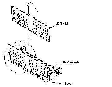
Locate the DSIMM that you want to remove on the system board (Figure 2-22).
Figure 2-22 Removing a DSIMM
-
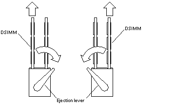
Push the lever away from the DSIMM (Figure 2-23).
Figure 2-23 DSIMM Ejection Lever
-
Pull the DSIMM out of the socket.
- © 2010, Oracle Corporation and/or its affiliates
