Installing or Replacing DSIMMs
DSIMMs are made of electronic components that are extremely sensitive to static electricity. Ordinary mounts of static from your clothes or work environment can destroy the modules. Do not remove any DSIMM from the anti-static container until you are ready to install it on the system board. Handle the modules only by the edges. Do not touch the components or any metal parts. Always wear a grounding strap when you handle the modules.
Note -
Each DSIMM removed from the system should be replaced with another DSIMM. The replacement DSIMM should have the same capacity as the defective one. It should also be inserted into the same socket as the defective one.
The Netra 150 system board must have a pair of DSIMMs in bank 0 to be able to boot. Up to eight DSIMMs can be installed in the system. They can be located in the sockets described on Table 2-2. However, each bank must contain two DSIMMs of equal density (for example: two 16MB DSIMMs, two 64MB DSIMMs) to function properly. Do not mix DSIMM densities in any bank.
Table 2-2 Bank and Socket Locations for DSIMMs| Bank | Socket |
|---|---|
| 0 (required) | U0701 + U0601 |
| 1 | U0702 + U0602 |
| 2 | U0703 + U0603 |
| 3 | U0704 + U0604 |
Note -
If you are replacing a DSIMM in the Netra 150 server, go first to "Removing a DSIMM ", then return here.
Installing a DSIMM
-
Take the replacement DSIMM from the antistatic container.
-
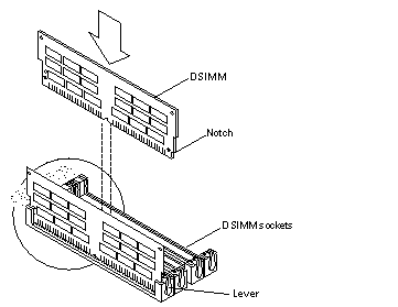
Position the DSIMM in the socket so the notch is on the same side as the lever (Figure 2-21).
Note -The replacement DSIMM should have the same capacity as the defective DSIMM.
-
Insert the DSIMM into the socket by pushing it down at both ends until it is fully seated in the socket (Figure 2-21).
Figure 2-21 Replacing a DSIMM

-
Go to "Finishing Up".
Removing a DSIMM
-
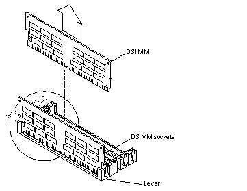
Locate the DSIMM that you want to remove on the system board (Figure 2-22).
Figure 2-22 Removing a DSIMM

-
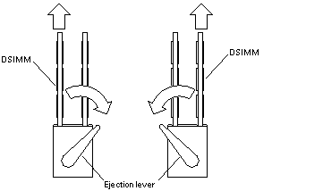
Push the lever away from the DSIMM (Figure 2-23).
Figure 2-23 DSIMM Ejection Lever

-
Pull the DSIMM out of the socket.
- © 2010, Oracle Corporation and/or its affiliates
