Replacing Foam Piece 1 and the Left Panels
-
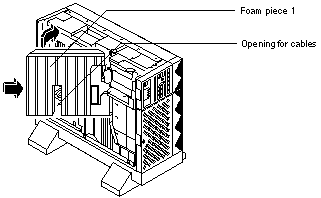
Insert the right side of Foam Piece 1 into its proper location (Figure 2-25).
Fit Foam Piece 1 behind the system disk connectors. Be careful not to dislodge the connectors.
Figure 2-25 Replacing Foam Piece 1

-
Rotate the left side of the foam piece into place in the server.
Be careful not to disturb the surrounding assemblies and cables.
-
If necessary, fit the power cables in the opening located in the center of Foam Piece 1 (Figure 2-25).
-
Slide the bottom of the left inner panel into the groove at the top of the Netra 150 server and tilt the panel inward onto the chassis.
-
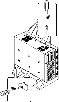
With the Phillips #1 screwdriver, tighten the eight Phillips-head captive screws at the side and top of the left inner panel (Figure 2-26).
The screw at the top front portion of the panel does not attach to anything.
Figure 2-26 Installing the Left Inner Panel

-
Press the left outer panel against the left side of the Netra 150 server and slide the panel forward until it stops.
-
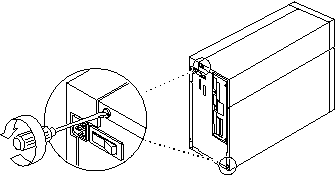
Tighten the two Phillips-head captive screws at the rear of the Netra 150 server (Figure 2-27).
Figure 2-27 Installing the Left Outer Panel

- © 2010, Oracle Corporation and/or its affiliates
