| Skip Navigation Links | |
| Exit Print View | |

|
Writing Device Drivers Oracle Solaris 11 Express 11/10 |
| Skip Navigation Links | |
| Exit Print View | |

|
Writing Device Drivers Oracle Solaris 11 Express 11/10 |
Part I Designing Device Drivers for the Oracle Solaris Platform
1. Overview of Oracle Solaris Device Drivers
2. Oracle Solaris Kernel and Device Tree
5. Managing Events and Queueing Tasks
7. Device Access: Programmed I/O
10. Mapping Device and Kernel Memory
Multiple Power Management Components
Automatic Power Management for Devices
Device Power Management Interfaces
Device Power State Transitions
Automatic Power Management for Systems
Entry Points Used by System Power Management
Power Management Device Access Example
Changes to Power Management Interfaces
13. Hardening Oracle Solaris Drivers
14. Layered Driver Interface (LDI)
Part II Designing Specific Kinds of Device Drivers
15. Drivers for Character Devices
18. SCSI Host Bus Adapter Drivers
19. Drivers for Network Devices
Part III Building a Device Driver
21. Compiling, Loading, Packaging, and Testing Drivers
22. Debugging, Testing, and Tuning Device Drivers
23. Recommended Coding Practices
B. Summary of Oracle Solaris DDI/DKI Services
C. Making a Device Driver 64-Bit Ready
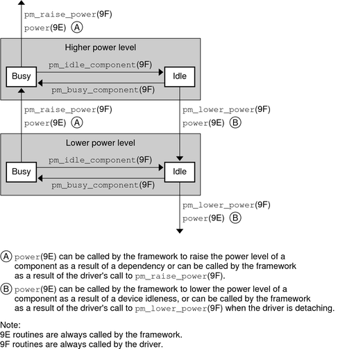
Figure 12-1 illustrates the flow of control in the power management framework.
When a component's activity is complete, a driver can call pm_idle_component(9F) to mark the component as idle. When the component has been idle for its threshold time, the framework can lower the power of the component to its next lower level. The framework calls the power(9E) function to set the component's power to the next lower supported power level, if a lower level exists. The driver's power(9E) function should reject any attempt to lower the power level of a component when that component is busy. The power(9E) function should save any state that could be lost in a transition to a lower level prior to making that transition.
When the component is needed at a higher level, the driver calls pm_busy_component(9F). This call keeps the framework from lowering the power still further and then calls pm_raise_power(9F) on the component. The framework next calls power(9E) to raise the power of the component before the call to pm_raise_power(9F) returns. The driver's power(9E) code must restore any state that was lost in the lower level but that is needed in the higher level.
When a driver is detaching, the driver should call pm_lower_power(9F) for each component to lower its power to its lowest level. The framework can then call the driver's power(9E) routine to lower the power of the component before the call to pm_lower_power(9F) returns.
Figure 12-1 Power Management Conceptual State Diagram
