| Skip Navigation Links | |
| Exit Print View | |

|
Sun Server X2-4 (formerly Sun Fire X4470 M2) Service Manual |
1. Sun Server X2-4 Service Manual Overview
1.2 Server Front Panel Features
1.3 Server Back Panel Features
1.4 Performing Service Related Tasks
2. Preparing to Service the Sun Server X2-4
2.1 Location of Replaceable Components
2.2 Tools and Equipment Needed
2.3 Performing Electrostatic Discharge and Static Prevention Measures
2.3.1 Using an Antistatic Wrist Strap
2.4 Positioning the Server for Maintenance
Extend the Server to the Maintenance Position
2.5 Releasing the Cable Management Arm
Power Off the Server Using the Service Processor Command-Line Interface
2.7 Removing the Server Top Cover
2.8 Removing or Installing Filler Panels
2.9 Attaching Devices to the Server
3. Servicing CRU Components That Do Not Require Server Power Off
3.1 Servicing Disk Drives (CRU)
3.1.1 Disk Drive Status LED Reference
3.1.2 Removing and Installing Disk Drives and Disk Drive Filler Panels
Remove a Disk Drive Filler Panel
Install a Disk Drive Filler Panel
3.2 Servicing Fan Modules (CRU)
3.2.2 Fan Module LED Reference
3.2.3 Detecting Fan Module Failure
3.2.4 Removing and Installing Fan Modules
3.3 Servicing Power Supplies (CRU)
3.3.1 Power Supply LED Reference
3.3.2 Detecting a Power Supply Failure
3.3.3 Removing and Installing Power Supplies
4. Servicing CRU Components That Require Server Power Off
4.1 Servicing Memory Risers and DIMMs (CRU)
4.1.1 CPUs, Memory Risers, and DIMMs Physical Layout
4.1.2 Memory Riser Population Rules
4.1.3 Memory Riser DIMM Population Rules
4.1.4 Memory Performance Guidelines
4.1.8 Removing and Installing Memory Risers, DIMMs, and Filler Panels
Remove a Memory Riser Filler Panel
Remove a Memory Riser and DIMM
Install Memory Risers and DIMMs
Install a Memory Riser Filler Panel
4.2 Servicing PCIe Cards (CRU)
4.2.1 PCIe Card Configuration Rules
4.2.2 PCIe Cards With Bootable Devices
4.2.3 Avoiding PCI Resource Exhaustion Errors
4.2.4 Removing and Installing PCIe Cards and PCIe Card Filler Panels
Remove a PCIe Card Filler Panel
Install a PCIe Card Filler Panel
4.3 Servicing the DVD Drive and DVD Driver Filler Panel (CRU)
Remove the DVD Drive or DVD Drive Filler Panel
Install the DVD Drive or DVD Drive Filler Panel
4.4 Servicing the System Lithium Battery (CRU)
5.1 Servicing the CPU and Heatsink (FRU)
5.1.2 Removing and Installing a Heatsink Filler Panel, CPU Cover Plate, Heatsink, and CPU
5.2 Servicing the Fan Board (FRU)
5.3 Servicing the Power Supply Backplane (FRU)
Remove the Power Supply Backplane
Install the Power Supply Backplane
5.4 Servicing the Disk Drive Backplane (FRU)
Remove the Disk Drive Backplane
Install the Disk Drive Backplane
5.5 Servicing the Motherboard (FRU)
6. Returning the Server to Operation
6.1 Replacing the Server Top Cover
6.2 Returning the Server to the Normal Rack Position
Return the Server to the Normal Rack Position
7. Servicing the Server at Boot Time
7.3 Default BIOS Power-On Self-Test (POST) Events
7.4 BIOS POST F1 and F2 Errors
7.5 How BIOS POST Memory Testing Works
7.6 Ethernet Port Device and Driver Naming
7.6.1 Ethernet Port Booting Priority
7.8 Performing Common BIOS Procedures
7.8.1 Configuring Serial Port Sharing
8. Troubleshooting the Server and ILOM Defaults
8.1 Troubleshooting the Server
8.2.1 Diagnostic Tool Documentation
8.3 Using the Preboot Menu Utility
8.3.1 Accessing the Preboot Menu
8.3.2 Restoring Oracle ILOM to Default Settings
8.3.3 Restoring Oracle ILOM Access to the Serial Console
8.3.4 Restoring the SP Firmware Image
8.3.5 Preboot Menu Command Summary
8.5 Locating the Chassis Serial Number
A.3 Environmental Requirements
B.2 BIOS Advanced Menu Selections
B.3 BIOS PCIPnP Menu Selections
B.5 BIOS Security Menu Selections
B.6 BIOS IO/MMIO Menu Selections
B.7 BIOS Chipset Menu Selections
C.3 Gigabit-Ethernet Connectors
C.4 Network Management Port Connector
C.6 Serial Attached SCSI (SAS) Connector
D. Getting Server Firmware and Software
D.1 Firmware and Software Updates
D.2 Firmware and Software Access Options
D.3 Available Software Release Packages
D.4 Accessing Firmware and Software
Download Firmware and Software Using My Oracle Support
D.4.1 Requesting Physical Media
D.4.2 Gathering Information for the Physical Media Request
Oracle's Sun Server X2-4 is a 3 rack unit (RU) rackmount server that uses the Intel Xeon E7 platform. This section describes the major features, components, and capabilities of the server.
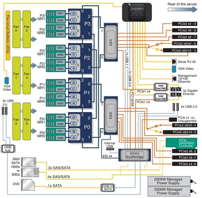
The Intel Xeon E7 platform is based on the Intel Xeon Processor E7-4800 Series and uses the Intel 7500 Chipset I/O hub (IOH) as its primary chipset. The platform uses the Intel QuickPath Interface (QPI), a high-speed, differentially signaled, point-to-point interface that forms a communication fabric among the processors (CPUs) and IOHs in the system.
The Sun Server X2-4 uses two Intel 7500 Chipset I/O hubs, each connected to two of the four CPUs. One of these I/O hubs is designated the legacy I/O hub and has a connection to the Intel I/O Controller Hub 10 (ICH10) southbridge component.
Four CPU Block Diagram shows a block diagram for a Sun Server X2-4 with four CPUs.
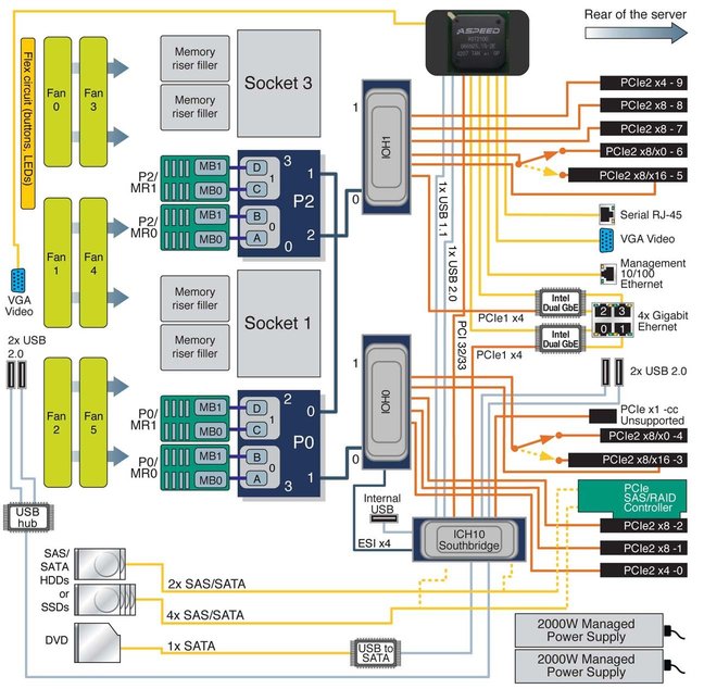
Two CPU Block Diagram shows a block diagram for a Sun Server X2-4 with two CPUs.
Note - In the diagrams, the PCIe SAS/RAID Controller is shown as installed in Slot 2. If a particular SAS/RAID Controller has specific cooling requirements, it might have to be installed in Slot 4. For information about cooling requirements, refer to the Sun Server X2-4 Product Notes.
Figure 1-1 Four CPU Block Diagram

Figure 1-2 Two CPU Block Diagram

The Sun Server X2-4 supports two or four processors (CPUs), as shown in Four CPU Block Diagram and Two CPU Block Diagram. The two-CPU configuration must have CPUs (with heatsinks) in sockets 0 and 2 and heatsink filler panels installed in sockets 1 and 3.
In a two-CPU configuration, all three QPI interconnects and both CPUs must be operational. The four-CPU configuration offers a greater level of resiliency with redundant QPI interconnects that allow working CPUs to route around a disabled CPU as the system starts.
Features of each Intel Xeon Processor E7-4800 Series include:
Up to ten cores with Hyper-Threading (two threads/core)
Up to 30MB shared last level cache
32nm process technology
Two integrated memory controllers with four Intel Scalable Memory Interconnects (SMI channels)
Supports speeds of DDR3-1067 MT/s via an Intel 7510 Scalable Memory Buffer
Four full-width, bidirectional Intel QuickPath interconnects (QPI links)
6.4 GT/s (12.8 GB/s per direction)
Automatic self-healing by degrading to half-width or quarter-width link operation
CPU Thermal Design Power (TDP) of 105W or 130W
Note - For more information about Intel QuickPath Interconnects, refer to Weaving High Performance Multiprocessor Fabric from Intel Press at http://www.intel.com/intelpress/sum_qpi.htm.
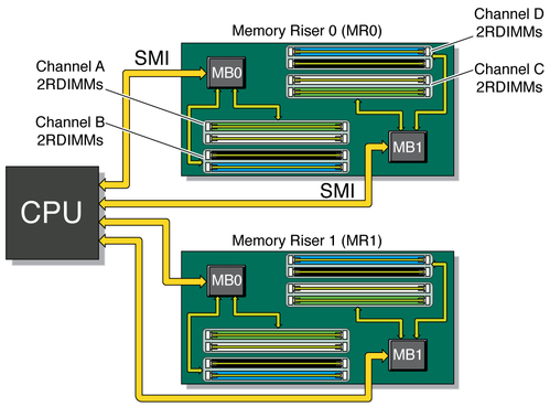
Each CPU in the Sun Server X2-4 has four SMI channels leading to Intel 7510 Scalable Memory Buffers (located on two memory risers). Each memory buffer has an SMI link to the CPU and two DDR3 interfaces. Each SMI interface can operate at speeds of 6.4 GT/s, which correspond to DDR3 operation at 1067 MT/s. From the CPU to the Intel 7510 Scalable Memory Buffer, the SMI interface supports 11 lanes (9 data + 1 CRC + 1 spare). From the Intel 7510 Scalable Memory Buffer to the CPU, the SMI interface supports 14 lanes (12 data + 1 CRC + 1 spare). The CPU retries memory transactions that incur a CRC error. For persistent errors, the SMI link has spare lanes for automatic self-healing.
The system supports a maximum of eight memory risers (4 CPU configuration) or four memory risers (2 CPU configuration). Each riser houses 8 DIMM slots for the four DDR3 channels. The system can operate with 0, 2, 4, 6 or 8 DIMMs on a given riser. For maximum performance, install at least two ranks of DIMMs on every available DDR3 channel (for example, 4 DIMMs per riser with two risers per CPU).Each of two memory controllers in a CPU operates its two SMI channels as a lock-step pair. The memory controller treats each pair of DDR3 channels behind the two memory buffers as a 144-bit-wide DRAM interface. As a result, the DIMMs must be installed in pairs, with identical DIMMs in each pair.
The DDR3 interfaces include the following features:
Accommodates x4 and x8 Single-Rank, Dual-Rank, Quad-Rank RDIMMs
Supports up to 2 RDIMMs per DDR3 channel (8 DIMM slots per memory riser)
DDR3 speed: 1067 MT/s or 978 MT/s (dictated by SMI speeds of CPUs)
DRAM Technology: 2 or 4 Gb die, 1.35-volt or 1.5-volt operation
DIMM Capacity: 4, 8, 16 GB (16 GB with Quad-Rank DIMMs only)
Currently supported DIMMs are PC3L RDIMMs, dual-rank in 4-, 8-, and quad-rank 16-GB sizes
For more information about CPUs, memory risers, and memory layout, including guidelines for populating memory risers and DIMMs, see 4.1 Servicing Memory Risers and DIMMs (CRU).
Memory Architecture shows the architecture of the server memory.
Figure 1-3 Memory Architecture

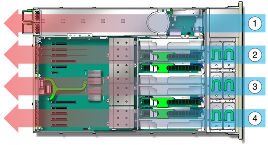
The Sun Server X2-4 is cooled from front to back. Cooling occurs in two areas of the chassis, separated by a plastic dividing wall. In the power supply cooling zone, fans at the back of the power supplies cool the drive bays as well as the power supplies, by drawing air into the depressurized zone at the right of the chassis. In the main cooling zones, six 92-mm high-performance fans, arranged in two rows for redundancy, cool the motherboard, memory risers, and I/O cards. The motherboard is divided into three zones and each pair of fans is separately regulated to cool that zone. Since the main cooling zones are pressurized, it is important to maintain the seal of the dividing wall so that the power supply units can draw air through the drive bay.
The unrestricted airflow over the motherboard minimizes system noise. Dividing the cooling into zones allows for greater use of system resources, since each zone can operate independently at its highest efficiency.
Server Cooling Zones shows the cooling zones.
Figure 1-4 Server Cooling Zones

Figure Legend
1 Power supply cooling zone
2 Chassis cooling zone 2
3 Chassis cooling zone 1
4 Chassis cooling zone 0
For internal storage, the server chassis provides:
Six 2.5-inch drive bays, accessible through the front panel. The supported drive interfaces for each bay depend on the host bus adapter (HBA) chosen.
An optional slot-loading DVD+/-RW drive on front of the server, below the drive bays. This SATA DVD connects to a USB-SATA bridge, so that is appears to the system software as a USB storage device.
One internal high-speed USB port on the motherboard. This port can hold a USB flash device for system booting.
In addition, the service processor can present virtual USB storage devices to the system.The ICH10 southbridge on the motherboard provides six built-in SATA2 (3-Gbit/s) ports, accessible through two SAS4I connectors (Port 0-3 and Port 4-5). When configured with any 2.5-inch SAS drives, the system must be equipped with one PCI Express (PCIe) Gen-2 internal HBA card to support the front 2.5-inch drive bays.Each offered PCIe Gen-2 HBA has 8 SAS2/SATA2 internal ports accessible through two SAS4I connectors (Port 0-3 and Port 4-7). Since the drive cage has only six bays, Port 6-7 of an internal HBA are not used in this system.
With an internal SAS-2 HBA card installed in a PCIe slot, the six bays can handle any combination of supported SAS and SATA hard disk drives (HDDs) and solid-state drives (SSDs). If the disk backplane is connected to the built-in ICH10 SATA-2 controller rather than an HBA card, only SATA storage devices will operate. (When a RAID volume is configured on the HBA card, the drive bays for the RAID members must hold the same type of storage device.)
The following table summarizes the components and capabilities of the Sun Server X2-4.
Table 1-1 Sun Server X2-4 Components and Capabilities
|