Creating the InventoryService BPEL Process
The HTTP-SOAP-PO-BPEL project utilizes two BPEL processes, InventoryService.bpel, which creates a response message
with the status of the inventory, and POService.bpel, which creates the purchase order
response.
For this example the BPEL Designer's Design view and the BPEL Mapper are
used to create the BPEL process.
For more information about using the BPEL Designer, see Developer Guide to BPEL Designer.
To create the InventoryService BPEL process
- From the Project window, right-click the HTTP-SOAP-PO-BPEL project's Process Files directory and select
New -> BPEL Process from the pop-up menu. The New BPEL Process wizard appears displaying the
Name and Location page.
- From the New BPEL Process wizard, enter InventoryService for the File Name.
- Click Finish. The BPEL Designer appears containing the new BPEL process.
To Create the InventoryService business process using the BPEL Designer
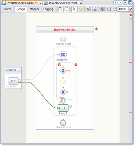
- From the Project window, double-click InventoryService.bpel , under the project's Process Files directory. The
Design view of the InOutMapper.bpel is displayed graphically in the IDE's BPEL Designer.
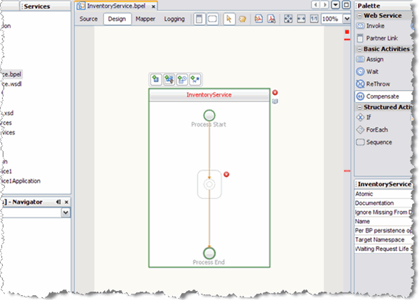
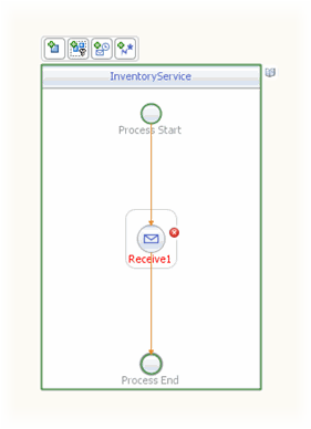
- Add a Receive element to the process flow. To do this, drag-and-drop the
Receive element from the BPEL Designer Palette to the link between the Process
Start and Process End in the designer's process flow.
The IDE provides you with visual clues to show you where you can
drop the selection. The Receive element is added to the Design view.
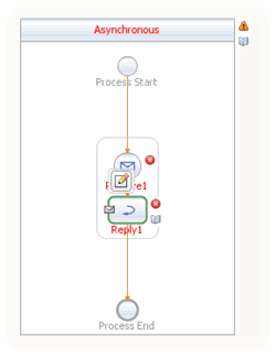
- Add a Reply element to the process flow between the Receive1 element and
the Process End.
The IDE provides you with visual clues to show you where you can
drop the selection. The Reply1 web service is added to the process flow.
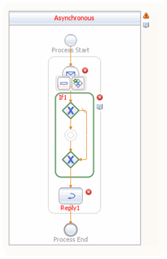
- Add an If activity to the process flow diagram between the Receive1 and
Reply1 elements. To do this, drag-and-drop the If element from the BPEL Designer
Palette to the link between the Receive1 and Reply1 elements in the
InventoryService process flow.
- Create a new Partner Link by dragging and dropping the InventoryService.wsdl file from
the Projects window to the left side of the BPEL Designer canvas. The
IDE provides you with visual clues to show you where you can drop
the selection. The PartnerLink1 partner link is added to left side of the
BPEL Designer canvas.
- Set the Receive1 element Partner Link to PartnerLink1 as follows:
- From the BPEL Designer's Design view, double-click the Receive1 element. The Receive1
[Receive] - Property Editor appears.
- From the property editor, select PartnerLink1 as the Partner Link value.
- Click the Input Variable field's Create button. The New Input Variable dialog box
appears. Click OK to create the new input variable.
- Click OK. A partner link is now displayed between the PartnerLink1 and the
Receive1 element in the Design view.
- Set the Reply1 element Partner Link to PartnerLink1 as follows:
- From the BPEL Designer's Design view, click the Reply1 element and click
the Reply1 Edit button. The Reply1 [Reply] - Property Editor appears.
- From the property editor, select PartnerLink1 as the Partner Link value.
- Click the Output Variable field's Create button. The New Output Variable dialog box
appears. Click OK to create the new output variable.
- Click OK. A partner link is now displayed between the PartnerLink1 and the
Reply1 element in the Design view.
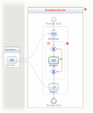
- Add an Assign element to the If1 element in the process
flow. To do this, drag-and-drop the Assign activity from the BPEL Designer Palette to
the link between the beginning and ending node of the If1 element. The
Assign1 element is added to the InventoryService process flow.
To specify the business logic for the InventoryService BPEL process
- Specify the business logic for the If1 element (not the Assign1 element) from
the BPEL Mapper as follows:
- Select the If1 element in the BPEL Designer's Design view, and click
the Designer's Mapper button to open the BPEL Mapper.
The If1 activity is displayed in the BPEL Mapper window.
- From the BPEL Mapper, expand the nodes in the Output pane.
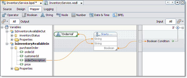
- From the BPEL Mapper toolbar's String menu, select Starts With. The Starts With
function box appears in the Mapping pane.
- Map the orderDescription node, under Variables -> IsInventoryAvailableIn -> purchaseOrder in the Output pane of the
BPEL Mapper, to the first inbound String node of the Starts With
function box. To do this, click on the orderDescription node, and drag your
cursor to the String node of the Starts With function box. A link now joins
the two nodes.
- From the BPEL Mapper toolbar's String menu, select String Literal. A String
Literal function box appears in the Mapping pane. Enter OrderVal, as the String Literal
value.
- Map the outbound OrderVal node of the String Literal function box to the
inbound string2 node of the Starts With function box.
- Map the outbound Boolean node of the Starts With function box to the
Boolean Condition node, under If1 in the Input pane of the BPEL Mapper.
- Specify the business logic for the Assign1 element from the BPEL Mapper as
follows:
- From the BPEL Designer's Design view, select the Assign1 element and click
the Mapper button to open the BPEL Mapper.
The Assign1 activity is displayed in the BPEL Mapper window.
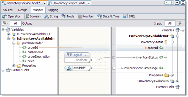
- Map orderId, under Variables -> IsInventoryAvailableIn -> purchaseOrder in the Output pane of the BPEL Mapper, to
orderId, under Variables -> IsInventoryAvailableOut -> inventoryStatus in the Input pane of the BPEL Mapper.
- From the BPEL Mapper toolbar's Boolean menu, select and drag Logical True to the
Mapping pane. Map the outbound Boolean node of the Logical True function box to
inventoryStatus under Variables -> IsInventoryAvailableOut -> inventoryStatus in the Input pane of the
BPEL Mapper.
- From the BPEL Mapper toolbar's String menu, select String Literal. A String
Literal function box appears in the Mapping pane. Enter available, as the String Literal
value.
- Map the outbound available node of the String Literal function box to inventoryStatusMessage,
under Variables -> IsInventoryAvailableOut -> inventoryStatus in the Input pane of the BPEL Mapper.
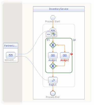
- Add an Assign element to the Else of the If1 element
in the process flow. To do this, drag-and-drop the Assign activity from the BPEL
Designer Palette to the center of the ELSE branch of the If1
element. The Assign2 element is added to the InventoryService process flow.
- Specify the business logic for the Assign2 element from the BPEL Mapper
as follows:
- Select the Assign2 element in the BPEL Designer's Design view, and click the
Designer's Mapper button to open the BPEL Mapper.
The Assign2 activity is displayed in the BPEL Mapper window.
- From the BPEL Mapper, expand the nodes in the Output and Input panes.
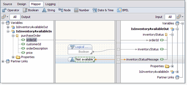
- Map orderId, under Variables -> IsInventoryAvailableIn -> purchaseOrder in the Output pane of the BPEL Mapper, to
orderId, under Variables -> IsInventoryAvailableOut -> inventoryStatus in the Input pane of the BPEL Mapper.
- From the BPEL Mapper toolbar's Boolean menu, drag Logical Falseto the center
pane of the Designer, inline with the inventoryStatus node under Variables ->
IsInventoryAvailableOut -> inventoryStatus in the Input pane of the BPEL Mapper.
The Logical False function box appears in the Mapping pane.
- Map the outbound Boolean node of the Logical False function box, to the
inventoryStatus node under Variables -> IsInventoryAvailableOut -> inventoryStatus in the Input pane of the
BPEL Mapper.
- From the BPEL Mapper toolbar's String menu, select String Literal. Drag the
String Literal function box inline with the inventoryStatusmessage node under Variables -> IsInventoryAvailableOut
-> inventoryStatus in the Input pane of the BPEL Mapper and enter Not available,
as the String Literal value.
- Map the outbound Not available node of the String Literal function box to inventoryStatusMessage
under Variables -> IsInventoryAvailableOut -> inventoryStatus in the Input pane of the BPEL
Mapper.
- Validate your new BPEL process as follows:
- From the BPEL Designer's toolbar, click the Validate XML button. Validation of the
BPEL process is performed.
The results of the validation appear in the NetBeans IDE Output window.
- If the validation process finds any errors, the Output window lists each error
with a link to the point of error in the BPEL Designer. Double-click
the hyperlink and refer to the error message for information on how to
resolve the error.
- Once you have resolved any errors, run validation again to ensure that there
are no remaining errors or warnings.
- Click Save All to save your changes.


