| Skip Navigation Links | |
| Exit Print View | |

|
Netra SPARC T4-1 Server HTML Document Collection |
Confirming Server and Site Specifications
Overcurrent Protection Requirements
DC Power Source, Power Connection, and Grounding Requirements
Stabilize the Rack for Installation
Mounting the Server Into a 4-Post Rack
19‐Inch, 4‐Post Hardmount Rackmount Kit
Install the Server (19‐Inch, 4‐Post Hardmount Rackmount Kit)
19-Inch, 4-Post Sliding Rail Rackmount Kit
Install the Server (19-Inch, 4-Post Sliding Rail Rackmount Kit)
600-mm, 4‐Post Hardmount Rackmount Kit
Install the Server (600‐mm, 4‐Post Hardmount Rackmount Kit)
Mounting the Server Into a 2-Post Rack
23-Inch, 2‐Post Hardmount Rackmount Kit
Install the Server (23‐Inch, 2-Post Hardmount Rackmount Kit)
19-Inch, 2‐Post Hardmount Rackmount Kit
Install the Server (19‐Inch, 2-Post Hardmount Rackmount Kit)
19-Inch, 2-Post Rack Sliding Rail Rackmount Kit
Connecting Data and Management Cables
Powering On the Server for the First Time
Connect a Terminal or Emulator to the SER MGT Port
Power On the Server for the First Time
Oracle Solaris OS Configuration Parameters
Assign a Static IP Address to the SP
Understanding System Administration Resources
Platform-Specific Oracle ILOM Features
Oracle VM Server for SPARC Overview
Hardware Management Pack Overview
Source for Downloading Hardware Management Pack Software
Hardware Management Pack Documentation
Display the Oracle ILOM -> Prompt
Power On the Server (Oracle ILOM)
Power Off the Server (Oracle ILOM)
Reset the Server (Oracle Solaris OS)
Reset the Server (Oracle ILOM)
Reset the SP to Default Values
Important Hardware RAID Guidelines
Prepare to Use the FCode Utility
Hot Spare Drives in RAID Volumes (LSI)
Determining If a Drive Has Failed
RAID Drive Replacement Strategies
Changing Server Identification Information
Change Customer Data on FRU PROMs
Change System Identifier Information
Restore the Host Power State at Restart
Specify the Host Power State at Restart
Disable or Re-Enable the Host Power-On Delay
Specify Parallel Boot of the SP and Host
Configure Host Behavior (Keyswitch State)
Disable or Re-Enable Network Access to the SP
Display the DHCP Server IP Address
Display the IP Address of the SP
Using an In-band Connection to the SP
Configure the Host Boot Mode (Oracle VM Server for SPARC)
Change the Host Boot Mode Behavior at Reset
Manage the Host Boot Mode Script
Display Host Boot Mode Expiration Date
Override OBP Settings to Reset the Server
Configuring Server Behavior at Restart
Specify Behavior When the Host Resets
Specify Behavior When the Host Stops Running
Specify Behavior at Boot Timeout
Specify Behavior if Restart Fails
Specify Maximum Restart Attempts
Enabling Automatic System Recovery
Identifying WWN-Designated SAS2 Devices
Mapping WWN Values to Hard Drives (OBP probe-scsi-all Command)
Identify a Disk Slot Using prtconf (Oracle Solaris OS)
WWN Syntax in an OS Installation on an Individual Drive
WWN Syntax in an OS Installation on a RAID Volume
Power Supply, Hard Drive, and Fan Module Locations
Top Cover, Filter Tray, and DVD Tray Locations
Motherboard, DIMMs, and PCI Board Locations
Understanding Fault Management Commands
Interpreting Log Files and System Messages
Checking if Oracle VTS Is Installed
Component Service Task Reference
Removing Power From the Server
Determine if the Hard Drive Fan Is Faulty
Servicing the Hard Drive Backplane
Determine if the Hard Drive Backplane Is Faulty
Remove the Hard Drive Backplane
Install the Hard Drive Backplane
Verify the Hard Drive Backplane
Servicing the Power Distribution Board
Determine if the Power Distribution Board Is Faulty
Remove the Power Distribution Board
Install the Power Distribution Board
Verify the Power Distribution Board
Determine if the DVD Drive Is Faulty
Determine if the LED Board Is Faulty
Determine if the Fan Board Is Faulty
Servicing the PCIe2 Mezzanine Board
Determine if the PCIe2 Mezzanine Board Is Faulty
Remove the PCIe2 Mezzanine Board
Install the PCIe2 Mezzanine Board
Verify the PCIe2 Mezzanine Board
Locate a Faulty PCIe2 Riser Card
Remove a PCIe2 Card From the PCIe2 Mezzanine Board
Remove a PCIe2 Card From the PCIe2 Riser Card
Install a PCIe2 Card Into the PCIe2 Mezzanine Board
Install a PCIe2 Card Into the PCIe2 Riser Card
Install SAS Cable for Sun Storage 6 Gb SAS PCIe RAID HBA, Internal
Servicing the Signal Interface Board
Determine if the Signal Interface Board Is Faulty
Remove the Signal Interface Board
Install the Signal Interface Board
Verify the Signal Interface Board
Determine if the Battery Is Faulty
Determine if the ID PROM Is Faulty
Determine if the Motherboard Is Faulty
Returning the Server to Operation
Power On the Server (Oracle ILOM)
Note - The 19-inch, 2-post sliding rail rackmount kit supports rack web thicknesses (the width of the rack post) of 76.20 mm (3 in.), 101.6 mm (4 in.), and 127 mm (5 in.).
Note - The front-to-back rail spacing must be at least 392 mm (15.43 in.) and not more than 863.6 mm (34 in.) from the outside face of the front rail to the outside face of the back rail.
See Rack Cautions.
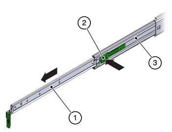
|
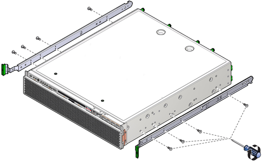
To secure each bracket, use two of the M5 x 12.7 mm screws or two of the M6 x 13 mm screws. Tighten the screws enough to secure the brackets, but leave them loose enough for adjustment later.
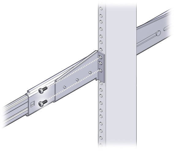
To secure each bracket, use two of the M5 x 12.7 mm screws or two of the M6 x 13 mm screws, as you did in Step 4. Tighten the screws enough to secure the brackets, but leave them loose enough for adjustment later.
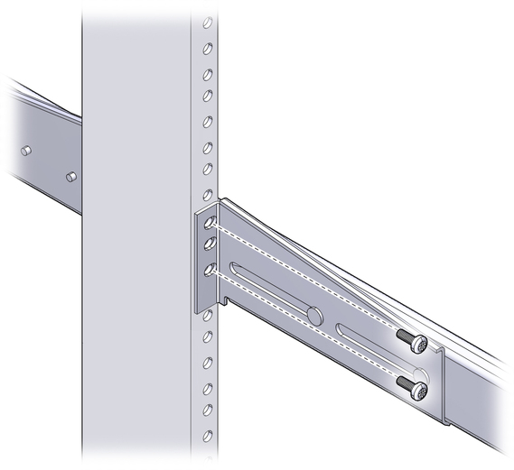
Note - If your rack has 10–32 holes, use the 10–32 collar screws and 10–32 threaded strips.
You might find that there is too much or too little room between the two slides mounted in the rack. Consequently the glides attached to the server might not align correctly with the slides in the rack. If either situation occurs, loosen the screws on the front and back brackets (Step 4 and Step 5), move the brackets inward or outward to the appropriate points, then tighten the brackets again.
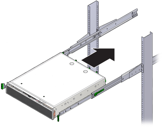
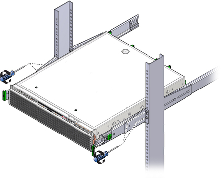
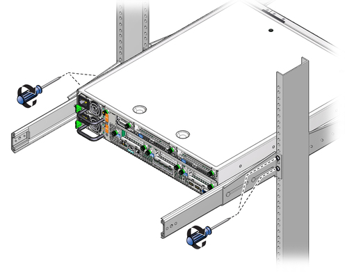
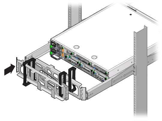
There are labels on both the rails and the CMA. The CMA side that has an arrow attaches to the right inner glide. The other side of the CMA attaches to the outer member.
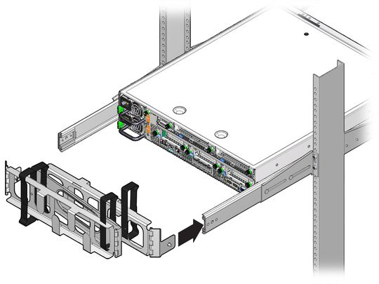
There are labels on both the rails and the CMA. The CMA side that has an arrow attaches to the left inner glide. The other side of the CMA attaches to the outer member.
