| Skip Navigation Links | |
| Exit Print View | |

|
SPARC M5-32 and SPARC M6-32 Servers Administration Guide |
Understanding the System Architecture
Understanding PCIe Device Root Complexes
Control Domain and Reserved Root Complexes
Fully-Populated Default Configuration
Understanding PCIe Slot Root Complex Names and Device Paths
PCIe Device Root Complex Failover Behavior
Understanding EMS SAS Paths to the Internal Drives
SAS Paths From EMS Module to Drives
Understanding Internal Drive Device Paths
HDD and SSD Device Path Differences
Understanding DCU0 Drive Device Paths
Understanding DCU1 Drive Device Paths
Understanding DCU2 Drive Device Paths
Understanding DCU3 Drive Device Paths
Understanding Network Port Device Paths
DCU0 Network Port Device Paths
DCU1 Network Port Device Paths
DCU2 Network Port Device Paths
DCU3 Network Port Device Paths
Understanding Configuration Guidelines
Understanding System Administration Resources
Understanding Platform-Specific Oracle ILOM Features
SPARC: Server-Specific and New Oracle ILOM Features and Requirements
Unsupported Oracle OS Features
Unsupported Oracle ILOM Features
Oracle VM Server for SPARC Overview
Multipathing Software Overview
Oracle ILOM Remote System Console Plus Overview
Oracle Hardware Management Pack Overview
Oracle Enterprise Manager Ops Center
Time Synchronization and NTP Service
Multi-Domain Extensions to ILOM MIBs
Establish a Network Management Connection to Oracle ILOM
Log In to Oracle ILOM (Web Interface)
Logging In to Oracle ILOM (CLI)
Switch Between the Oracle ILOM CLI and the System Console on a Host
Connect to a PDomain When the System Is Unconfigured and Powered Off
Connect to a PDomain When the Oracle Solaris OS Is Running
Connect to a PDomain When the Oracle Solaris OS Is Unresponsive
Get to the ok Prompt When the Host Is Powered On (Web Interface)
Connect to an LDoms Guest Domain
Connect to Oracle ILOM Remote System Console Plus
Enable Video Redirection From the Oracle Solaris OS
Configure Multiple Display Devices
Reestablish KVMS Connection to SPPs After a Reboot
Controlling the Server, Domains, and Devices
Resetting the Server, SP, or Domains
Reset the Server (Oracle Solaris)
Resetting the SP Configuration
Managing the Server's Boot Behavior
Change the Default Boot Device (ok Prompt)
Create an OpenBoot Boot Path to a Boot Disk
Enable or Disable Automatic Booting (ok Prompt)
SPARC: OpenBoot Boot Configuration Parameters
Booting and Shutting Down the OS
Manually Boot the OS (ok Prompt)
Configuring Oracle ILOM User Accounts and Roles
Understanding Platform and Host-Specific User Role Assignments
Configuring User Accounts (SNMP)
Configuring Host Groups to Authenticate User Accounts (CLI)
Configuring Host Groups to Authenticate User Accounts (SNMP)
Record Network Parameter Values
Viewing the Network Configuration
View Configuration Details for the Network
View Configuration Details for SPs and Hosts
Determine Which SP Is the Active SP
Change the Current Role of the SP Pair
Disable or Re-Enable Network Access to an SP or Host
Determine Current DCU Assignment
Migrate DCUs to a New PDomain (CLI)
Administering CMUs, CMPs, and DIMMs
Display Summary of Installed CMUs
Administering IOUs and PCIe Device Root Complexes
Manage I/O Path Reconfiguration Settings
Identify the Root Complex of a Device
Identifying Domain-Level Commands
PDomain Configuration and Monitoring Commands
Single Sign-On Service Network Deployment Commands
Dedicated SP Interconnect Property Commands
FMA Fault Proxying and Reserved Root Complexes
Virtual Keyswitch Property Commands
Locate the Server (Web Interface)
Obtain the Server Serial Number
Viewing Server and Component Information
Viewing System-Level Information
Viewing Individual Component Properties
XSCF and Oracle ILOM Command Comparison
Identifying SP Configuration and Administration Commands
User Account Administration Commands
Network Configuration/Administration Commands
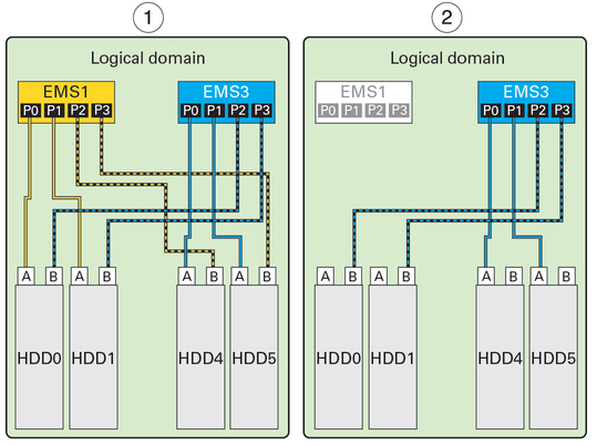
The following illustration shows two examples of a logical domain containing both EMS1 and EMS3. Since both EMS1 and EMS3 provide EMS SAS paths to the same four drives, you can still access all of the drives if one EMS fails (in the second example, EMS1 has failed).

|
When both SAS paths to a drive are within the same logical domain, you can configure them for redundancy using the Oracle Solaris I/O multipathing feature. This feature dynamically controls the paths to storage devices and manages storage path failures. If one SAS path fails, you can configure the multipathing feature to enable the other SAS path to take over.
Note - For complete information about configuring Oracle Solaris I/O multipathing, refer to the Oracle Solaris 11.1 Administration: SAN Configuration and Multipathing document, which is in the Oracle Solaris OS documentation library at http://www.oracle.com/goto/Solaris11/docs.
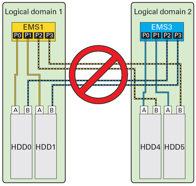
If both SAS paths to the same drive are assigned two different logical domains, make sure that the drive will only be accessed through a single SAS path. When two different logical domains access the same drive simultaneously, the data on the drive becomes corrupted.
For example, if one logical domain contains EMS1 and a second logical domain contains EMS3, both logical domains can access HDD0, HDD1, HDD4, and HDD5 through the two SAS paths to each drive. The same four drives will be displayed in command output in both logical domains.

In this example, configure each logical domain to access the drives through single SAS paths (labeled A). Avoid accessing the other drives through the remaining SAS paths (labeled B).
 | Caution - Never configure the same drive to be a boot device for two or more logical domains. Data corruption will result. |
EMS module-to-drive mapping is as follows.
|