| Skip Navigation Links | |
| Exit Print View | |

|
Oracle Solaris Cluster 4.1 Hardware Administration Manual Oracle Solaris Cluster 4.1 |
| Skip Navigation Links | |
| Exit Print View | |

|
Oracle Solaris Cluster 4.1 Hardware Administration Manual Oracle Solaris Cluster 4.1 |
1. Introduction to Oracle Solaris Cluster Hardware
2. Installing and Configuring the Terminal Concentrator
3. Installing Cluster Interconnect Hardware and Configuring VLANs
4. Maintaining Cluster Interconnect Hardware
5. Installing and Maintaining Public Network Hardware
6. Maintaining Platform Hardware
7. Campus Clustering With Oracle Solaris Cluster Software
Requirements for Designing a Campus Cluster
Selecting Networking Technologies
Complying With Quorum Device Requirements
Replicating Solaris Volume Manager Disksets
Guidelines for Designing a Campus Cluster
Determining the Number of Rooms in Your Cluster
Three-Room Campus Cluster Examples
Deciding How to Use Quorum Devices
Quorum in Clusters With Four Rooms or More
Determining Campus Cluster Connection Technologies
Cluster Interconnect Technologies
Storage Area Network Technologies
Installing and Configuring Interconnect, Storage, and Fibre Channel Hardware
Additional Campus Cluster Configuration Examples
In planning a campus cluster, your goal is to build a cluster that can at least survive the loss of a room and continue to provide services. The concept of a room must shape your planning of redundant connectivity, storage replication, and quorum. Use the following guidelines to assist in managing these design considerations.
The concept of a room, or location, adds a layer of complexity to the task of designing a campus cluster. Think of a room as a functionally independent hardware grouping, such as a node and its attendant storage, or a quorum device that is physically separated from any nodes. Each room is separated from other rooms to increase the likelihood of failover and redundancy in case of accident or failure. The definition of a room therefore depends on the type of failure to safeguard against, as described in the following table.
Table 7-1 Definitions of “Room”
|
Oracle Solaris Cluster does support two-room campus clusters. These clusters are valid and might offer nominal insurance against disasters. However, consider adding a small third room, possibly even a secure closet or vault (with a separate power supply and correct cabling), to contain the quorum device or a third server.
Whenever a two-room campus cluster loses a room, it has only a 50 percent chance of remaining available. If the room with fewest quorum votes is the surviving room, the surviving nodes cannot form a cluster. In this case, your cluster requires manual intervention from your Oracle service provider before it can become available.
The advantage of a three-room or larger cluster is that, if any one of the three rooms is lost, automatic failover can be achieved. Only a correctly configured three-room or larger campus cluster can guarantee system availability if an entire room is lost (assuming no other failures).
A three-room campus cluster configuration supports up to eight nodes. Three rooms enable you to arrange your nodes and quorum device so that your campus cluster can reliably survive the loss of a single room and still provide cluster services. The following example configurations all follow the campus cluster requirements and the design guidelines described in this chapter.
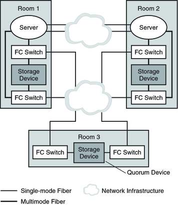
Figure 7-1 shows a three-room, two-node campus cluster. In this arrangement, two rooms each contain a single node and an equal number of disk arrays to mirror shared data. The third room contains at least one disk subsystem, attached to both nodes and configured with a quorum device.
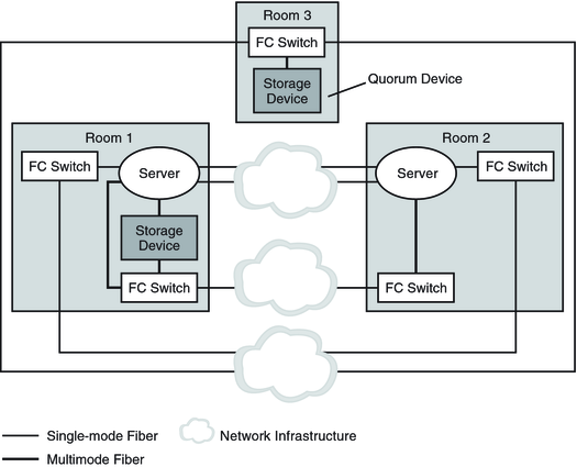
Figure 7-2 shows an alternative three-room, two-node campus cluster.
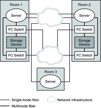
Figure 7-3 shows a three-room, three-node cluster. In this arrangement, two rooms each contain one node and an equal number of disk arrays. The third room contains a small server, which eliminates the need for a storage array to be configured as a quorum device.
Note - These examples illustrate general configurations and are not intended to indicate required or recommended setups. For simplicity, the diagrams and explanations concentrate only on features that are unique to understanding campus clustering. For example, public-network Ethernet connections are not shown.
Figure 7-1 Basic Three-Room, Two-Node Campus Cluster Configuration With Multipathing

In the configuration that is shown in the following figure, if at least two rooms are up and communicating, recovery is automatic. Only three-room or larger configurations can guarantee that the loss of any one room can be handled automatically.
Figure 7-2 Minimum Three-Room, Two-Node Campus Cluster Configuration Without Multipathing

In the configuration shown in the following figure, one room contains one node and shared storage. A second room contains a cluster node only. The third room contains shared storage only. A LUN or disk of the storage device in the third room is configured as a quorum device.
This configuration provides the reliability of a three-room cluster with minimum hardware requirements. This campus cluster can survive the loss of any single room without requiring manual intervention.
Figure 7-3 Three-Room, Three-Node Campus Cluster Configuration

In the configuration that is shown in the preceding figure, a server acts as the quorum vote in the third room. This server does not necessarily support data services. Instead, it replaces a storage device as the quorum device.
When adding quorum devices to your campus cluster, your goal should be to balance the number of quorum votes in each room. No single room should have a much larger number of votes than the other rooms because loss of that room can bring the entire cluster down.
For campus clusters with more than three rooms and three nodes, quorum devices are optional. Whether you use quorum devices in such a cluster, and where you place them, depends on your assessment of the following:
Your particular cluster topology
The specific characteristics of the rooms involved
Resiliency requirements for your cluster
As with two-room clusters, locate the quorum device in a room you determine is more likely to survive any failure scenario. Alternatively, you can locate the quorum device in a room that you want to form a cluster, in the event of a failure. Use your understanding of your particular cluster requirements to balance these two criteria.
Refer to the Oracle Solaris Cluster Concepts Guide for general information about quorum devices and how they affect clusters that experience failures. If you decide to use one or more quorum devices, consider the following recommended approach:
For each room, total the quorum votes (nodes) for that room.
Define a quorum device in the room that contains the lowest number of votes and that contains a fully connected shared storage device.
When your campus cluster contains more than two nodes, do not define a quorum device if each room contains the same number of nodes.
The following sections discuss quorum devices in various sizes of campus clusters.
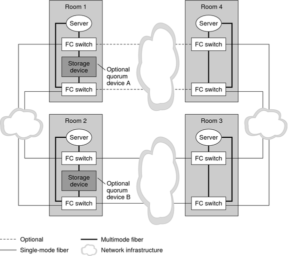
The following figure illustrates a four-node campus cluster with fully connected storage. Each node is in a separate room. Two rooms also contain the shared storage devices, with data mirrored between them.
Note that the quorum devices are marked optional in the illustration. This cluster does not require a quorum device. With no quorum devices, the cluster can still survive the loss of any single room.
Consider the effect of adding Quorum Device A. Because the cluster contains four nodes, each with a single quorum vote, the quorum device receives three votes. Four votes (one node and the quorum device, or all four nodes) are required to form the cluster. This configuration is not optimal, because the loss of Room 1 brings down the cluster. The cluster is not available after the loss of that single room.
If you then add Quorum Device B, both Room 1 and Room 2 have four votes. Six votes are required to form the cluster. This configuration is clearly better, as the cluster can survive the random loss of any single room.
Figure 7-4 Four-Room, Four-Node Campus Cluster

Consider the optional I/O connection between Room 1 and Room 4. Although fully connected storage is preferable for reasons of redundancy and reliability, fully redundant connections might not always be possible in campus clusters. Geography might not accommodate a particular connection, or the project's budget might not cover the additional fiber.
In such a case, you can design a campus cluster with indirect access between some nodes and the storage. In Figure 7-4, if the optional I/O connection is omitted, Node 4 must access the storage indirectly.
In three-room, two-node campus clusters, you should use the third room for the quorum device (Figure 7-1) or a server (Figure 7-3). Isolating the quorum device gives your cluster a better chance to maintain availability after the loss of one room. If at least one node and the quorum device remain operational, the cluster can continue to operate.
In two-room configurations, the quorum device occupies the same room as one or more nodes. Place the quorum device in the room that is more likely to survive a failure scenario if all cluster transport and disk connectivity are lost between rooms. If only cluster transport is lost, the node that shares a room with the quorum device is not necessarily the node that reserves the quorum device first. For more information about quorum and quorum devices, see the Oracle Solaris Cluster Concepts Guide.