| Skip Navigation Links | |
| Exit Print View | |

|
Sun Blade X4-2B Service Manual |
Troubleshooting the Server Module
Preparing the Server Module for Component Replacement
Powering Down the Server Module
About Server Power States and Resets
Power Off, Graceful (Power Button)
Power Off, Immediate (Power Button)
Power Off, Remote (Oracle ILOM CLI)
Power Off, Remote (Oracle ILOM Web Interface)
Performing ESD and Anti-static Prevention Measures
Use an Anti-static Wrist Strap and an Anti-static Mat
Server Module and Component Filler Panels
Install Server Module Filler Panels
Remove the Server Module Top Cover
Turning the Locate Indicator On and Off
Turn On the Locate Indicator Remotely (Oracle ILOM CLI)
Turn On the Locate Indicator Remotely (Oracle ILOM Web Interface)
Turn the Locate Indicator On and Off Locally
Servicing Server Module Components
Returning the Server Module to Operation
BIOS Power-On Self-Test (POST) Checkpoints
To service internal server components and to troubleshoot processors and DIMMs using the motherboard Fault Remind circuitry, you need to remove the server module from the chassis. Removing the server module leaves a vacant slot in the chassis, which disrupts the chassis cooling and airflow system. The system requires that every chassis slot contain a component, either a server module, a storage module, or a server module filler panel.
Before You Begin
See Preparing for Service .
You need a replacement server module, a storage module, or a server module filler panel, to fill the vacant slot created when you remove the server module. For more information, see Install Server Module Filler Panels.
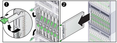
The result of this action disengages the server module, places it in a no-power state, and leaves it protruding approximately three inches from the front of the chassis.
Caution - Component damage or personal injury. Blades can weigh up to 22 lbs (10kg). Use two hands to install or remove the blade from the chassis. Do not attempt to remove the server module from the chassis using the ejector levers. |

Rotate the handles inward toward the server module front panel until they lock (click) into place.
Next Steps