| Skip Navigation Links | |
| Exit Print View | |

|
Sun Ethernet Fabric Operating System PIMv6 Administration Guide |
| Skip Navigation Links | |
| Exit Print View | |

|
Sun Ethernet Fabric Operating System PIMv6 Administration Guide |
Configuring the Topology Example
Enable IPv6 Support and Assign IPv6 Addresses
Configure the Group and Source Thresholds
Configure the SPT Switching Period
Configure the Rendezvous Point Threshold
Configure the RP Switch Period
Configure the regstop Rate Limit
Configuring PIMv6 on an Interface
Associate the PIMv6 Component to an Interface
Configure the Query-Interval Value
Configure the DR Priority Value
Configure the Override Interval
Configure the Message Interval
Configuring the PIMv6 Component
Set the Mode for the PIMv6 Component
Configure the RP-Candidate Hold Time
Configure the RP-Candidate Address
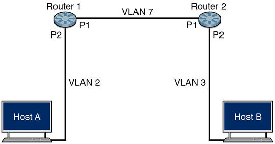
Before enabling PIMv6 in a router, you must configure the router and the host with the IP address and VLAN connectivity. The following example topology is referenced in the configuration steps in this guide.

This topology consists of two routers (router A and router B) with two physical interfaces (P1 and P2), which are extreme-ethernet 0/1 and extreme-ethernet 0/2 respectively.
The following table shows the configuration values of the IPv4 and IPv6 addresses for each interface.
|