| Skip Navigation Links | |
| Exit Print View | |

|
Oracle SuperCluster M6-32 Owner's Guide: Overview |
Determining SuperCluster M6-32 Configurations
Determine the Number of Compute Servers
Determine the Number of DCUs in Each Compute Server
Determine the Number of CMUs in Each DCU
Determine the Amount of Memory in Each DCU
Determine the PDomain Configuration on Each Compute Server
Determine the LDom Configuration for Each PDomain
Determining the Best Configuration for Your Situation
Understanding PDomain Configurations
Type of Configuration PDomains
Allocating CPU Resources for LDoms
CPU Resources for LDoms Flowchart
Compute Server Level Considerations
Allocating Memory Resources for LDoms
Memory Resources for LDoms Flowchart
Compute Server Level Considerations
Understanding PCIe Cards and Slots for LDoms
PCIe Cards and Slots for LDoms Flowchart
Compute Server Level Considerations
Understanding Storage for LDoms
Compute Server Level Considerations
Understanding SuperCluster M6-32
Identifying SuperCluster M6-32 Components
Understanding the Compute Server
Understanding DCU Configurations
PCIe Device Root Complexes Overview
PCIe Communication and Paths Overview
Understanding DCU PCIe and EMS Slot Locations
Understanding Half-Populated DCU Root Complexes
Half-Populated DCU 0 PCIe Slot Root Complexes
Half-Populated DCU 1 PCIe Slot Root Complexes
Half-Populated DCU 2 PCIe Slot Root Complexes
Half-Populated DCU 3 PCIe Slot Root Complexes
Understanding Fully-Populated DCU Root Complexes
Fully-Populated DCU 0 PCIe Slot Root Complexes
Fully-Populated DCU 1 PCIe Slot Root Complexes
Fully-Populated DCU 2 PCIe Slot Root Complexes
Fully-Populated DCU 3 PCIe Slot Root Complexes
Extended Configuration PDomain Overview
Understanding Extended Configuration PDomains
Understanding Four DCUs in One Compute Server (R1 Extended Configuration PDomains)
Understanding Four DCUs Across Two Compute Servers (R2 Extended Configuration PDomains)
Understanding Base Configuration PDomains
Understanding Four DCUs on One Compute Server (R3 Base Configuration PDomains)
Understanding Four DCUs Across Two Compute Servers (R4 Base Configuration PDomains)
Understanding Two DCUs on One Compute Server (R5 Base Configuration PDomains)
Understanding Two DCUs Across Two Compute Servers (R6 Base Configuration PDomains)
Understanding Compute Server Hardware and Networks
CPU and Memory Resources Overview
LDoms and the PCIe Slots Overview
10GbE Client Access Network Overview
Understanding SR-IOV Domain Types
Understanding LDom Configurations for Extended Configuration PDomains
Understanding LDom Configurations for Fully-Populated DCUs (Extended Configuration PDomains)
Understanding LDom Configurations for Half-Populated DCUs (Extended Configuration PDomains)
Understanding LDom Configurations for Base Configuration PDomains
Understanding LDom Configurations for Fully-Populated DCUs (Base Configuration PDomains)
Understanding LDom Configurations for Half-Populated DCUs (Base Configuration PDomains)
Understanding Clustering Software
Cluster Software for the Database Domain
Cluster Software for the Oracle Solaris Application Domains
Understanding System Administration Resources
Understanding Platform-Specific Oracle ILOM Features
SPARC: Server-Specific and New Oracle ILOM Features and Requirements
Unsupported Oracle ILOM Features
Oracle ILOM Remote Console Plus Overview
Oracle Hardware Management Pack Overview
Time Synchronization and NTP Service
A Root Domain is an SR-IOV domain that hosts the physical I/O devices, or physical functions (PFs), such as the IB HCAs, EMSs, and any Fibre Channel cards installed in the PCIe slots. Almost all of its CPU and memory resources are parked for later use by I/O Domains. Logical devices, or virtual functions (VFs), are created from each PF, with each PF hosting 32 VFs.
Because Root Domains host the physical I/O devices, just as dedicated domains currently do, Root Domains essentially exist at the same level as dedicated domains.
With the introduction of Root Domains, the following parts of the domain configuration for SuperCluster M6-32 are set at the time of the initial installation and can only be changed by an Oracle representative:
Type of domain:
Root Domain
Application Domain running Oracle Solaris 10 (dedicated domain)
Application Domain running Oracle Solaris 11 (dedicated domain)
Database Domain (dedicated domain)
Number of Root Domains and dedicated domains on the server
A domain can only be a Root Domain if it has either one or two IB HCAs associated with it. A domain cannot be a Root Domain if it has more than two IB HCAs associated with it. If you have a domain that has more than two IB HCAs associated with it (for example, the B4-1 domain), then that domain must be a dedicated domain.
When deciding which domains will be a Root Domain, the last domain must always be the first Root Domain, and you would start from the last domain in your configuration and go in for every additional Root Domain. For example, assume you have four domains in your configuration, and you want two Root Domains and two dedicated domains. In this case, the first two domains would be dedicated domains and the last two domains would be Root Domains.
Note - Even though a domain with two IB HCAs is valid for a Root Domain, domains with only one IB HCA should be used as Root Domains. When a Root Domain has a single IB HCA, fewer I/O Domains have dependencies on the I/O devices provided by that Root Domain. Flexibility around high availability also increases with Root Domains with one IB HCA.
The following domains have only one or two IB HCAs associated with them and can therefore be used as a Root Domain:
Fully-populated DCUs (either base or extended configurations):
- Domains associated with two CMPs (one IB HCA)
- Domains associated with four CMPs (two IB HCAs)
Half-populated DCUs (either base or extended configurations):
- Domains associated with one CMP (one IB HCA)
- Domains associated with two CMPs (two IB HCAs)
In addition, the first domain in the system (the Control Domain) will always be a dedicated domain. The Control Domain cannotbe a Root Domain. Therefore, you cannot have all of the domains on your server as Root Domains, but you can have a mixture of Root Domains and dedicated domains on your server or all of the domains as dedicated domains.
A certain amount of CPU core and memory is always reserved for each Root Domain, depending on which domain is being used as a Root Domain in the domain configuration and the number of IB HCAs that are associated with that Root Domain:
The last domain in a domain configuration:
Two cores and 32 GB of memory reserved for a Root Domain with one IB HCA
Four cores and 64 GB of memory reserved for a Root Domain with two IB HCAs
Any other domain in a domain configuration:
One core and 16 GB of memory reserved for a Root Domain with one IB HCA
Two cores and 32 GB of memory reserved for a Root Domain with two IB HCAs
Note - The amount of CPU core and memory reserved for Root Domains is sufficient to support only the PFs in each Root Domain. There is insufficient CPU core or memory resources to support zones or applications in Root Domains, so zones and applications are supported only in the I/O Domains.
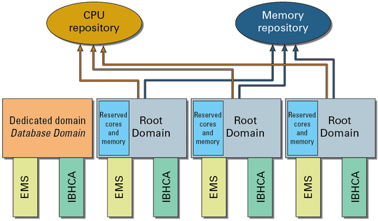
The remaining CPU core and memory resources associated with each Root Domain are parked in CPU and memory repositories, as shown in the following graphic.

CPU and memory repositories contain resources not only from the Root Domains, but also any parked resources from the dedicated domains. Whether CPU core and memory resources originated from dedicated domains or from Root Domains, once those resources have been parked in the CPU and memory repositories, those resources are no longer associated with their originating domain. These resources become equally available to I/O Domains.
In addition, CPU and memory repositories contain parked resources only from the PDomain that contains the domains providing those parked resources. In other words, if you have two PDomains and both PDomains have Root Domains, there would be two sets of CPU and memory repositories, where each PDomain would have its own CPU and memory repositories with parked resources.
For example, assume you have the B2-4 LDom configuration, with four domains on your PDomain, with three of the four domains as Root Domains, as shown in the previous graphic. Assume each domain has the following IB HCAs and EMSs, and the following CPU core and memory resources:
One IB HCA and one EMS
12 cores
512 GB of memory (16GB DIMMs)
In this situation, the following CPU core and memory resources are reserved for each Root Domain, with the remaining resources available for the CPU and memory repositories:
Two cores and 32 GB of memory reserved for the last Root Domains in this configuration. 10 cores and 480 GB of memory available from this Root Domain for the CPU and memory repositories.
One core and 16 GB of memory reserved for the second and third Root Domains in this configuration.
11 cores and 496 GB of memory available from each of these Root Domains for the CPU and memory repositories.
A total of 22 cores (11 x 2) and 992 GB of memory (496 GB x 2) available for the CPU and memory repositories from these two Root Domains.
A total of 32 cores (10 + 22 cores) are therefore parked in the CPU repository, and 1472 GB of memory (480 + 992 GB of memory) are parked in the memory repository and are available for the I/O Domains.
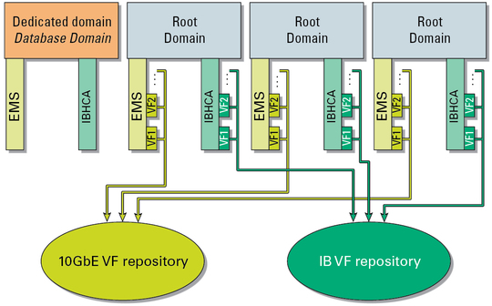
With Root Domains, connections to the 10GbE client access network go through the physical ports on each EMS, and connections to the IB network go through the physical ports on each IB HCA, just as they did with dedicated domains. However, cards used with Root Domains must also be SR-IOV compliant. SR-IOV compliant cards enable VFs to be created on each card, where the virtualization occurs in the card itself.
The VFs from each Root Domain are parked in the IB VF and 10GbE VF repositories, similar to the CPU and memory repositories, as shown in the following graphic.

Even though the VFs from each Root Domain are parked in the VF repositories, the VFs are created on each EMS and IB HCA, so those VFs are associated with the Root Domain that contains those specific EMSs and IB HCA cards. For example, looking at the example configuration in the previous graphic, the VFs created on the last (rightmost) EMS and IB HCA will be associated with the last Root Domain.